Leaderboard
-
mikeymad
High Rollers6Points13709Posts -
morphsci
High Rollers6Points13301Posts -
blessingx
High Rollers5Points17613Posts -
MexicanDragon
High Rollers3Points8364Posts


Popular Content
Showing content with the highest reputation on 06/02/23 in all areas
-
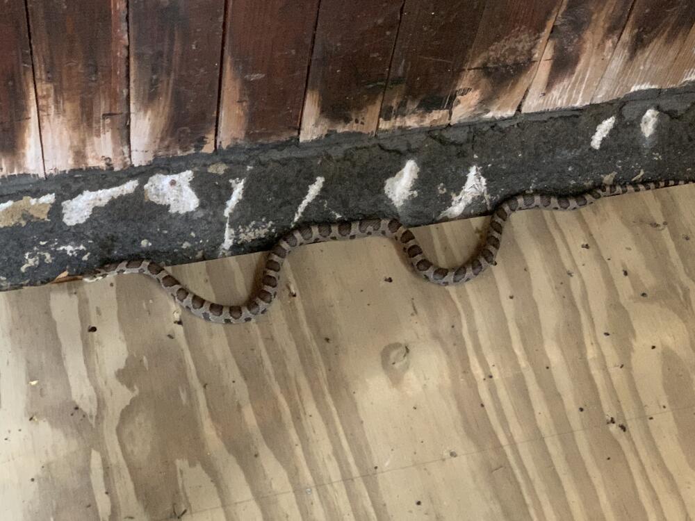
3 pointsWas straightening up our upstairs garage and I came across this trespasser trying to be inconspicuous
 3 points
 -
3 points
-
2 points
-
Some British guys blowing up small electrolytic capacitors by putting too much voltage on them, in slow motion. Like they said "don't try this at home"2 points
-
Cry Softly Lonely One (Remastered) Roy Orbison 1967 https://album.link/i/1443310520 Example: You may not know them all - but they are worthy.2 points
-
2 pointsGrahame! Al! Everybody! I miss you guys! Amazing to see everyone on here...2 points
-
1 pointThe offset of the output stage is maintained by the Q33-Q32 servo and they'll fight against any adjustment you make on the active batteries in the attempt to bring down the offset. My preferred solution (which may not be popular here) is to change R73 (6.2k) to a 10k multi-turn trimmer so that offset and balance adjustments can be de-coupled. In terms of balance, the balance servo around the LF353 has a relatively narrow compliance range. If you did not pay great attentions to the parts matching between the +/- arms of a channel, especially the triode-to-triode matching in the 6DJ8 tubes, chances are the LF353 opamps could bottom out trying to balance. Check the output voltage of the U7 and U8 opamps. The difference between them tells us how unmatched the two arms are. If any of them gets close to the rail (>10V or <-9V) I'd want to intervene. Adjusting the two active batteries' voltages in the same channel in opposite directions can bring the balance servo back to their comfort zone. Swapping the 6DJ8 tubes may also help, if one has better matched triodes than the other. Mismatching is not always a bad thing - slight mismatch adds some 2nd order harmonic which is pleasing to the ear. 740V on the active battery is a starting point/nominal, you may end up a couple of volts away from the nominal which would be fine.1 point
-
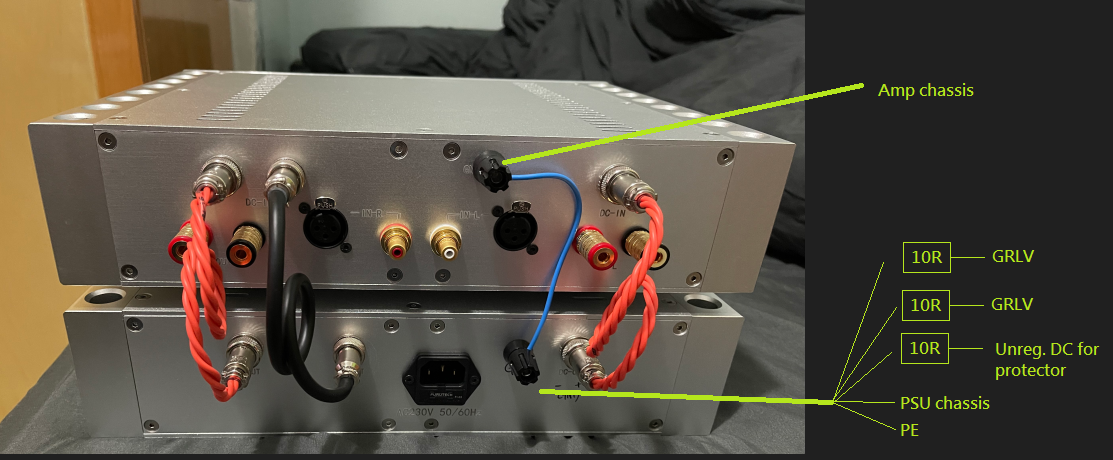
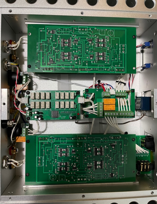
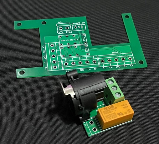
Thanks audiostar for crucial knowledge about grounding. Added banana jacks to both Amp & PSU chassis for grounding. When all cables are connected, circuit ground is measured ~3.5ohms to PE and every parts of the two chassis are 0ohm to PE. Next step is shielding the two DC cables to block out noise. Also made some PCBs for simplify wiring, reduce half of the cables. On the RCA/XLR board, XLR (1) & RCA GND connect to chassis through mounting screw of NC3FAAH2. Relay NC for HOT&COLD, NO for RCA (+) and short (-) to circuit ground. The larger board is used for switching headphone/speaker output. R- & L- are bypassed, only switching R+ & L+ between two outputs. Similar to Kevin's protector, cutoff R+ & L+ when DC occur. With those hollow areas, I can access the underneath protector much easier. Input transistors swapped to J109/K389 with 50K attenuator. Bias set to 150mv and temperature raises from 20°C to 45°C. Although this temp is ok for transistors but don't want being to hot as a desktop setup.

 1 point
 -
1 point
-
1 point
-
Schubert: Symphonies Nos. 3 In D, D.200 & 8 In B Minor, D.759 - "Unfinished" Wiener Philharmoniker, Carlos Kleiber 1997 https://album.link/i/1585387022 Example: All around a super solid performance and recording by DG. Engaging, pretty and good pace. Very much enjoyed my time with this one.1 point
-
1 point
-
1 point
-
1 pointHi Spritzer - I'm in the market for a good mixing can - I've used all the usual suspects. I mainly use my ATC SCM150asl speakers, but I haven't been able to dig on any cans in a while for mixing / mastering duties. It's gotten so bad I mainly check my mixes on Etymotic ER4S if I am going to listen to headphones at all.. times have changed. Should I give those L500Mk2's a shot? Oh and pardon the thread revival. This is my first post in... years.... Best, Neil1 point
-
From recall, it seemed that the Dynahi was more clinical than the CFA3. Not that the CFA3 lacks detail at all, I guess your description of rude might be a good way of putting it. They are both great amps, I just prefer the CFA.1 point