Leaderboard
-
mikeymad
High Rollers4Points13709Posts -
Grahame
High Rollers4Points16720Posts -
morphsci
High Rollers4Points13301Posts -
Dusty Chalk
Moderators3Points49019Posts


Popular Content
Showing content with the highest reputation on 06/03/23 in all areas
-
3 points
-
3 points
-
Making good output transformers for tubes and not even estats have a pi chart of choices to make 1. Good Frequency response & low distortion 2. Cheap 3. Small You can only pick 2. Using a cheaper core than absolute ultimate ends in tears. Even if your core is very big but cheap the frequency response is still bad. And even in most cases, you can't have expensive and small, just doesn't exist And even the best core isn't a surefire way to make a good output transformer, winding method being also one of them If you think all that metal somehow is faster than just raw amplification then you know nothing about transformers1 point
-
1 pointI had a lot of snakes and lizards growing up but my favorite was a beautiful California King Snake whose favorite activity was me carrying her around draped across my shoulders. She was very content to just chill there for hours.1 point
-
1 point
-
Hmm, while XLR pin 1 is fine going to chassis as it is basically shield, RCA GND should not go to chassis. This is why the RCA sockets have an insulation ring. It goes to circuit ground and is shorted to - half of the channel when the RCA input is engaged. This is a balanced amp, so I would switch all 4 channels (+ and - halves) between the outputs. And I would handle the speakers like balanced headphones, i.e. wire the +/- to the banana plugs and not circuit ground. Especially important when using a balanced source. For when you use the RCA input, the - half would be shorted to circuit ground anyway.1 point
-
1 point
-
1 pointWas straightening up our upstairs garage and I came across this trespasser trying to be inconspicuous
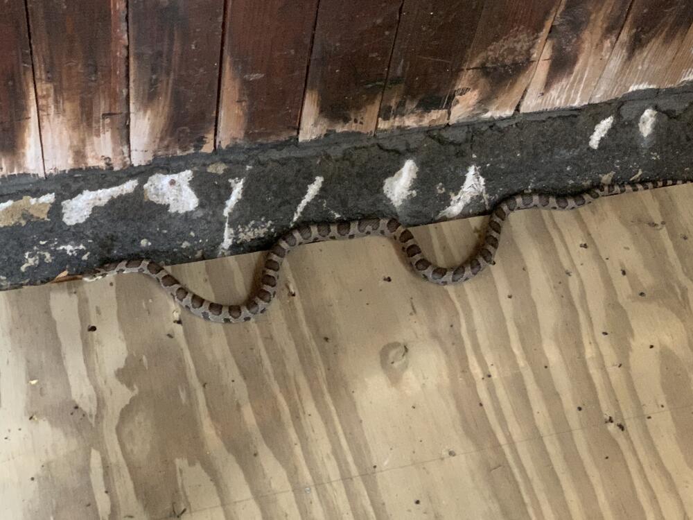 1 point
 -
1 pointWAY, WAY behind… https://www.instagram.com/reel/CshrCHuvxZd/?igshid=MmJiY2I4NDBkZg==1 point
-
Some British guys blowing up small electrolytic capacitors by putting too much voltage on them, in slow motion. Like they said "don't try this at home"1 point
-
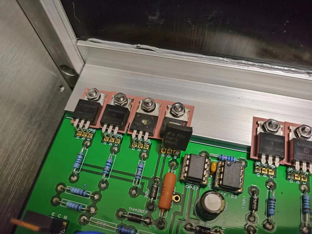
1 pointFinally found the cause of the explosion.The cutouts in the radiator are slightly crooked, and despite the fact that I used insulation pads and insulation gaskets, they unbelievably caused a short circuit. Silicone pads have no problem with their insulating properties, but they are too thin and can create physical contact in some extreme cases. I have replaced them with ceramic insulation pads and what are indeed much safer. This is an important lesson for me. However, it is good to find the cause of the problem.1 point
-
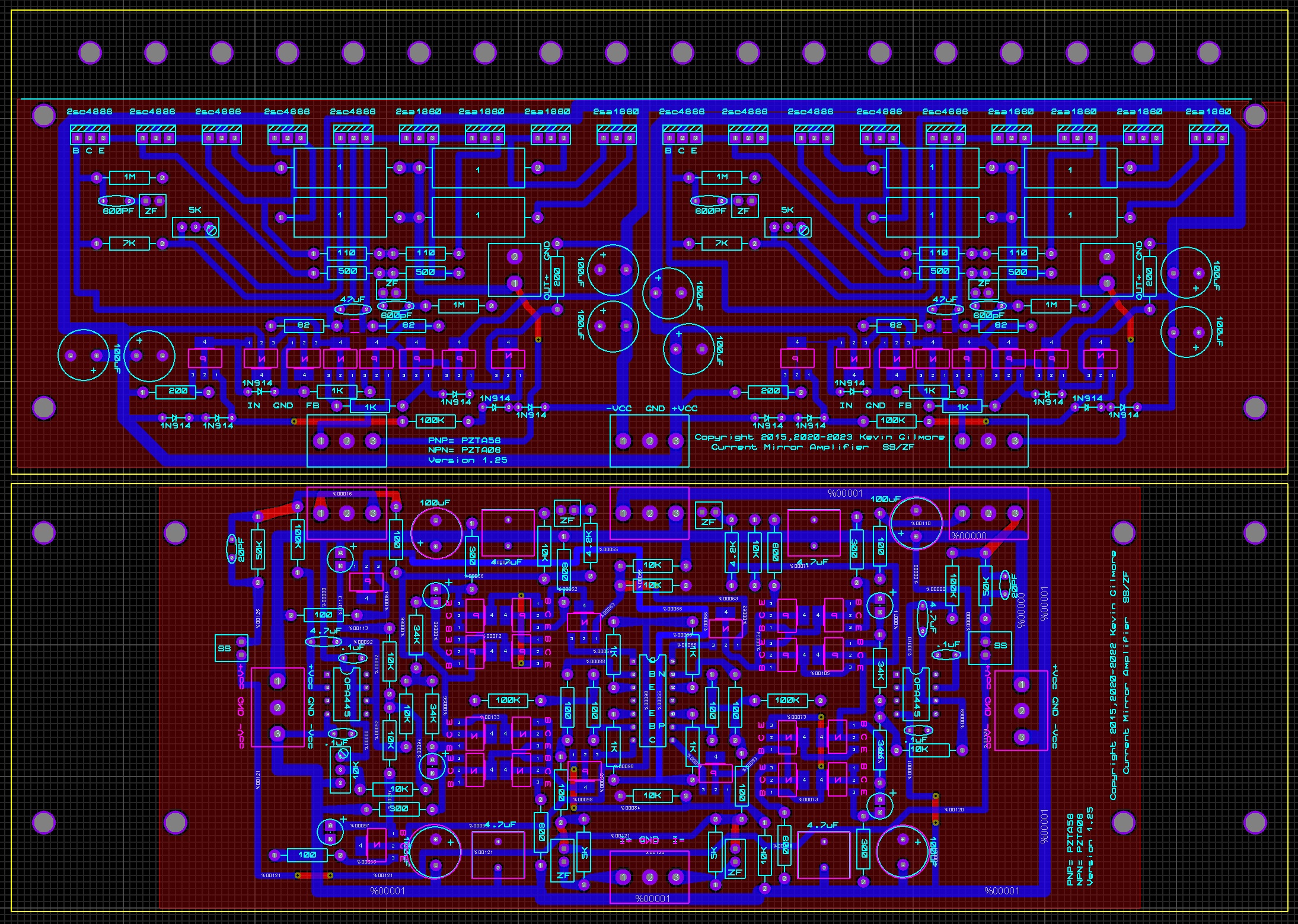
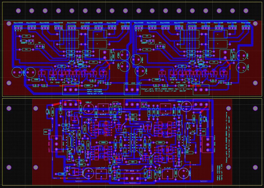
a pre turkey day new year teaser. sanken output transistors, in parallel. with appropriate switching power supplies, capable of about 25 amperes. can be built with 30v, 35v, 40v power supplies if you change out the pzta06/pzta56 with bf722/bf723 then you can go up to 60v supplies. with 40v supplies and big enough heatsinks, 100 watts rms into 8 ohms. lets see how much joamat can shrink this one. balanced output impedance, .5 ohm
 1 point
 -
0 points
-
0 pointsHi guys, I spent 2 months building a T2 and today was expected to be the day of completion, but it exploded. When the power supply is not loaded, everything is fine and the correct voltage can be output. However, I connected the amplifier and turned on the power, and after 6 seconds of high voltage start-up, the power supply exploded. 10M90S I get it from MOUSER, it should not be a fake. I set both RV1 and RV2 in the center. The explosion killed the 10M90S,fqp8n80c,1N4007 and 1n4751a at +500V, and the same situation over at -500V. Did I do something wrong?Why did it explode?Expect someone to answer,THX
 0 points