luvdunhill
-
Posts
13,727 -
Joined
-
Last visited
-
Days Won
40
Content Type
Profiles
Forums
Events
Everything posted by luvdunhill
-
Assemblage 2.6/2.7 and Icarium rants
luvdunhill replied to dreamwhisper's topic in Home Source Components
-
looky here... [ATTACH=CONFIG]3305[/ATTACH]

-
Is that guy wearing a toga?
-
So far (1 season of LOM and 2 seasons of A2A) I'd say Ashes to Ashes is the better series. US version? Forgetaboutit... Sorta dragged into Luther at the moment though...
-
ok, I see the 75VAC winding goes through the TL783 then is reference to the -500VDC winding to make -560VDC. Check. Then that same -560VDC is added to one of the 285 VAC windings to make -260 VDC (so 300VDC) supply and the other 285 VAC winding is used to make to make a 250 VDC supply? Ok..
-
Good point Craig. I realized the two 6.3/4A windings and mentioned these, but didn't realize any of the HT transformer windings qualified. Which would those be again? I was told that adjacent windings without extra insulation can hold off 500VAC, so I suppose I need to know which of the others that this isn't sufficient need the extra insulation.
-
given the board footprint for the power transformer, the only way you could have a transformer that could be put in backwards, is if you were missing two pins, specifically the key and the one diagonally across from it... unless I'm missing something.
-
Um yeah? Yeah, I wasn't thinking... Powder coating better than anodizing, really? I didn't know that one...
-
nah, silver dissipates heat better (i.e. raw aluminum)
-
you'd have to be pretty damn determined to do that
-
.. and one more thing. Is there a preferable relationship to the primary entry point and the secondary exit point on the toroid? 180 degrees? 45 degrees?
-
did you test the transformers with a load as well (rated maximum load or actual load?) Also, thanks for the transformer specs. Could you also give us the maximum gauge that each lead can be (so, pad diameter) and the maximum lead length we need?
-
0.o
-
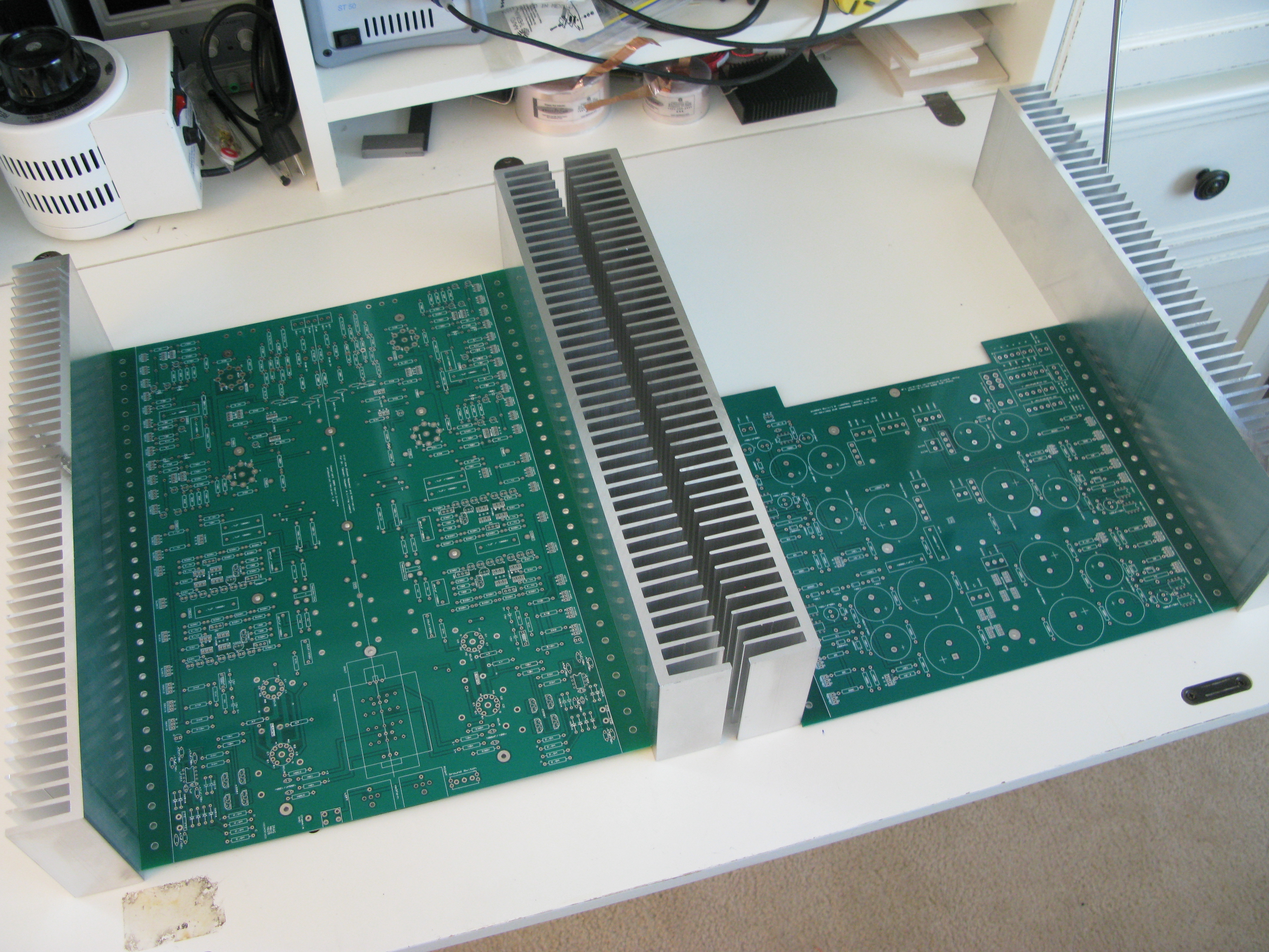
four pair of these:
-
check Doug's post above, it should help you out.
-
Woah Al. What's the occasion?
-
well-done kind sir!
-
perhaps traditional dynamic drivers would have been better. You looked at the right page though, the explanation is right about the paragraph you excised: "It is a power trans-conductance amplifier (or power current source, if you like), replicating an input voltage into an output current. A regular amplifier sends output voltage to the loudspeaker. This is not that kind of amplifier. This amplifier ignores the elements in series with the load circuit, including back-emf, wire resistance, inductance and such, and creates voice coil acceleration in direct proportion to the input signal." Has anyone here heard (or considered the upgrades) the F1J?
-
MoAT MoAT MoAT MoAT MoAT ?
-
Perhaps I missed the proper "turn on" then?
-
elnero: when you turn your head to the extreme left or right (keeping your body facing forward) does the seal stay or can you hear it loosen up?
-
hm.. did I mention the legs? oh, regarding the different direction, I feel that knife switches are under-appreciated:
-
.. it's a red double D though.. does that help?
-
Member of Another Trade?
-
Tom, what I meant was, installing the heat sink and then tapping the two holes in the top of heat sink and then screw the lid down into these holes. Thus using the the heat sink itself as a heat transfer mechanism to the case. I cannot find any pics of me doing this, but I've done it quite a bit with good results. However, point taken about the case already getting pretty warm.