

Leaderboard
-
Voltron
High Rollers25Points34514Posts -
acidbasement
High Rollers8Points2987Posts -
Laowei
Returning Member7Points597Posts -
shellylh
High Rollers7Points18862Posts


Popular Content
Showing content with the highest reputation on 02/14/19 in all areas
-
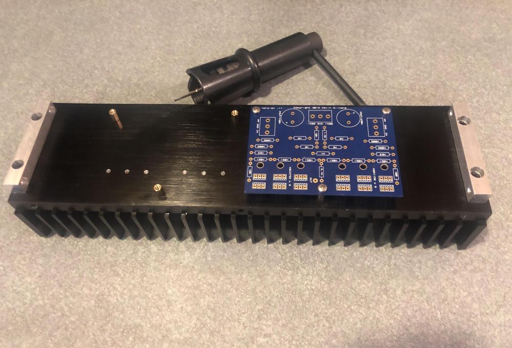
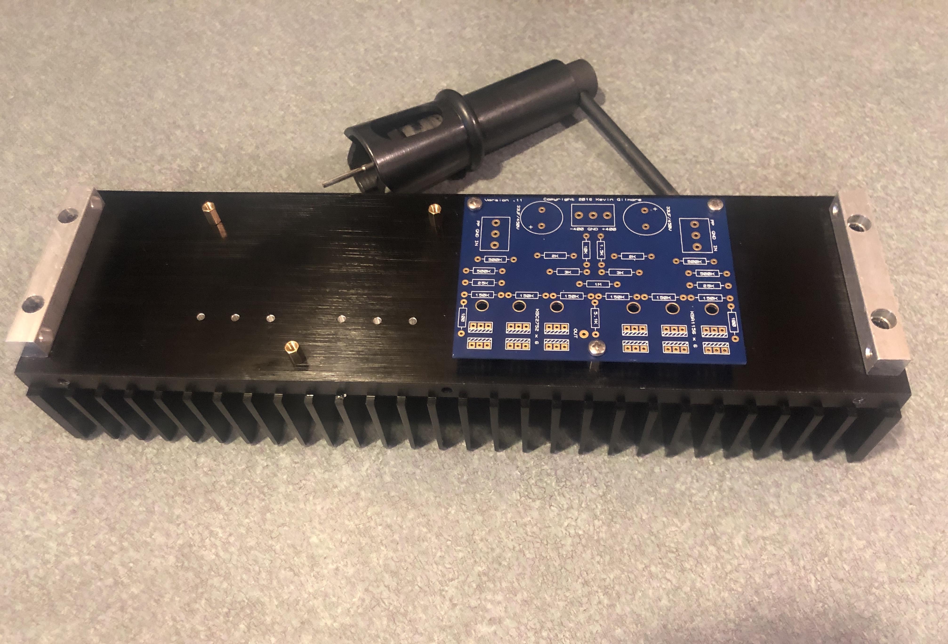
6 pointsRecieved my Shars Tap Holder this afternoon. Put it to use on a CF electrostatic amp I have been putting off working on because I dreaded tapping threaded holes by hand. It really works slick and the results came out great. Thanks for posting this Kerry. Nothing beats the right tool for the job.
 6 points
 -
2 pointsListening over and over and over again...2 points2 pointsSilver had to go to the vet, today, for an upper respiratory infcection. You would have thought she was being murdered. Now she is very sleepy.
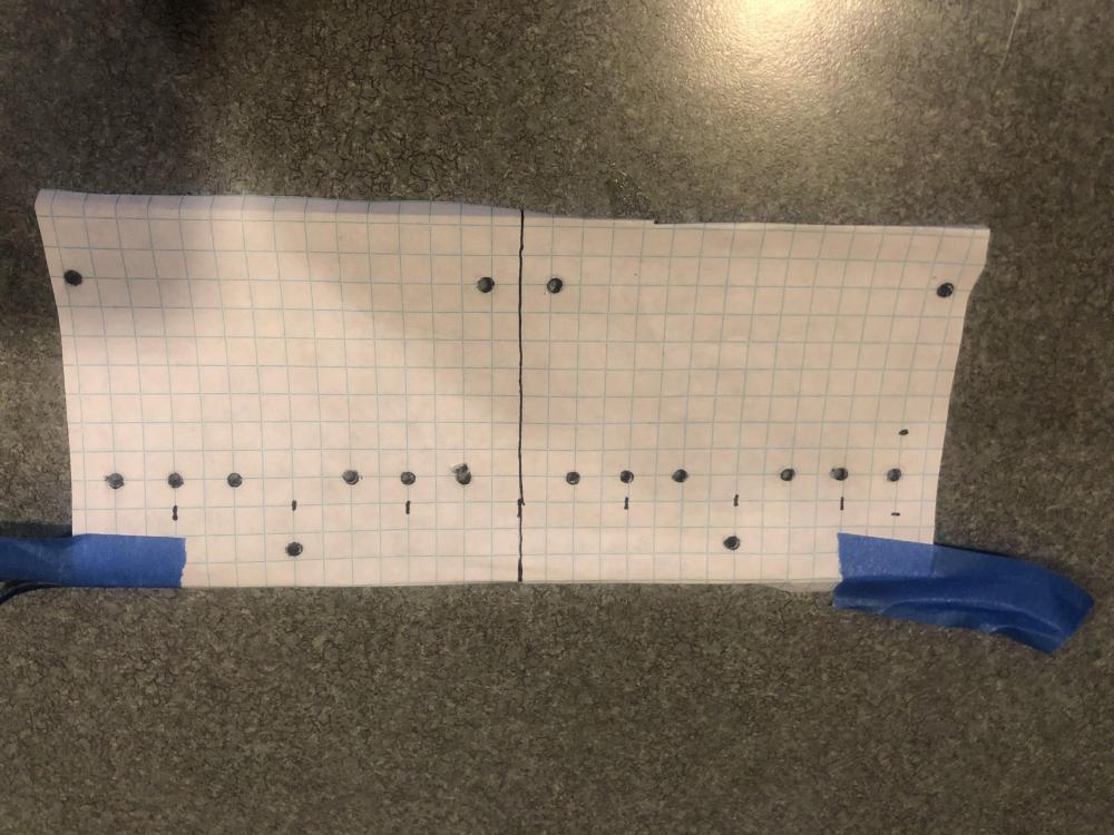
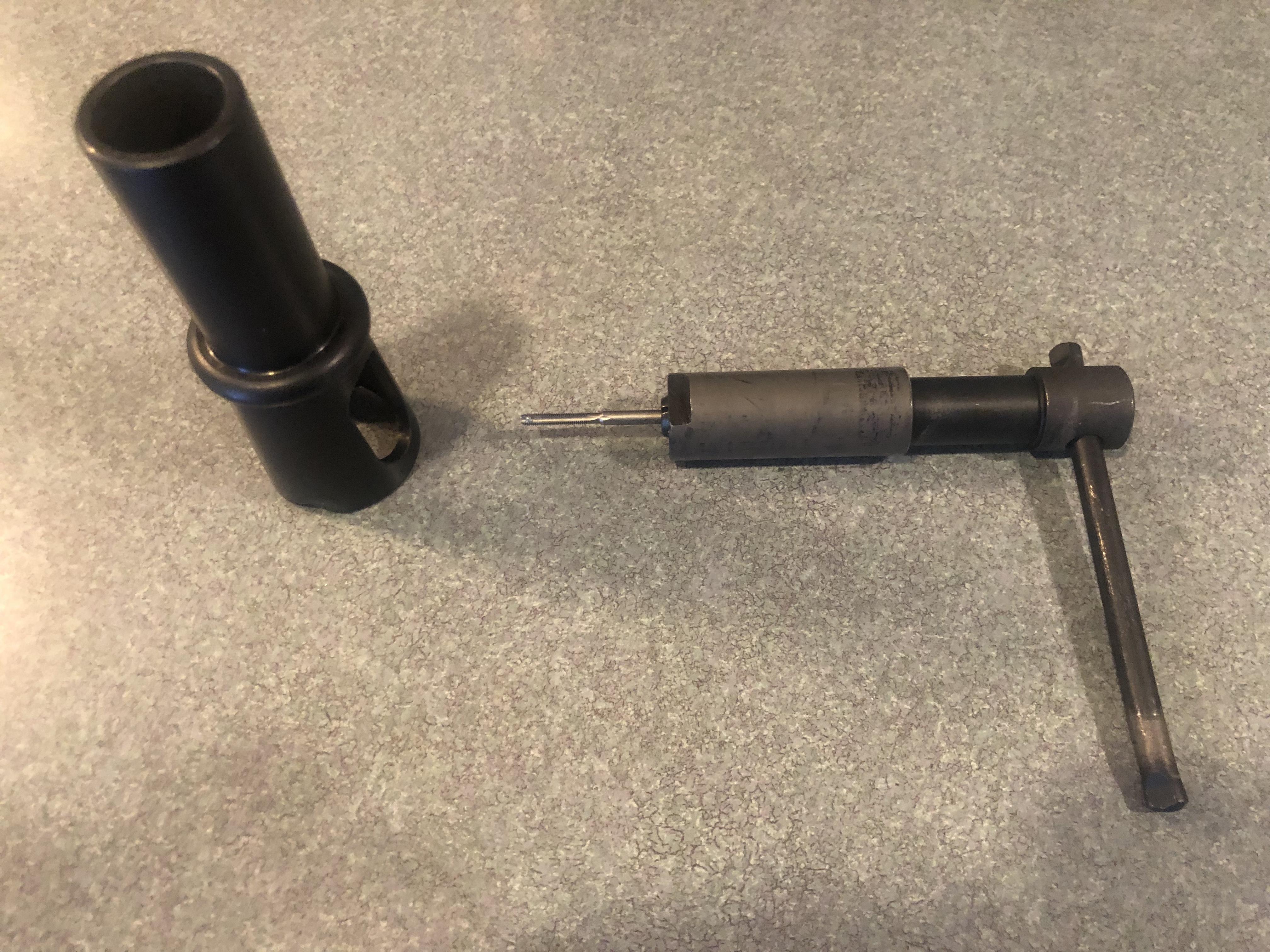
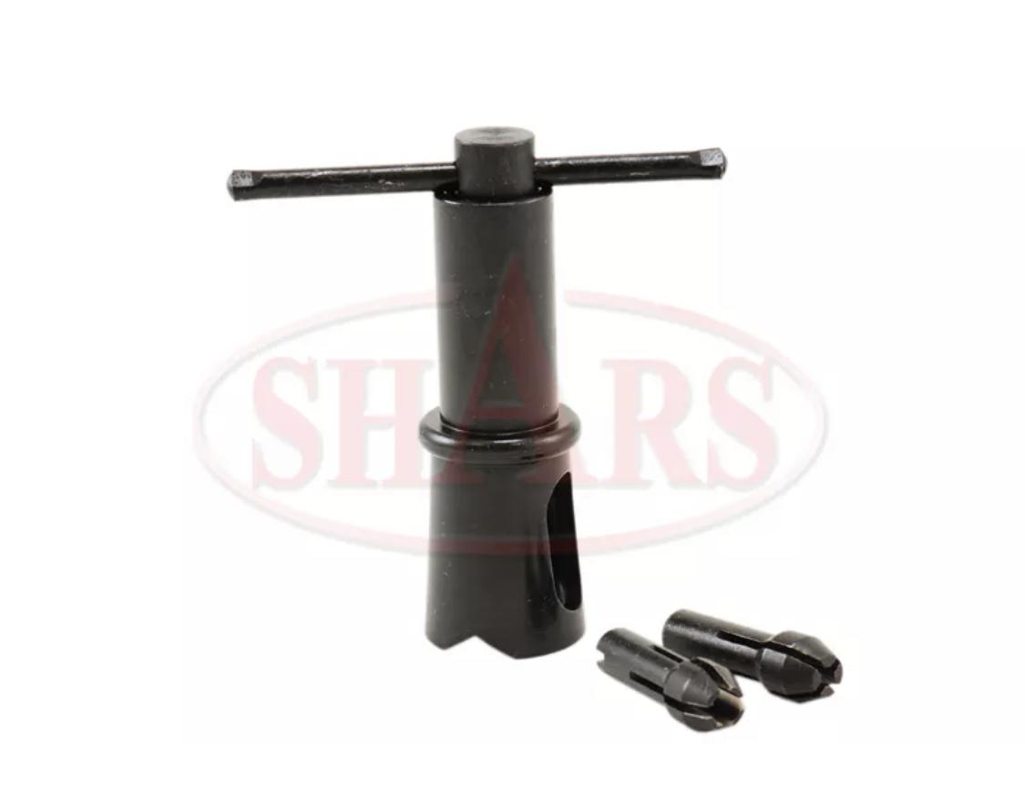
 2 pointsI somehow get the feeling that the UK and and the US are in a political "Hold my beer!" competition.1 pointMeanwhile ... on the plus side, we get this as a result1 pointThe four song EP is all here: https://www.kerrang.com/the-news/hear-the-haunting-new-a-a-williams-ep-now/1 pointeasiest to print out the file 1:1 from the gerbers. If your printer is exact, and virtually all laser printers are, this is the most accurate way. then center punch, drill, then tap.1 pointThis is one way to do it. Position the PCBs in the pattern/spacing you want on graph paper. Transfer draw holes to be drilled aligned on the graph grid. Add centerline of pattern to grid. Then cut down paper and use centerline and grid to position on heat sink and tape it down securely. Then locate PCBs on graph grid drawn holes and tape down. Use centerpunch in PCB holes to dimple heat sink to prevent drill wandering. I leave the grid paper and PCB there to act as a visual template when drilling. I use a cheap Harbor Freight desktop drill press to get the tap drill holes drilled perpendicular to the heat sink face. For M3x0.5 threads I use a 3/32 (.094) inch tap drill size. I preset the stops for a drill depth to around 6-7mm, as to not break out the other side of the heat sink. And then drill all the holes. Pull the PCBs and graph paper off and deburr the drilled holes so that the rough edges are flush with the heat sink surface. Then mount a M3x 0.5 bottoming tap in the Shars tap holder (the T handle shaped piece). Slip it into the Shars alignment stand (this holds the T handle piece perpendicular to the surface), and then using a little light lubricant, carefully hand tap each hole drilled. After each full turn of the tap, back turn 1/4 turn to cut off the internal chip. Repeat until you can remove the tap and easily screw in the length of the machine screw used for assembly. FYI, I cleaned the cheap shipping lube off the sliding parts of the tap holder because it was squeaking badly when used. Replaced with a little Never Seize and now it spins without a peep.

 1 pointIn light of recent news, the "what the fuck's wrong with me?" line seems to also apply outside the drug metaphor?1 point1 pointKevin retired from Northwestern a year or so ago, so none of those links are active anymore. Files are available here: https://drive.google.com/drive/folders/0B7egryukiT7_TFlEQlBRejdVdDQ Board files here: https://drive.google.com/drive/folders/0B_iJFfZStuVhSE5nOHBVdTByR1k Normally, the stax mafia circuit board thread, which is a sticky here, is where you find this stuff.1 pointJust wanted to share one of my most favorite acquisitions among hundreds of manual and electric tools. Heinrich deep throat is capable to punch holes in the center of 400mm panel (hello large enclosures like Modushop Slimline). No burrs, very clean holes, any hole is perfectly perpendicular to surface, and waaayy more accurately positioned than made by drill bit as you can never avoid drill bit wandering. Precision is close to CNC milling. I also use smaller punch Roper Whitney XX with smaller throat.
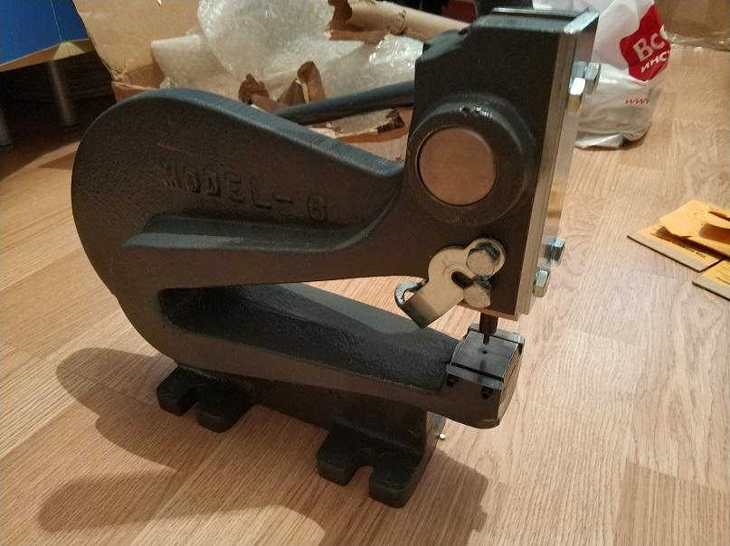 1 pointJust got this tapping guide. SHARS Self Aligning Tap Holder I'm really happy with it and thought I'd share1 point


Important Information
By using this site, you agree to our Terms of Use.