

Leaderboard


Popular Content
Showing content with the highest reputation on 09/22/19 in all areas
-
Discovered on the Gladwell Broken Record podcast, David Byrne is putting out music lists (with playback) as a radio show so checking out his covers stream... http://davidbyrne.com/radio/david-byrne-presents-under-the-covers
 2 points
 -
2 points...as opposed to water camel, air camel, or the mythical fire camel?2 points
-
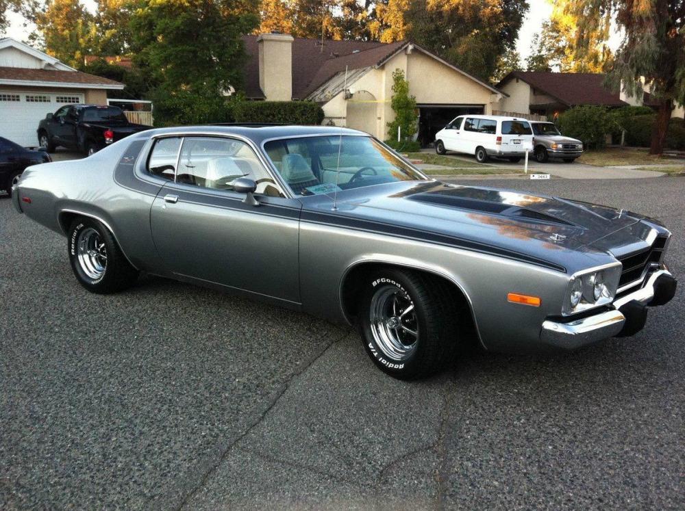
Two more then I'm jumping back to the future. Besides the collections are going South quickly. I think Mikey is on to something. I never hear it mentioned, but was there a far lesser FM killed the more regional AM star? Dusty, the democratization seems a next step (and seemingly could have even reversed the personal branding jump). As aging and personal bias intertwined here, I'll also include a shot of a vehicle I heard many of these songs in - the '74 Plymouth Road Runner. Memory is tricky, but I'm pretty sure everything sounded better on it than my current 2011 Kia Optima (Running-It-Into-the-Ground Edition).


 2 points
 -
1 pointAmazon Launches Amazon Music HD https://www.amazon.com/music/unlimited/hd Ooh , more bits ... For less .. https://www.theverge.com/2019/9/17/20869526/amazon-music-hd-lossless-flac-tier-spotify-apple Oh, Hi Neil, Pono? https://www.nytimes.com/2019/09/17/business/amazon-music-hd.html Earth will never be the same again, apparently. https://www.cnet.com/news/amazon-music-hd-launches-to-compete-with-tidal/ https://variety.com/2019/music/news/amazon-music-unveils-hd-highest-quality-audio-streaming-1203338552/ 90 day free trial. Nice.1 point
-
1 point1 pointAnd now Byrne's Nino Rota soundtracks list stream. This is a lazy mid-Sunday playlist!
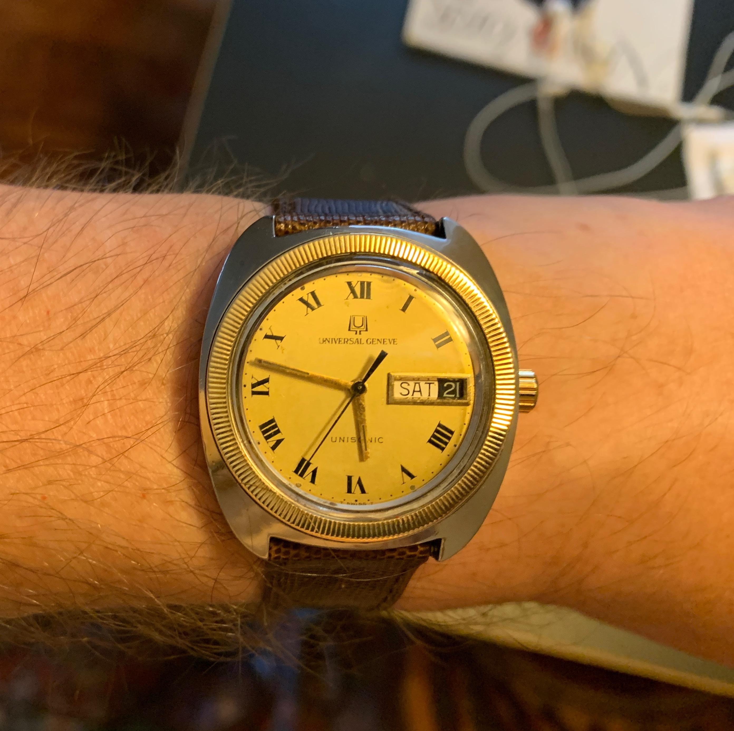
 1 point1 point1 pointI got the UG back from having the battery replaced. I do really like this watch, with its period correct 20x14 Spiedel lizard strap and gold-plated buckle.
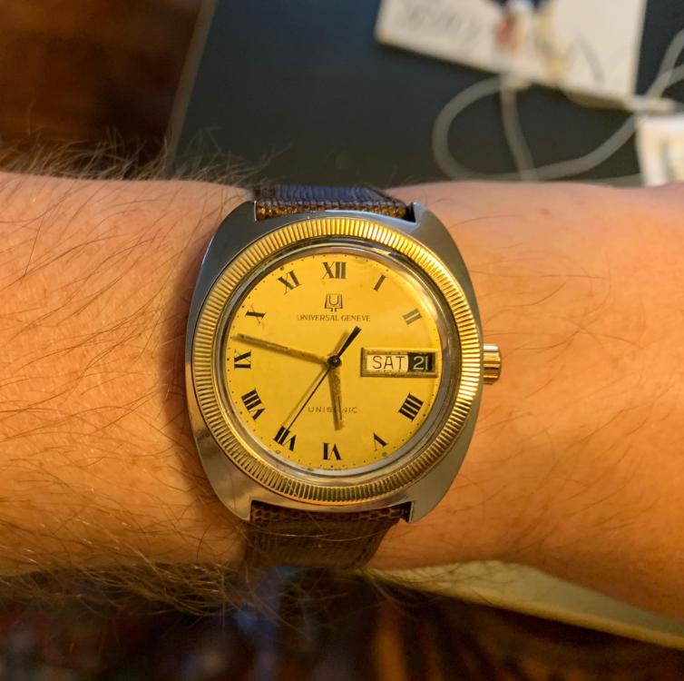 1 point1 pointBad Blood by John Carreyrou. Fabulous! Like a great thriller, once you get going with this one you can't put it down. I finished it off in two sittings. If you like thrillers, investigative journalism and good detective stories this book is for you. It is like watching a train go down the track, picking up speed as it goes, only the bridge is out ahead. As things approach disaster the tension builds, ending in a crescendo as the Journal goes public with its story and the house of cards starts to fall. I remember reading the Author's contemporaneous reporting on this and being blown away at the lack of scientific and medical rigor and that it hadn't raised red flags in the minds of the extremely influential people associated with the company. I have the same feeling after reading the book. Absolutely recommended. EDIT: After the events of the last few weeks I can't wait to read a similar book about WeWork. ?1 pointI distinctly remember that leap of better music going from cheesy am shit —Captain & Tenille, Paul Anka, Neil Sedaka— to FM coolness when I got a better portable radio. I don’t think it had anything to do with am vs fm or audio quality, I just liked the programming of that station better, but in my child’s brain, I thought it was fm.1 point1 pointBlue hawaii build notes based on kgbhver6sbipolarinc. The amp board is fairly easy to build, but I do have a few observations 1. EITHER populate the LSK389 6 pin dual transistor OR the two single transistors each side NOT both EITHER populate the STN9360 smd transistors OR the KSA1156 just below them NOT both important and high voltage tracks run close to the screw holes for attaching the heatsink L brackets to the board on the top side of the pcb. I would be very wary about placing the L bracket on this side, if the solder mask is rubbed there will be a short to the L bracket which is probably electrically connected to the rest of the case and the case is probably connected to earth (certainly in countries with 3 pin mains leads) and that’s going to be bad.... 2. the tube sockets and trim pots go on the other side of the pcb to the rest of the components. If you want you can also put the leds on the top side so you can see what is going on. The 3 leds will give you an indirect indication of the status of the board. All 3 leds should be lit for normal operation. The led by itself gives an indication of the -400V line, the two leds closer together indirectly show the state of the +-15VDc lines. There is no led for the +400V line. 3. to set the constant current to 20mA you need to measure 1V DC across the 50ohm resistor near the trimpot (one for each valve). Since the trim pot is on the top side of the pcb it makes sense to put the 50ohm resistor on the top side two. I raised the resistor off the circuit board so I could easily clip insulated multimeter probes to the leads. 4. I found mounting the screw terminals to the underside was a pain in the ****. it may look neater BUT to screw the terminals you have to get to the underside of the board. BUT the pcb is mounted to an L bracket mounted to a large heatsink. So, you either have to flip the entire thing over.... hope you have long enough wires to allow this OR put the entire thing on a desk and stand on your head and screw upwards from below.... I am sorely tempted to desolder the screw terminals and mount them on the top of the pcb. 5. if you are going to have a single ended input to the amp e.g. RCA/phono then the -input should be connected to the ground for minimal hum. 6. when you are doing the inter board wiring for the first time make sure the inputs are shorted to ground. I got some instability issues because my input wiring was too close to either the stax output socket wiring or the main transformer and had nothing connected to it and was not shorted to ground. 7 when you build the amps boards set all the trim pots for halfway and verify with a multimeter in ohms mode. This will save you from having a trimpot at one extreme of its travel and result in LARGE DC offsets or high constant current pull.... 8. if you have a scope or two multimeters it’s much easier to set up the amp because changing the DC offset also makes the balance change and vice versa. With a 2-channel scope or 2 meters its far easier to chase the correct spot. Adjust the two trim pots near the 50ohm resistors have been adjusted for 1V across the resistor i.e. 20mA current, first. Next you can adjust the dc offset and balance between the valves, the audio inputs should be shorted to ground and no headphones attached for all setup. If you are using a scope make sure it’s set to DC coupling... AC coupling will ignore any DC offset and its DC offset we are trying to null out. Also, if you have a scope do no connect the ground terminals of the probes to anything only the centre pin of the probes is needed. (almost all scopes internally are grounded via the main input) almost all multimeters are NOT and require the ground lead connecting to the amp board or psu ground. 9. Im my experience if you are building a single box amp, even if the transformer has a magnetic shield foil, putting the audio input wires anywhere near the transformer will result in hummmmmmm..... the magnetic field is STRONG with this one... 10 The hottest transistors on the blue hawaii are the FQPF8N80Cs, measuring the mounting screw of the transistor - (which seems to be the hottest part I can find) I get a stable 65C after multiple hours of use, this is using arctic ceramique thermal paste, aluminium L bracket 200mm by 80mm heatsink with 40mm fins and aluminium oxide insulation pads.... 20mA constant current and +-400VDC B-+ 11. double check which trimpot you are adjusting. I have adjusted the constant current trimpots by accident when trying to do DC offset and balance multiple times.... 12 some labelling of the trimpots to say what does what on the silkscreen would be nice... 13 labelling the screw terminals on the top side of the board would be nice for checking wiring after the boards are in place. I hope this is useful James1 point1 pointBlue hawaii build notes for the kgsshvpssicfetdual2new PSU The kgsshvpssicfetdual2new is based on version 1.6 of the kgsshv psu single boards and does NOT have the cpc1117N or resistor required for simple B+,B- delayed start. (it’s still possible to implement delayed start but it requires a relay(s) which the cpc1117N avoids). In all other ways its similar to the v1.7 single boards. The single boards put the b+ on one board and the b- on another and split the -+15V and bias between them. The kgsshv ps dual has all the dc voltages required to power the blue hawaii and apart from the notes above is topologically and componentry identical to the single psu boards. The notes bellow applies to BOTH the single and the dual psu boards. Construction is straightforward other than 1. the silkscreen shows 15-0-15VAC input for the + and 15VDC outputs, Since the -+15V output is a simple DC supply with a bridge rectifier and voltage regulators 15-0-15VAC is NOT sufficient to provide -+15V output... I have verified this using a variac. There is about 0.6V drop across each diode in the bridge *plus* the voltage regs need between 1V and 1.5V more input DC than their output in order to regulate properly. so 18-0-18AC is actually required to get a properly regulated -+15VDC output... Any more VAC input will be converted into heat by the voltage regs. However, with 18VAC-0-18VAC centre tapped input the voltage regs run very cool with the small heatsink they are bolted to. 2. the blue hawaii amp boards -400VDC lines draw more current than the +400V lines. If you connect a single channel up to the psu board for testing there will be no problems. Connecting two channels results in the -400V line on the psu going into current limit and the voltage dropping to (im my case) about -175VDC. The fix is fortunately easy. The 5.1ohm 3W or 5W resistors are the current sense resistors for the over current protection. On the -400V psu side either replace the 5.1ohm resistor with about 2.6ohm or similar wattage and type or parallel another identical 5.1ohm around the existing one. The +400V does not need modification. the lower the resistors value the more current supplied before the current limit cicruit activates. I don’t have anyway to variable load a line that has such a high voltage but I would guesstimate that the 5.1ohm resistor current limits at about 100mA since two amp boards +400V together draw around 81mA and there is no problem with 5.1ohm and 2 -400V boards draw between them around 129mA and that causes current limiting with 5.1ohm sense resistors. 3 make sure none of the metals tabs on the transistors are shorted to the heatsink/L bracket that mounts to the heatsink. Use electrically insulated spacers between the back of the transistors with metal tabs and the L bracket/heatsink AND use a nonconductive gromet to insulate the bolt from the transistor. The psu transistors do not get that hot with a reasonable size heatsink attached. 4. if you are building in a u2 high case the largest main psu caps you can put in are Kemet 500V 470uF long life at 65mm tall. Beware they also do an 80mm tall 470uF cap - this will NOT fit in 2u. Similarly 680uF caps at 500V are 80mm high and will not fit. 5. if you want to check the bias is 580V use the bias test point. Dont measure at the bias screw terminal. Why, typical multimeters have a 10M ohm input impedance and assume whatever they are measuring across is much less than 10Mohm... this is NOT the case for the bias line which has a 4.7Mohm resistor. result the multimeter will NOT give the correct voltage reading between the ground screw and the bias screw. Measure from the bias pad nearby to the ground screw. Also, don’t measure the bias with headphones attached. 6. there is only one screw terminal for +400V, -400V, +15V and -15V so you will need to connect two wires to each screw terminal. This limits the gauge of the wire. Also make sure you are screwed the terminal down well, its easy to have one wire firmly affixed and the other one lose.... 7. to adjust the B+ and B- lines the two 390K resistors (R8 and R9) in series with the 20K resistor (R7) just after the 1N007 diode that have the 0.047uF cap across them need to be changed. Approximately (for my psu) I got the following 442K for 450VDC (note requires a transformer with 360VAC output to have enough voltage input to get proper regulation) 390K for 404VDC (transformer 330VAC or more output) 365K for 375VDC (transformer 310VAC or more output) the approximate equation for me was the total of the 2 resistors in ohms/(20,000-700)*10 (the 20,000 is the resistor in series with the resistors you are changing, the 10 is the output of the voltage reference LT1021-10), the 700 is the fudge factor to make the numbers accurate for me... (variation in voltage reference, variation in the 20K resistor etc etc...) 8. To test for proper regulation connect a volt meter to the nominally +-400V output and a ground screw terminal and either power the transformer from a variac OR if your variac can go high enough you could go from the variac output into the 300VAC input of the psu. There is no need to have amp boards connected at all and its safer if you dont. Slowly increase the AC and you should see the DC output rise. At some point increasing the variac by some volts will result in very small output increases (in the order of few milli volts) now the psu is regulating. Measure the 330VAC input of the psu and that’s the minimum transformer output voltage you need for regulation. Both the + and - 400V sides of the psu should have similarly behaviour and similar minimum VAC input requirements since they are almost identical in topology and are identical in components. 9. I would recommend initially testing the psu board without amp boards connected in case voltages are way off. However, with no load on the psu the b+ and b- lines, they will take some minutes to fall to 0v and with no headphones the bias line will stay high for a long time. Fortunately the bias line can be discharged just by connecting a multimeter to it and ground and set to DC volts. Even a meter with 10Mohm input impedance will drain the bias line in a few minutes. the -+15V lines will be drained by the voltage regulators. 10 I would recommend a variac for initial testing it allows you to bring voltages up slowly and make sure that voltages are going up in symmetry (-+400V, -+15V) and becoming stable. 11. If the outputs look good with no amp boards attached, connect one board and repeat the tests. Better to put in channel in danger than both... especially if the amp boards have not been tested. 12. if test with the other amp board only. You don’t want to blame the psu if one amp board only is miss behaving... 13. test with both amp boards. Remember if the -400V line goes down in voltage significantly only with 2 amp boards attached and is fine with one you probably have a current limit problem and did not implement item 2 here! 14 don’t plug in headphones unless 1. you have a spare pair you don’t mind frying. 2. you have tested voltages, dc offsets are nulled and you are happy. ideally look at the outputs on a scope and put some sine waves in.... 15 Before you plug in anything visually inspect for solder bridges... I had a partial bridge it only started conducting when the input AC to the psu went above about 26VAC... thank you variac... 16 use probes with insulation, there is lots of high voltages don’t short out things with you probes.... 17 Before you power up anything double check the wiring the - and + on the silkscreen are quite small and you dont want +400V going to a place expecting -400V.... 18 temperatures are low, with the psu attached at a 200mm by 80mm heatsink with 40mm fins, (both amp boards running constant current 20mA and -+400V B-+), the centre of the case of the +400V side transistors are about 40C, the -400V transistors are around 3C higher at around 43C. The cases on the C2M1000170D transistors take some time to become as hot as the mounting screws. The 10M90S cases reach the mounting screw temperatures far faster. 19 I know the board has been made as small as possible and around the screw terminals its rather crowded. But it would be nice if there was sepertate screw terminals for the -+400V and -+15V for each channel, this would allow for the use of thicker wires and reduce the possibility of a wire comming out. (I have already had the situation where I though both wires where screwed in tightly to a single terminal and then one came out) Hope this is useful James1 point1 pointI have one again tried to get by with a video card on air.. But I hate dust busters, so had to order a water block and throw together a loop with what I had around. The sound of silence!
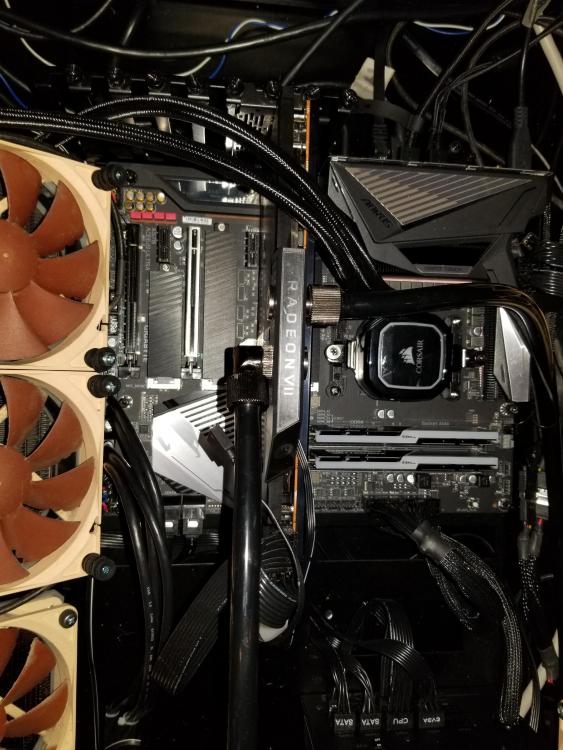 1 point1 point


Important Information
By using this site, you agree to our Terms of Use.