

Leaderboard


Popular Content
Showing content with the highest reputation on 06/20/21 in Posts
-
3 points
-
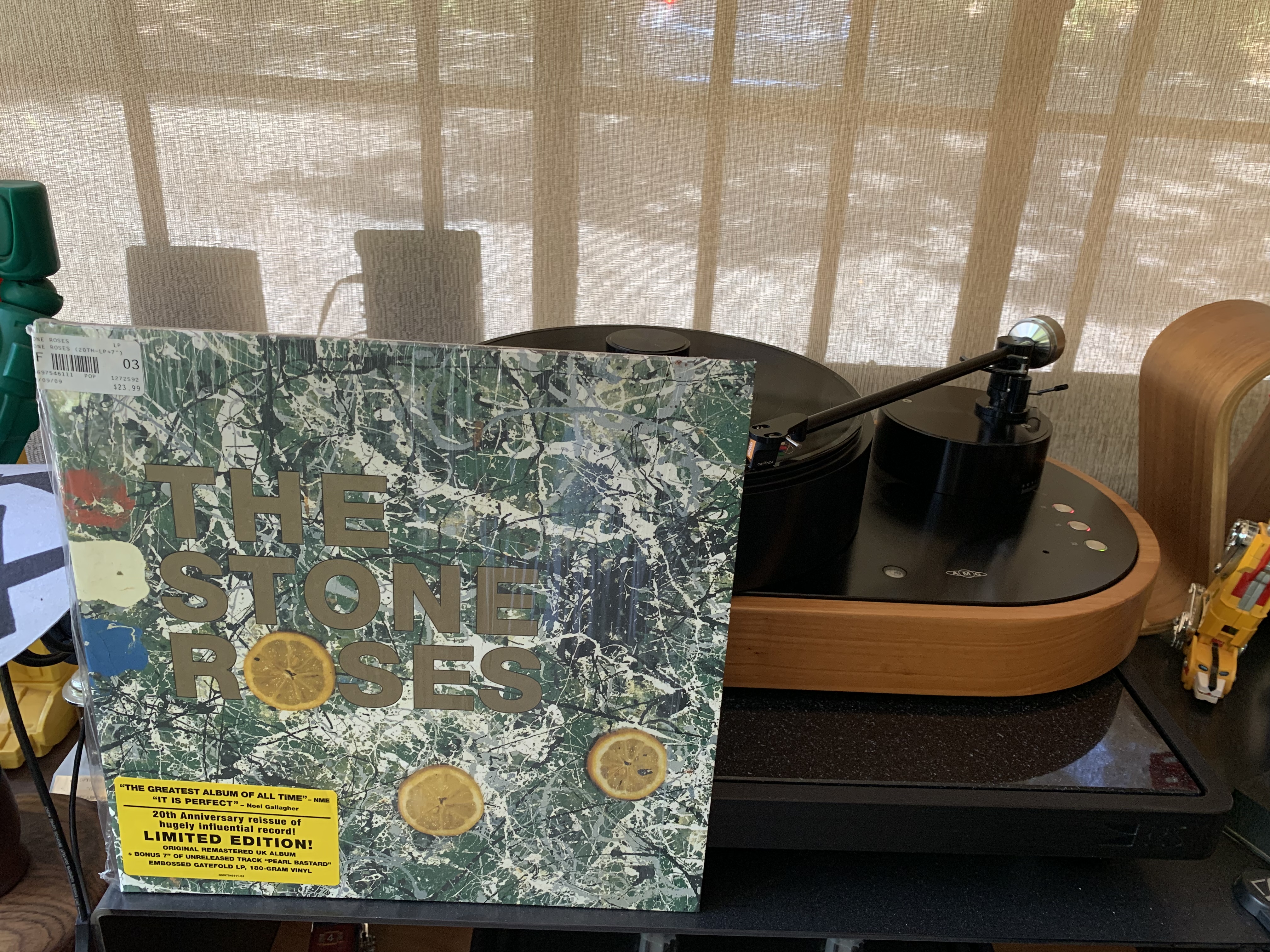
2 pointsOne of the best albums ever recorded. I have it on vinyl, twice (old original and new 180g reissue), on CD and ripped to NAS, and on Tidal HiFi. Recorded the same year as Carol King Tapestry.2 points
-
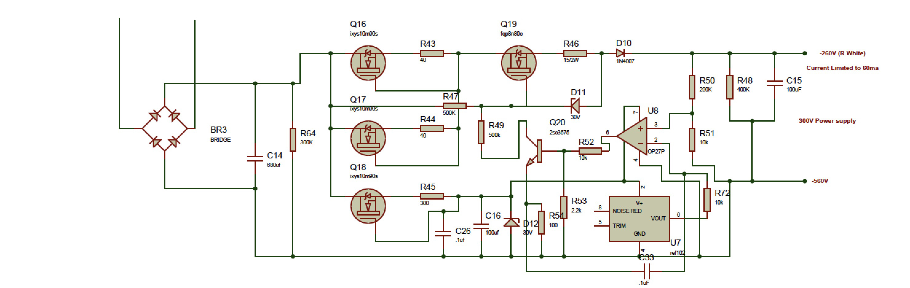
2 pointsDon’t worry about Q16 and Q17 since you are getting about 425v out of the regulator. If you are getting 30v across D12 then it says that Q18 is most likely working. If you report back on that it will be easy to figure out next steps.2 points
-
2 pointsanother possibility is to either change the voltage set resistor or parallel it so that the voltage is lower. I do this on initial testing of high voltage rails. I generally parallel to get about 50 - 100V output, use a variac and check it regulates close to the expected output voltage. This reduces the voltages and if something does go wrong there is more chance of more components surviving... but as I say each to their own problem solving style.2 points
-
2 pointsWell I wouldn't even try. But then I'm a stickler for doing things by the manual, and believe in the maxim RTFM. I think that doing inter-comparisons between bits of circuit is likely to confuse rather than illuminate. The best way to test the circuit is to run it and very carefully measure voltages (because they are high, and deliver substantial currents) and compare with what is expected. Just don't slip with a probe, because it might spoil your day. To keep from generating frightening sparks and dead silicon, I have often soldered on stiff short lengths of wire as temporary test points and use those to clip to. Once the fault is diagnosed, they can be desoldered.2 points
-
2 points1 pointI don’t ground the PS to the chassis because there is a switch on the amp board that ties ground to the chassis or can leave it floating.1 point1 pointThat’s great news. Congrats. I just use resistive loads mounted on heat sinks. Make sure they can handle the power and voltage.1 point1 pointThat will do. Take it from one of the positive rails. while you’re at it, double check the value of R72 and confirm continuity of the ground pin for the reference.1 point1 point1 pointGreat! Looking at your measurements of ref102 I suspect you might have the problem there. You should have a potential at Out (pin 6) of 10 volts above -562V - that will be -552V and not -532V. You have a spare ref102?1 point1 pointMay I suggest a diode test comparison Q20 against Q15 to exclude the 2SC3675? If not already done.1 point1 pointYou can and I have/do. I agree its not 100% reliable in circuit and I know it was not designed to be used testing in circuit. In some cases it will not be consistent when identifying a transistor because the circuit puts it close to the edge case for a recognition and probably has zero input protection but I still have and do find it useful in circuit. Its useful when you have two identical or near identical circuits. You can make comparisons and it at least narrows down what you might have to desolder. In some cases the circuit around the transistor effect the behaviour of the transistor so its miss identified or is right on the border of identification (as stated in the post above). But quite often it will identify correctly and I have never had it identify a bad transistor in circuit as good... its just another tool to be used on special occasions when you know what you are doing and you have to think about the results. For example when testing one of two individual transistors wired as a Darlington pair can identify the single transistor as a darlington. But again if it does the same identification with similar gain on both the good and bad rails then those transistors are likely to be good etc etc. I prefer testing this way than desoldering all the transistors and checking them all. But different people go about problem solving and troubleshooting in different ways. When I know it identifies a transistor correctly and consistently in one circuit and identifies the corresponding transistor in the other rail as two back to back diodes or says the gain in the good rail is say 100 and the gain on the other transistor is 2 then that transistor is suspect and a candidate for pulling and further testing.... (all of which I have experienced) Its more limited when you can't make comparisons between known good and known bad, but if it correctly identifies a transistor type and pin out then a quick look at the schematic for possible other transistors nearby it could be identifying instead then you can be reasonable certain that transistor is ok.1 point1 pointYou can't use a Peak DCA75 to test in-circuit. It says so in the manual.1 pointMozart: Violin Sonatas on Oboe Olivier Stankiewicz, Jonathan Ware 2021 Example:1 point1 point50 Reasons to Love Joni Mitchell’s ‘Blue’ Mitchell’s “Blue” exists in that rarefied space beyond the influential or even the canonical. It is archetypal: The heroine’s journey that Joseph Campbell forgot to map out. It is the story of a restless young woman questioning everything — love, sex, happiness, independence, drugs, America, idealism, motherhood, rock ’n’ roll — accompanied by the rootless and idiosyncratically tuned sounds she so aptly called her “chords of inquiry.” https://www.nytimes.com/interactive/2021/06/20/arts/music/joni-mitchell-blue.html?referringSource=articleShare1 point1 pointYou may have done some of these tests already but for the -260V output (i.e. 300+ above the -560V rail, -1 inspect carefully for solder shorts, joints missing solder etc. 0. I would check the AC voltage going in is what is expected. 0.5 check dc voltage after bridge rectifier and smoothing cap is what is expected. 0.6 check the input side of the pass transistor Q19, if Q19 only has say 145V on the input side then it cant be expected to output 300V... 1. I would connect to a variac and see if the psu is actually regulating at 134V or if it varies with input voltage 2. I would check the voltage reference is outputting the correct voltage 3. If the op amp is in a socket I would swap it out for a known good one 4. I would check the voltage drop across the zeners diodes and check the value of the resistors in the voltage divider that sets the output voltage 5. if you have a peak dca75, de-solder the transistors and run an identify on each. I have found that most of the failed transistors I have tested on the dca either show up as back to back diodes, shorts or open, or crazy low gain compared to the spec. 5.1 although not as reliable, you can use the dca in circuit without desoldering the transistors first. Make sure the circuits are not powered and the reservoir caps are fully discharged before running any in circuit tests. if you run dca75 identify tests on the transistors on a known good rail and compare to the corresponding transistors in the bad rail. Any major differences may identify that component as a possible issue, since the rails have identical topology and the low voltage behaviour of all the transistors in the rails should be approximately the same. Do expect some identification fails (device not recognised or no device connected) since you are testing in circuit. But at least it gives you a point of comparison and can be quicker and safer than desoldering... good luck I have not used the DY294 in circuit, I certainly would not advise using any of the breakdown modes in circuit because the voltages used could easily over volt components. The peak dca75 identify function seems to be quite "gentle" and I have used it in circuit on various golden reference lv and hv boards, blue hawaii amp boards etc with no ill effect. Diode testing the transistors is also an option but I have found transistors that have failed but pass the multimeter diode check because they have failed in such a way that they now act as diodes with zero gain. In this respect peak dca75 identify is better. But multimeter diode check is better than nothing. NOTE any depletion mosfets may diode test as shorts or near shorts since depletion mosfets are fully on by default unlike enhancement mosfets...1 point1 point1 pointNope, just reading... but not getting any wiser. Faulty FQPF8N80C mosfet or IXYS regulators, desolder and testing in the DY294 or measuring while on the pcb? Finishing the teflon output wiring in the mean time.
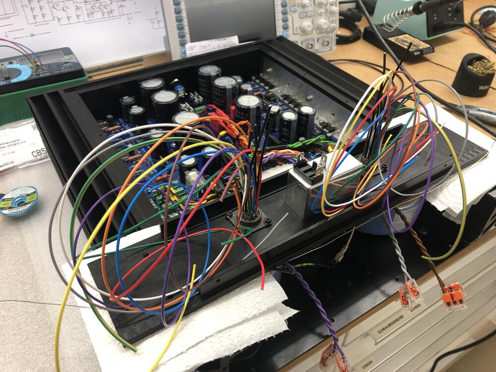

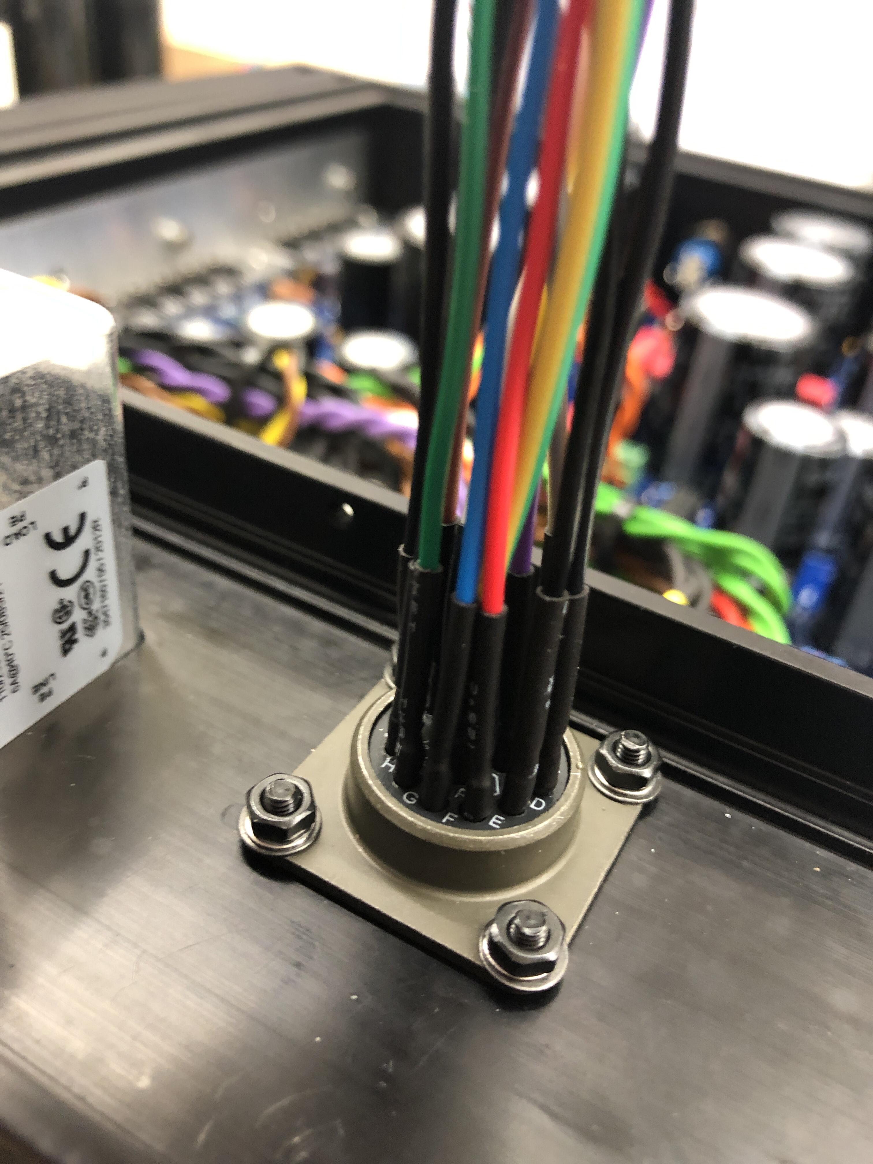
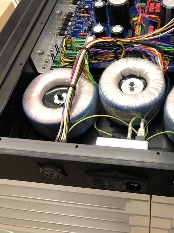 1 point1 point1 pointTest Tone @ Home live right now: https://mixlr.com/illuminator/1 point1 point1 point1 pointI have to say that even though some of their ideas were overlooked due to other formats, that doesn't mean that they were inferior. I had a Sony ES HiFi betamax deck in the 80's. It cost me an astronomical $1,100.00 at the time. But with it's ability to record and play in beta 1 speed and it's jog/shuttle dial, that machine kicked some serious VHS ass! I had a JVC HiFi VHS deck too. I'd rent movies in VHS, because there weren't any betamax movies to be found. But I'd record those movies onto the betamax. I'd also record music onto betamax tapes, then use it like a real to real to play hours of music at parties. That kept people from screwing with my audio system.1 pointThey're just Nylon R Type Cable Clamp Fasteners. I got my last batch from Amazon. I tend to use 1/8, 3/16 & 1/4" sizes.1 pointHi @Kerry, nice build as always. Mind sharing the p/n for the white clips holding the pot cables to the PCB spacers? Thanks a lot!1 point1 point1) I think so, but I don't remember at this point. 2) just make sure the bolt does not touch the top and the bottom of the chassis at the same time. otherwise you get a shorted turn and that is real bad. if you use the Teflon wire and pre-tin, makes it much easier to do the amphenol connectors. at least 1 hour each.1 point0 pointsFor -500 and -560, I am measuring -501.14 and -562.1, both are absolutely stable. The -260 measures -134... -135 and fluctuates in the .1 range Checked all resistor values, orientation of diodes, etc. The 2SC3675 I measured before soldering. The IXCP10M90S and FQPF8N80C I didn't check as they were straight off Mouser. Not measuring any short for any of the heat sink mounted devices. Any hints as to where I might start looking first?
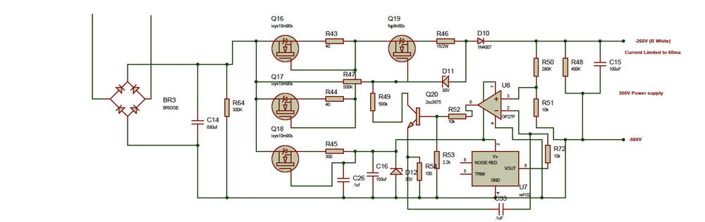 0 points


Important Information
By using this site, you agree to our Terms of Use.