

Leaderboard
-
shellylh
High Rollers10Points18862Posts -

tyrion
Moderators5Points10806Posts -
Grahame
High Rollers5Points16722Posts -
kevin gilmore
High Rollers4Points7204Posts

Popular Content
Showing content with the highest reputation on 10/14/21 in Posts
-
Feels appropriate to leave this here: Pokemon x Grado collab! That is a line I never thought I'd ever write. Life is indeed stranger than fiction sometimes. https://blog.gradolabs.com/pokemon-center-grado-headphones/4 points
-
4 pointsMy previous dust collection system didn't use cyclone technology. At that time spongy membrane technology was the state of the art.
 4 points
 -
2 points2 pointsThe Sea Shanty singing version of William Shatner? https://www.theregister.com/2021/10/13/shatner_space_flight/ A Rocket Man for sure ...2 points2 pointsJust a reminder... https://www.theonion.com/interim-apple-chief-under-fire-after-unveiling-grotesqu-18195722112 pointsmore parts stuffage the wire used to hook up the power led inside the switch is pure silver wire from the US military in 1965. the rest of the wiring will be silver plated copper teflon.
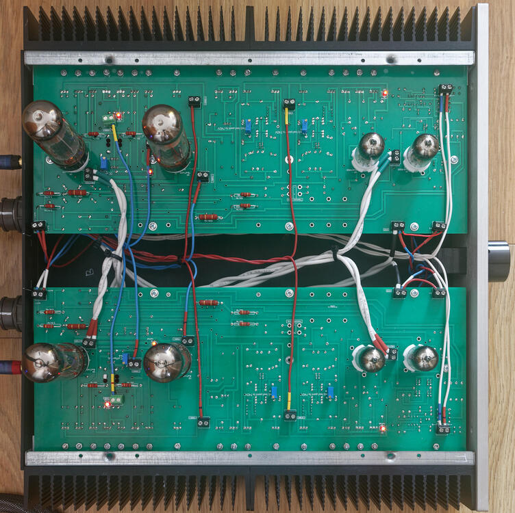
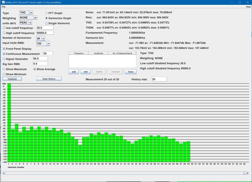
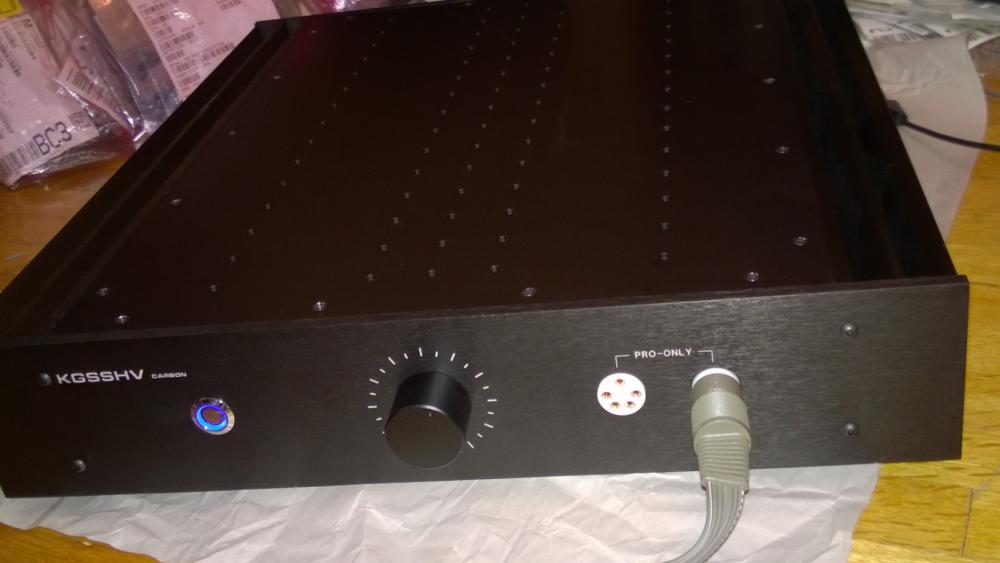
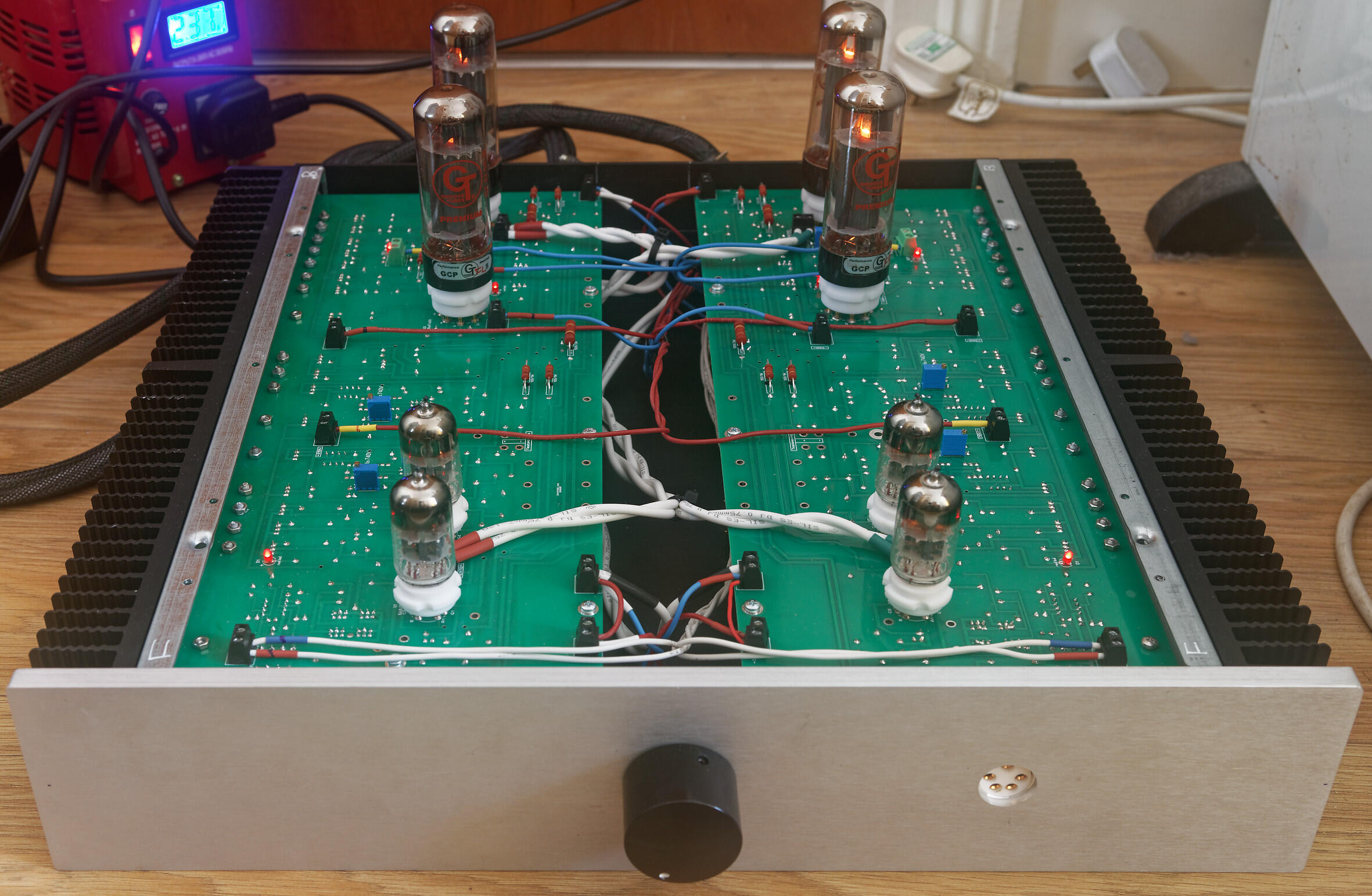
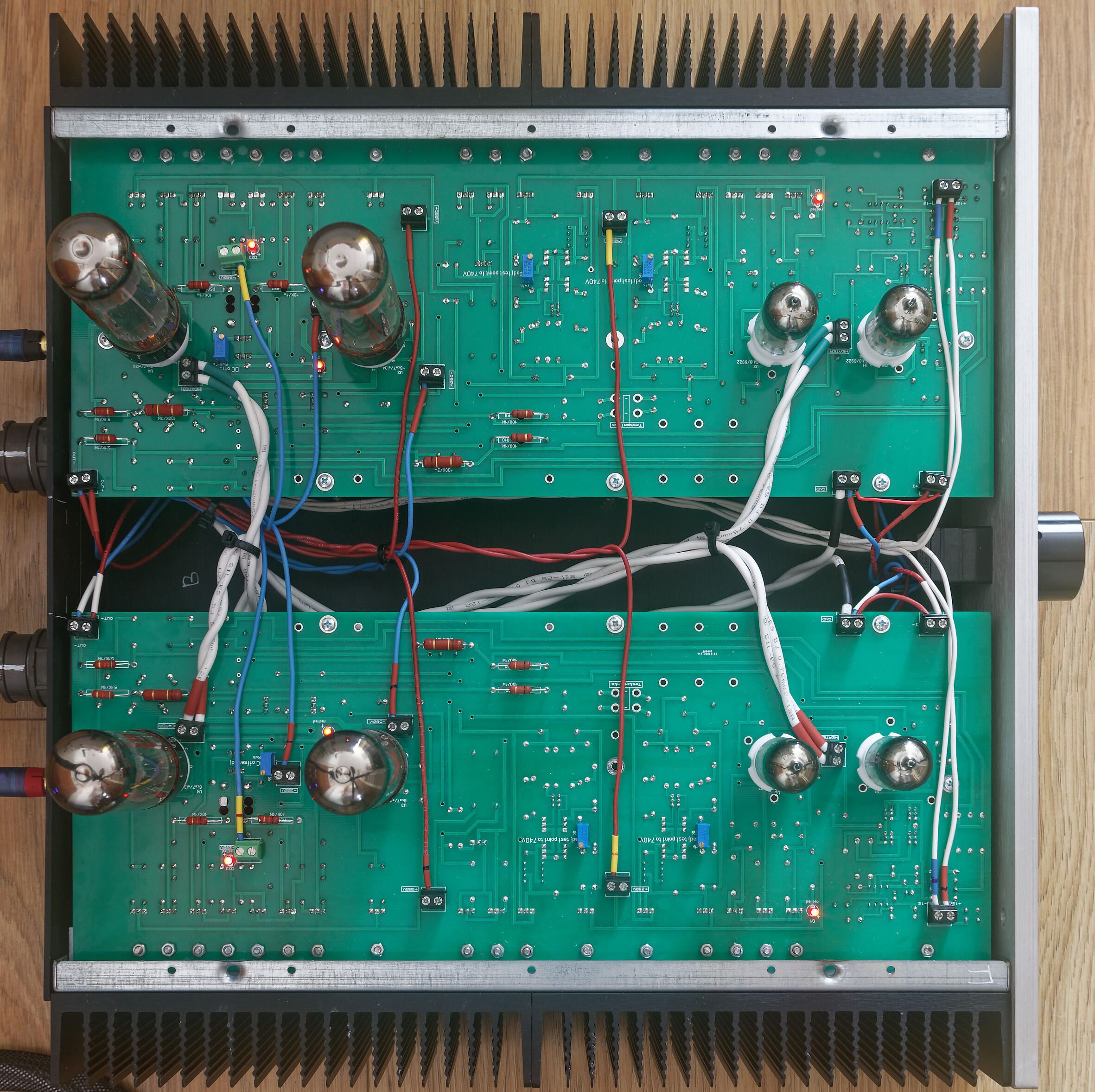
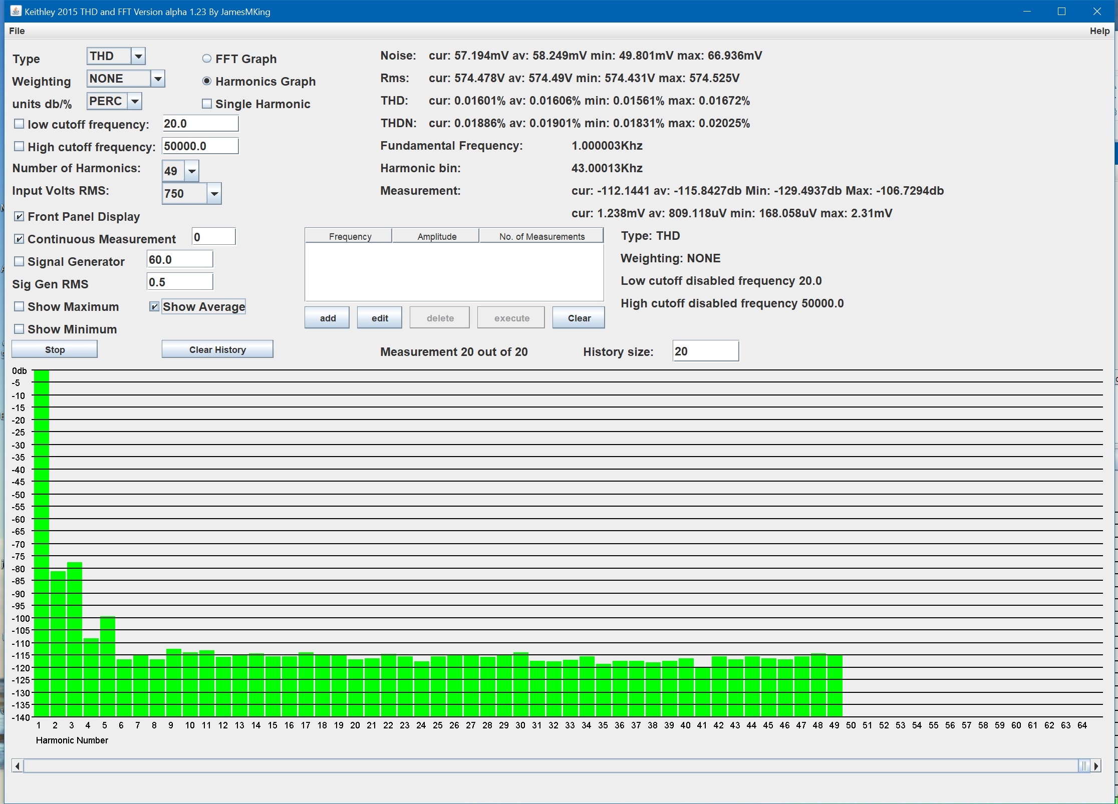
 2 points1 point1 pointRoad to the Sun Pat Metheny 2021 Really a masterful album:1 point1 pointthis is a put together chassis of a specific size. where he bought the chassis i do not know, but it completely comes apart, all 4 sides, the round corner pieces etc. Then he had the front,back and top all machined. all panels are .2 inch thick. And the front wood piece is esentially a stick on made of unknown wood. absolutely every single thing about this is fucked to the max. broke the anti-spin pin off the pot and did not even bother to drill a single hole to prevent the pot from spinning. Some of the work was definitely done by an nc mill, and a really shitty one at that. on the mill i used, everything was accurate to .00001 inch, and it really was at least this accurate. this thing is barely accurate to .008 inch. nothing on either inch or metric boundaries. and the holes for the power supply board were drilled by hand, and blind tapped, 2 of the 4 holes went all the way thru the panel. But the worst is the way under-rated power transformers which were potted with definitely the wrong stuff. And wiring all the filaments together. And the stax jack it turns out is also massively fucked. And force held in with rubber o-rings. Gold plated hex screws with the gold coming off. And the tube sockets were really low quality garbage, as bad as the russian crap that mikhail used. The 3 boards from jlcpcb were a total of $65 with shipping. and shipping was half the price. The hand dremel tooled boards were so utterly fucked, no reason for any of this. Somebody really high on really bad drugs did this. Not even mikhail or mike bean (hennyo) could do something so utterly and completely fucked. Wow, i gave hennyo a compliment, yikes. The 300v tube supply is actually pretty clever and kind of unique, but also utterly fucked because he had the pass tube cathode wired to ground when it had to be connected to 300v. And the bias supply with a 100k series resistor. Guaranteed to kill your headphones. Its not my money going into this, so i will continue till its either completely finished and working or the tube diode power supply cannot be made to work. Looks like the repair price will be about $1500 in parts, plus the original purchase price of about $5k. All the improvements to the amp board are in the new board. There are places for solid state diodes on the power supply just in case. There is no reason for any of this. So far i have about 30 hours of labor in this. The mikhail es1 ended up about 50 hours of labor. Yes i'm fucking nuts. all you have to do is take my board files, have them made, stuff with parts, slap into chassis. how fucking hard can it be.1 point1 pointlisten to it? if you check my todo list nowhere does it say listen to it... measure it yes... listen to it? why would I do that? 🙃 latest update, internal signal wiring done (silicone not cardas - I need to buy more cardas chassis wire) and front panel completed. Both channels powered up at the same time for the first time. No drama so far. The heatsinks around the el34s runs a bit hotter than joamats mini T2. I not done any temperature checks look good. All transistors seem ok and so do the high power resistors. .6922 heater voltage is a little high at 6.35V so I will need to add some dropper resistors. All other voltages are spot on. El34 heaters are at 6.1V which is about the same level as my mini T2. I found my first issue, the DC balance between + and - halves of a channel is fine <50mv BUT the DC offset to ground started at -85V and even adjusting the offset pot all the way I only got it down to -33V. Exactly the same on the other channel due to close matching of components and matched valves. So I will need to replace the dc offset adjustment trimmers with something 2-3x the range. Anyway I know you have been waiting for the money shot: glowing leds and heaters so enjoy: Im currently going for an extended power on idle test and will be periodically checking voltages and temperatures on both the amp board and psu. If that passes it will be time to feed it some test signals... I hoping for more detail in the square waves, more dynamics in the triangle waves and smooth fatigue free sine waves. Here are the first measurements. Distortion 1Khz input Total Harmonic Distortion to 49Khz is around 0.0063% unweighted (average of 20 measurements) 2nd harmonic is around -90db and third slightly higher at -87db. The other harmonics are very low all less than -105db. total harmonic distortion plus noise is better than 0.018% (im not using shielded cables for this test AND the amp and psu do not have top lids and the cases are not grounded so the amplifier is almost certainly has better thd+n than I am measuring in this setup. At around 575V rms 5th harmonic starts to rise and at 600Vrms output all harmonis increase and odd order are higher than even order harmonics. NOTE this measurements where taken with around 35V DC offset so it is possible clipping may occur a little later with less offset... Noise, THD, THD+N and level of distortion harmonics at 575V RMS, 1Khz output: Noise, THD, THD+N and level of distortion harmonics at 600V RMS output 1Khz: The THD up to 49Khz is still less than 0.05% The amp runs quite a bit hotter than the mini T2, heatsinks near the EL34s run at 40C and power consumption is close to 205W. The mini T2 is around 153W. The power supply is also is less efficient than the golden reference HV, the 3W resistors between the ksa1156es and ksc5026 run close to 90C and dont have a lot of room around them, on one side there is a large 0.1uF 1KV film cap and on the other 5 closely packed transistors... So the T2 needs good heat sinking and the psu boards could do with lengthening a little to give the 3W resistors a little more air flow around them and drill holes under them. Update DC offset fix, The 5K pot in parallel with the 510 ohm emitter resistor gives a minimum resistance of about 461ohm which still gaves me ~ -33V offset. With the 5K pot in the middle you get around 423ohm combined resistance and ~ -85V offset. So I replaced the 510ohm with 604ohm and this gives enough adjustment range to get <1V DC offset. (I would have implemented joamats suggestion but I did not have any 10K pots)
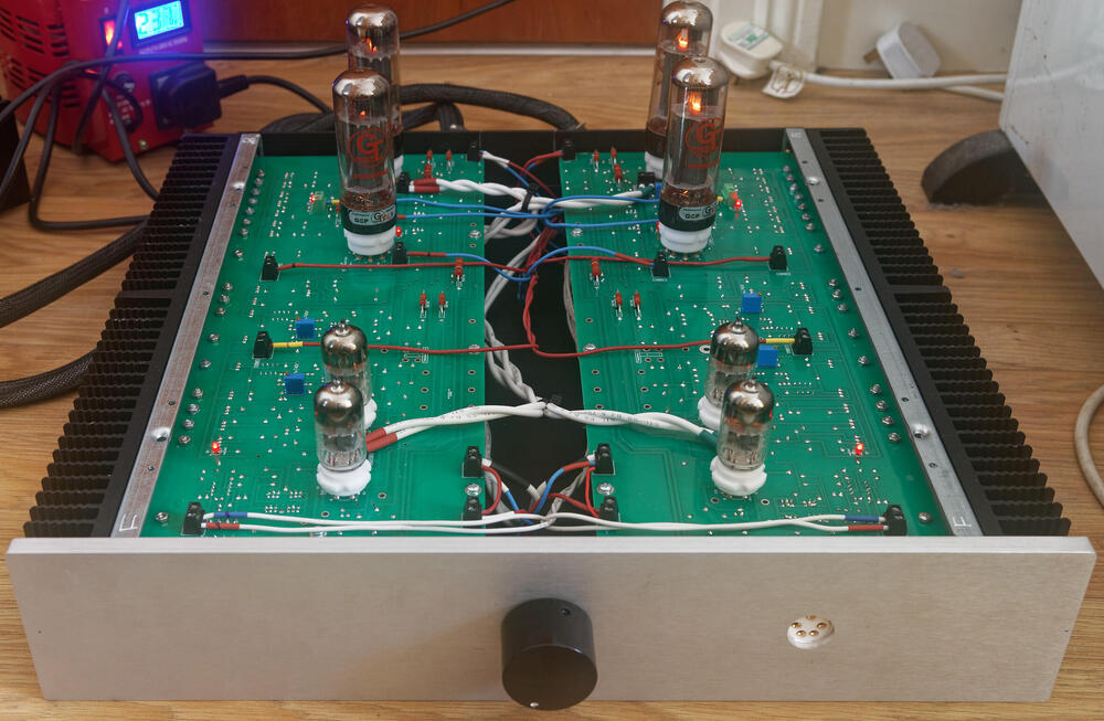

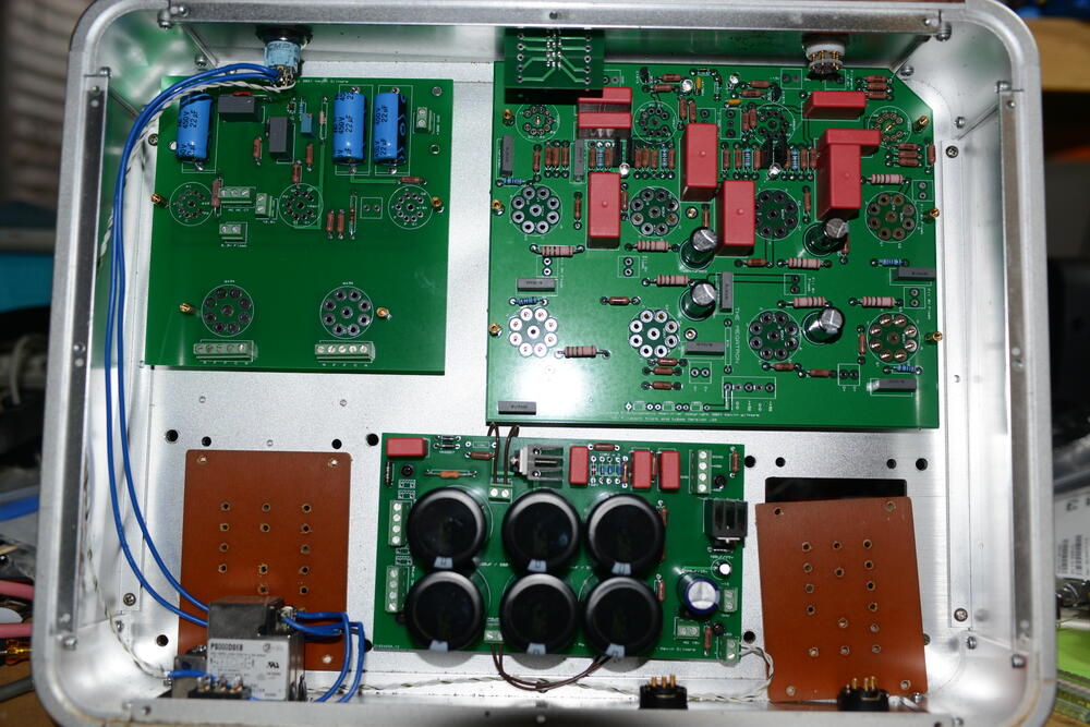
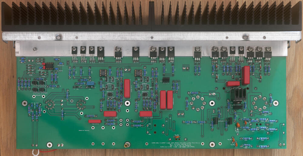
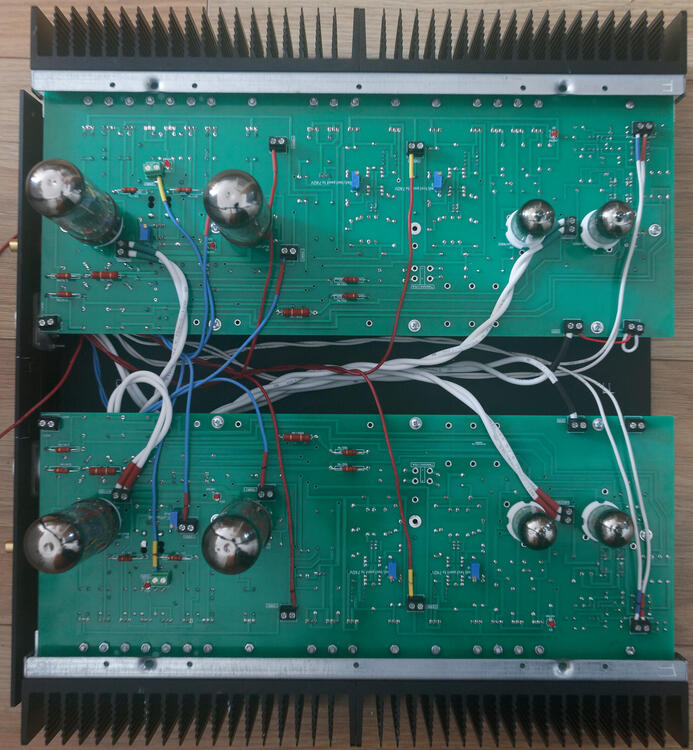
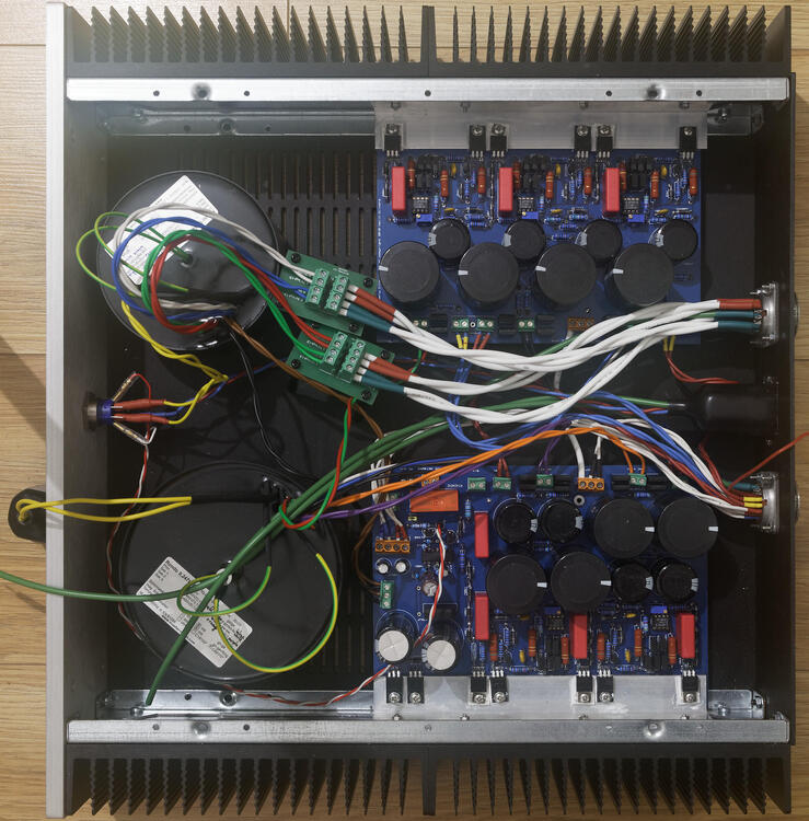
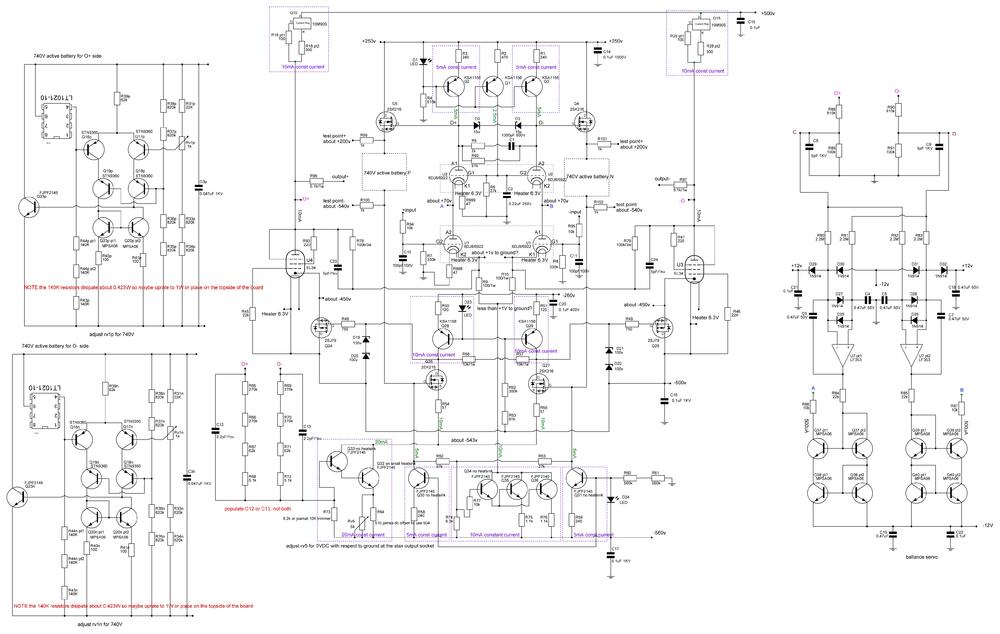
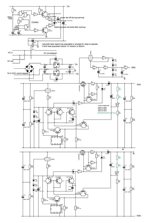
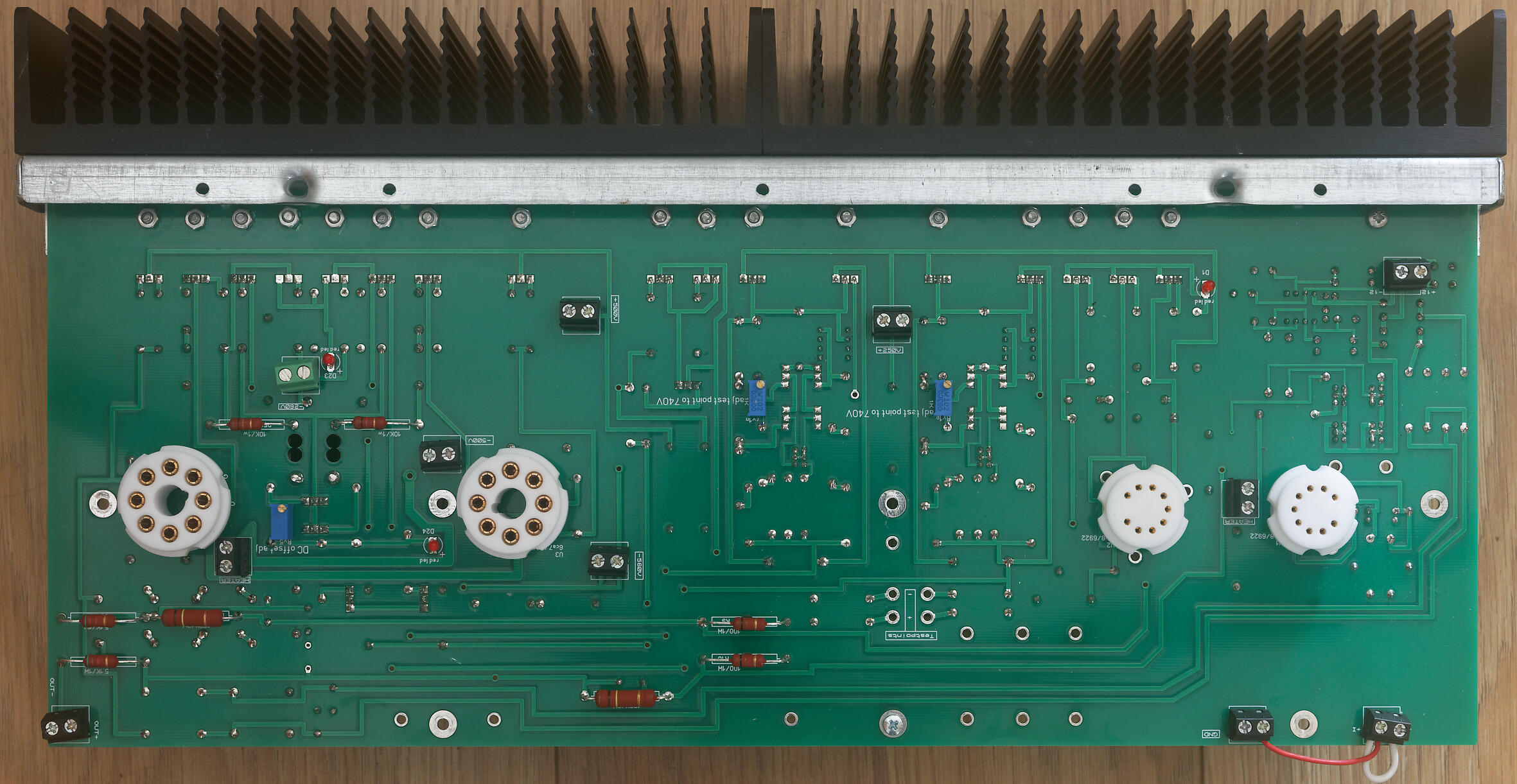
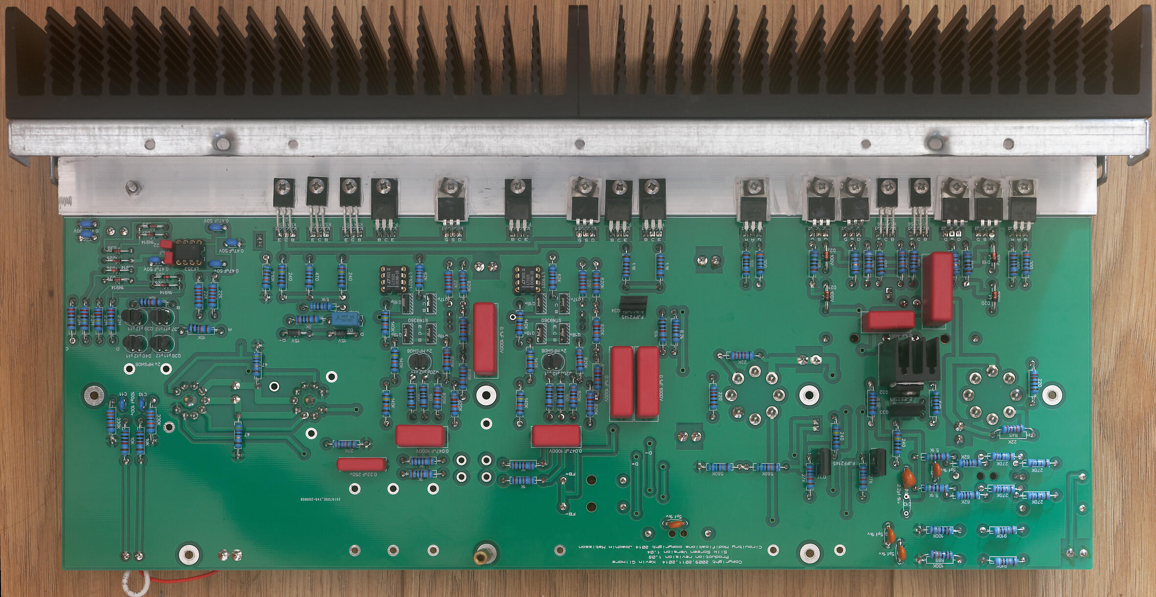
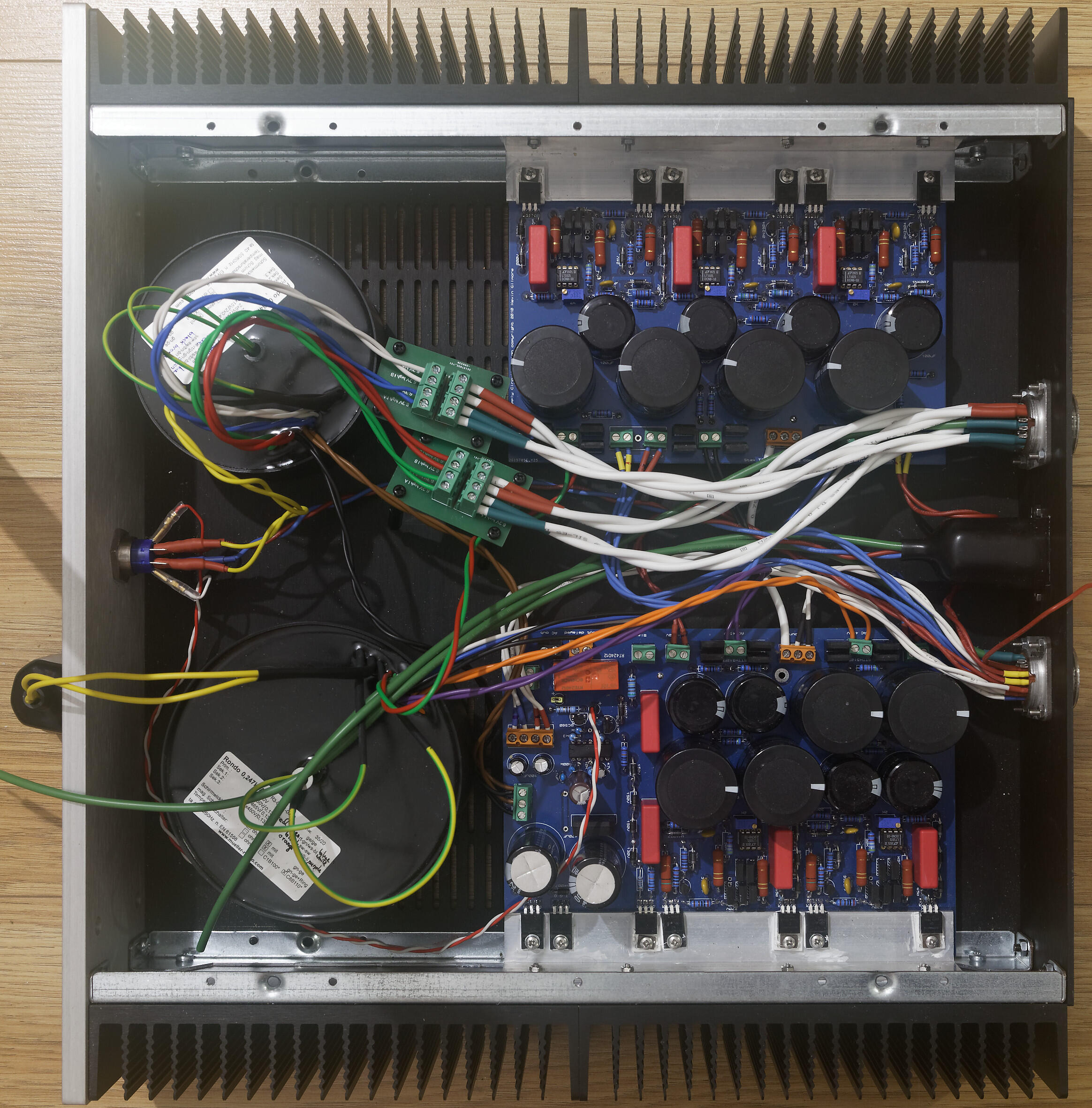
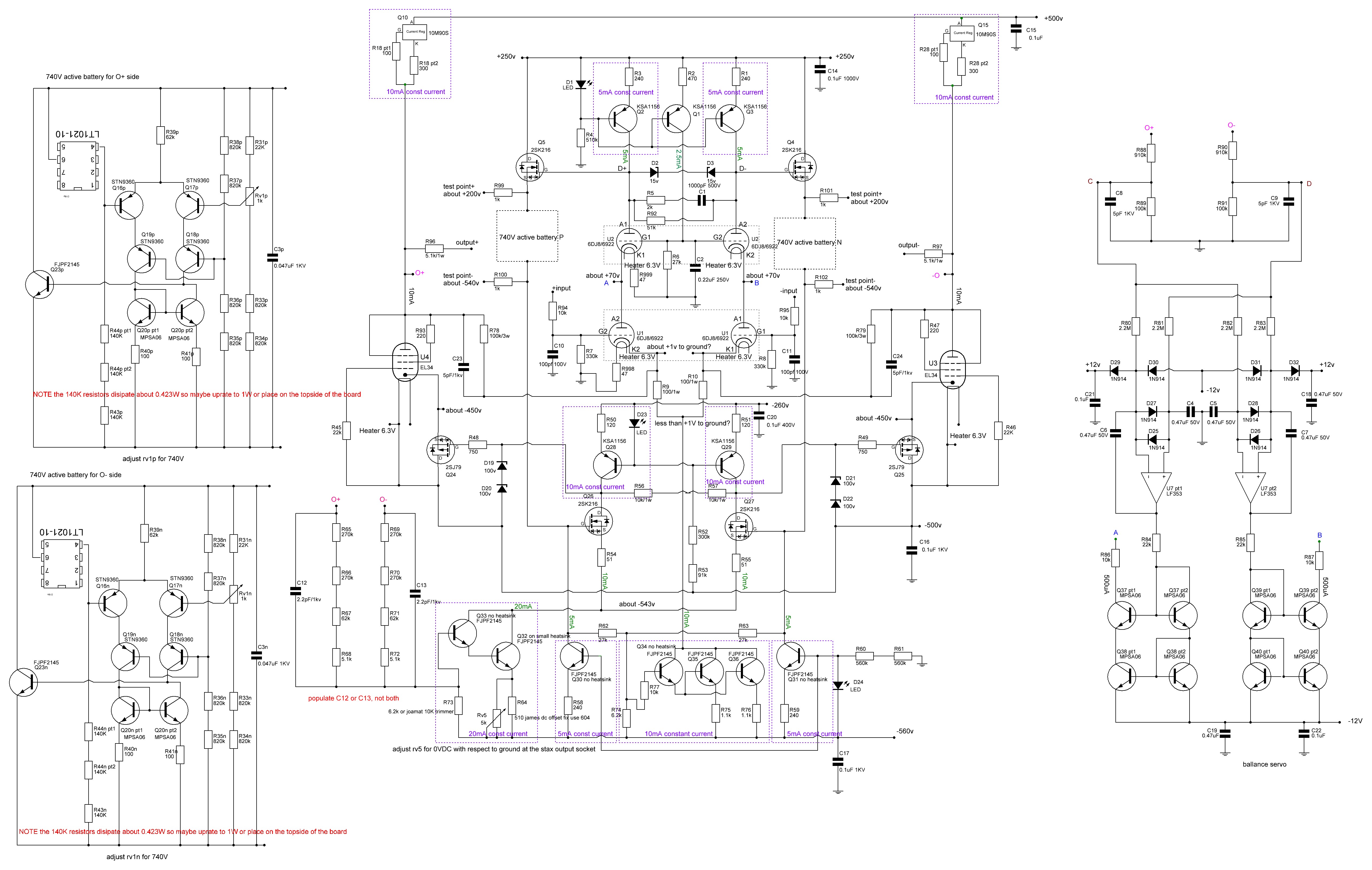
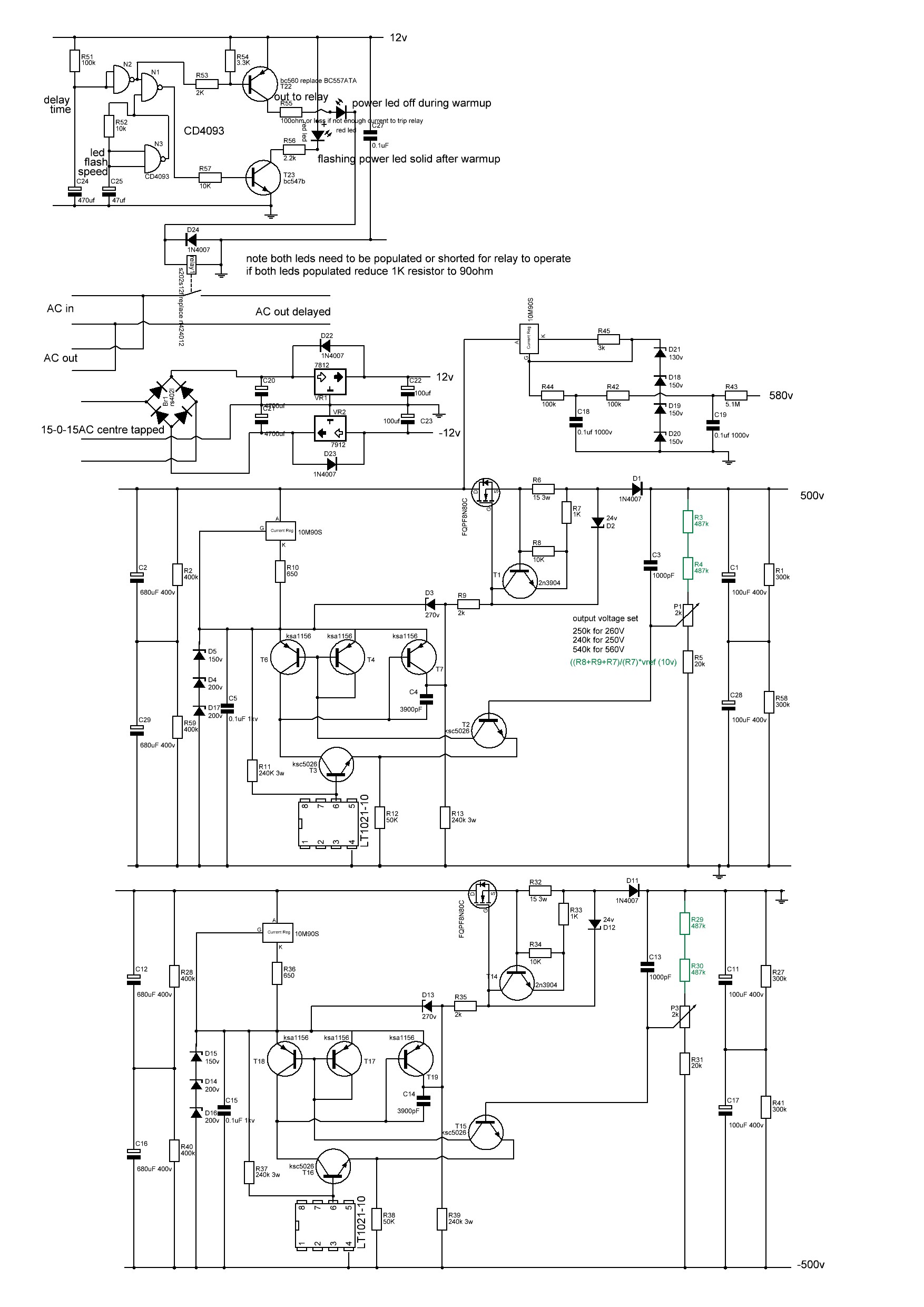
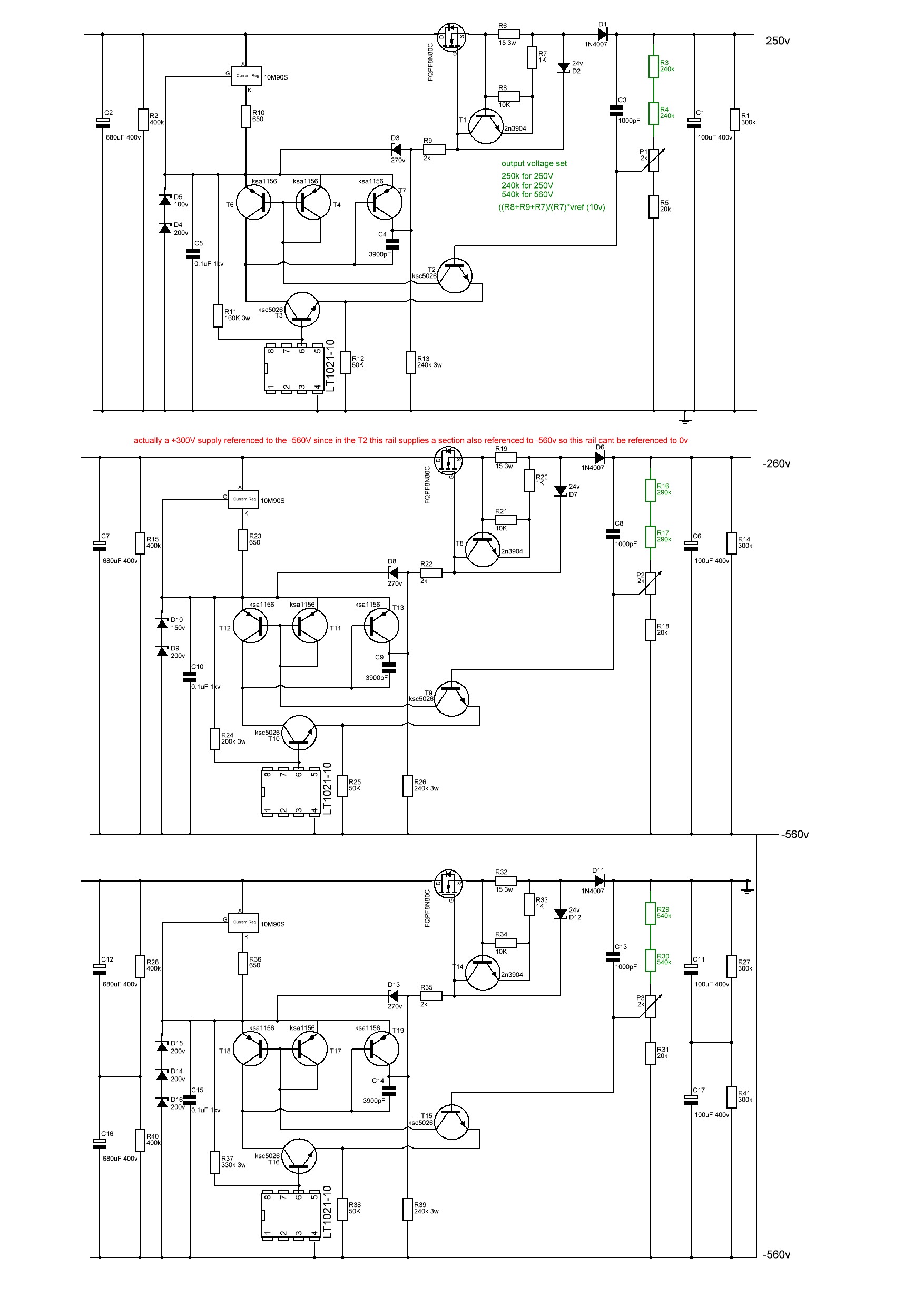
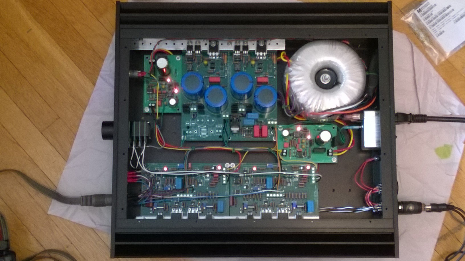
 1 point1 pointIt might be a little premature but I think I now have a working T2 using a modified version of joamat's staxt2nc3fdh7 amp files and kgsshv dc supplies.... Initial startup looks good. Channels started up seperately. Heater transformer running at full voltage. High voltage transformer on a variac. virtual batteries within 100mV of 740V before any adjustment. DC balance between + and - sides of a channel <1V without any adjustment, all 3 leds lit on both channels. once my hands stop shaking I will take a few photos... I have been dreading switch on... in the meantime here's a few build photos of a finished amp channel top and bottom, the amp and psu I modified the delay circuit on one of the psu boards to use a relay instead of the now unavailable solid state relay. I modified the amp boards so that 1. they fit into a 400mm deep chassis, hifi 2000 dissipante chassis. 2. they have screw terminals for all connectors on the top.. (less neat but easier for testing and rebuilding) 3. all resistors of 1W or more go on the top of the pcb with a drill hole under for increased airflow 4. groundpane is between 1.1mm and 1.3mm from any solder point 5. pcb is cut in half so each channel can be built, tested and mounted independently, 6. solder points for pot and input jacks removed and replaced with screw terminals. 7. silkscreen has instructions for adjustment of pots 8. mpsw06 transistors replaced with mpsa06 9. small standalone heatsink for Q34 FJPF2145 in the 20mA current source darlington pair has drill holes in the pcb by the fins for enhanced airflow. 10 all components have schematic numbers included in the silkscreen 11 leds and adjustment pots mounted on top side of pcb like the original T2 12 removed the bias input and 5.1M resistor (since the kgsshv psu already has the resistor in the bias section) I will be happy to release the gerber files of my modification once I am certain the amp is reliable For the build: wima film capacitors, mixture of koa cm1/2 and xicon 273 series 1/2W resistors, for higher wattage vishay pr02 and pr03 All resistors, diodes, zeners raised from the pcb. pcb 2mm with 2oz traces. All 1/2W resistors matched to 0.1% or better at 1khz on a good LCR meter between + and - sections of an amp board AND between left and right channels. all non psu and psu decoupling caps matched to better than 1% at 1KHz on a LCR meter between + and - sections of an amp channel AND between left and right channels. (except for the pF caps which are just too small to measure accurately). all leds and mpsa06 transistors matched on a dca75 curve tracer between + and - sections of an amp board AND between left and right channels. all zener diodes matched to within 1% or better between + and - sections of an amp board AND between left and right channels. separate umbilical cords for AC heater power and DC voltages all internal wiring 1KV silicon all signal wires will be cardas chassis wire volume pot tkd 2500 series left to do install rca signal wiring, volume pot and stax output socket test with signal generator and measure distortion etc collapse from T2 build anxiety drill top of case for valve sockets clean up wiring pray to the god(s) of electronics sort out grounds on psu post moar pictures Here is the schematic for the staxt2nc3fdh7 NOTE this is my reverse engineer based on the pcb and the original T2 schematic and has not been checked by anyone. ( as far as possible component labels reflect the original T2 component labels. In the case of 2 components replacing a single component in the original T2 the components are now labeled Xpt1 and Xp2. In the case of additional components no present in the original T2 they start with the number 9XX. In addition both batteries are shown and the the components labeled with a Xp for the O+ side battery and Xn for the O- side battery. Note the 140K resistors in the virtual batteries dissipate 0.423W each and I found xicon 1/2W 273 series discoloured and drifted by about 1% after about 6 months heavy use when placed on the underside of the pcb. So you may want to think about 1W resistors or place the resistor on the top side of the pcb. psu low voltage, bias, +500V -500V and hv delay reverse engineered from pcb and original schematic. not checked by anyone. psu +250V, -260V and -560V reverse engineered from original schematic and pcb not checked Note psu schematics changed 22/08/2022. Thank you to Rinat for spotting an error on the current path around the 3900pF cap.
 1 point1 pointTry those modern components and reduce high voltages to +/-400V (I’ve tried all except KSC1008 and J112). Old Modern 2SA1468 KSA1156 2SK216 KSC2690A 2SJ79 KSA1220A 2SC3381 KSC1008 2SK246 J112 2SK3675 FJPF2145 Mouser wants $51,51.1 point1 pointthermal grease lasts forever. I have a jar with original Newark part number on it, and its 50 years old. Still good. the stuff contains aluminum oxide or silicon oxide, or various other compounds in silicone and for voltages less than about 2.5kv its an insulator. Although it can have more capacitance than you might think.1 point1 point1 point1 pointJust adding yet another carbon build to the thread (crappy phone pics). 400v supplies rather than 450v allowed the caps to be board mounted in my chassis (though I am having some of Kevin's off-board PCBs made for a possible future 450v version). 400v also has the added benefit of running (slightly) cooler than the 450v version. Added the GRLV supplies but don't have a non-GRLV version to compare. But this amp is a true winner. Every time I listen to it I am awe struck at how good it is, particularly when compared to the T2 - they both have that ability to fool you into not realizing how loud you have cranked up the volume.
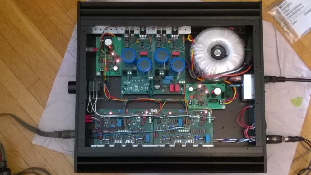
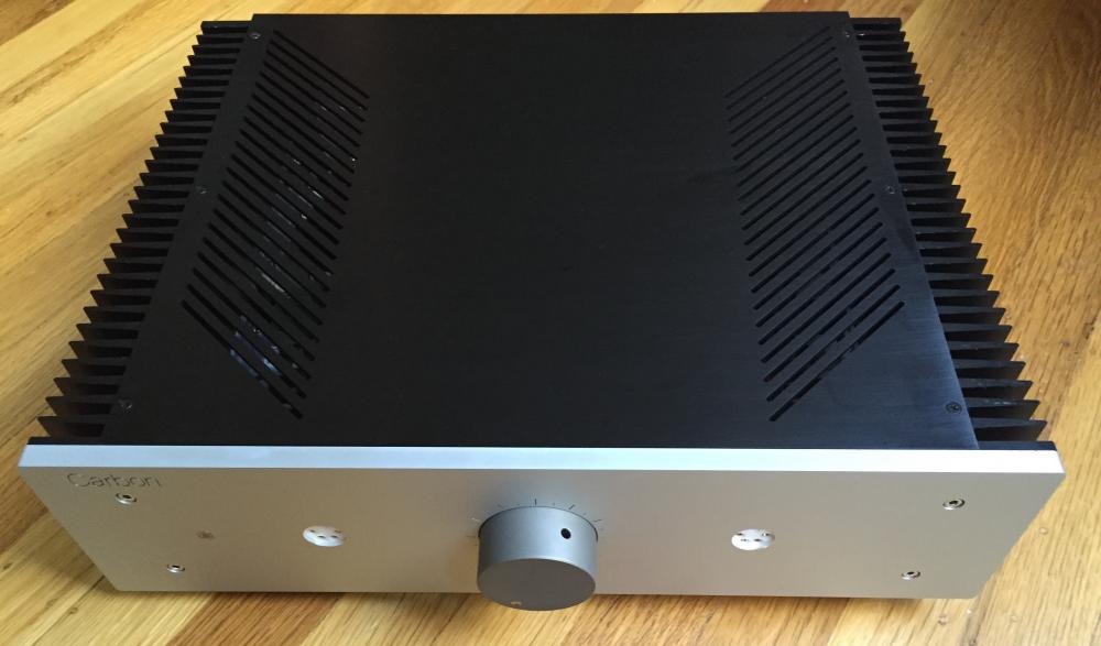
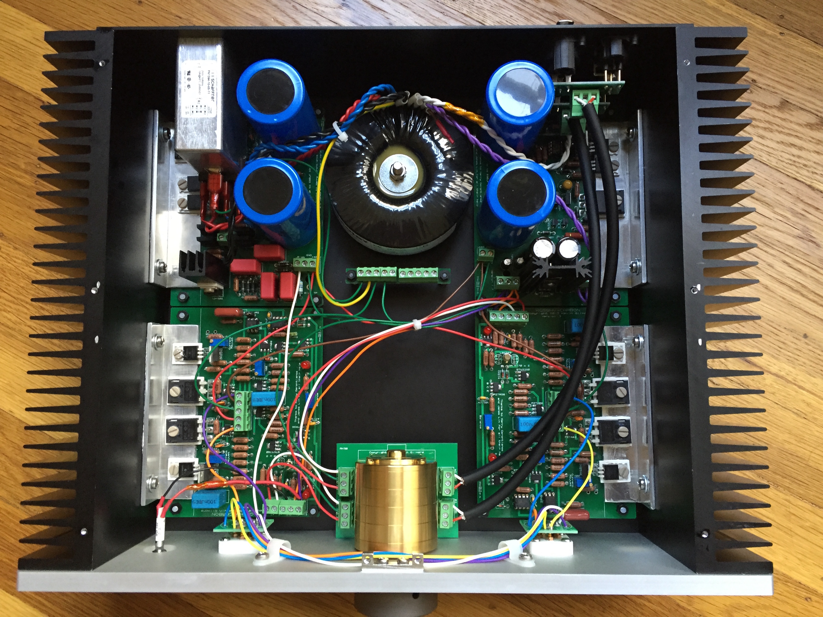
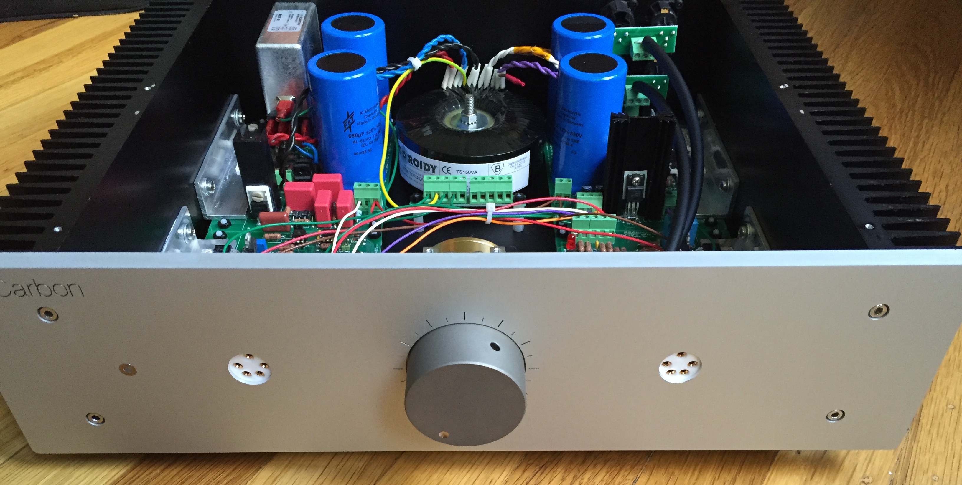
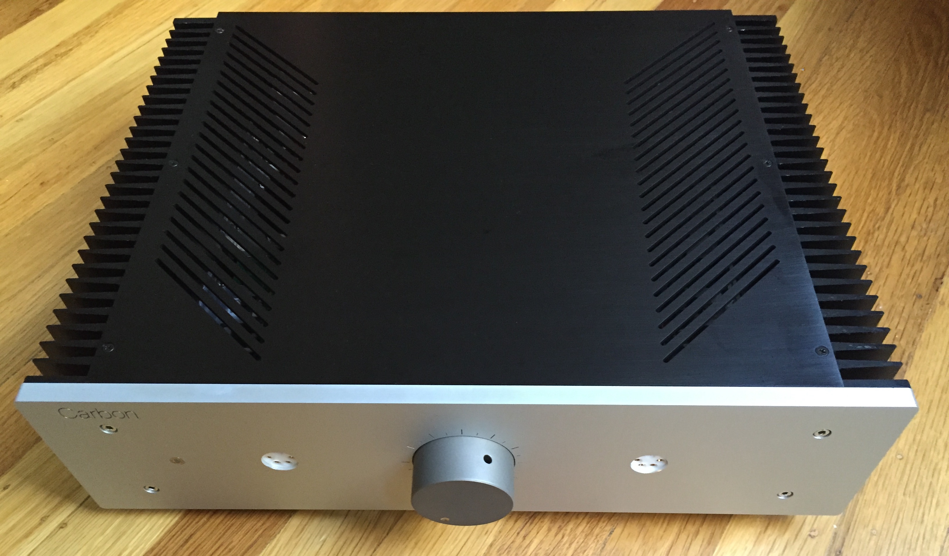
 1 point1 pointHere is my Carbon build. The layout is a lot like the KGSShv Cube I made in 2014 although this is bigger and easier to assemble. I have dubbed it the “Chunky”. I have two versions, a black/silver and an all silver and am building two of each. The Chunky measures 340 wide X 310 deep x 138 high, plus feet and weighs about 10 kg. As I wish to concentrate on other projects I do not intend to make more amplifiers for other people. I am intending to do a KGBH for myself. I have enjoyed the challenge over the last few years and have also met some great fellow head-cases. The KGSShv/KGST/Carbon KG designs I have built have all worked as intended and been easy to set up and all have given great musical pleasure. This is a sign of a great designer and I would like to note again my gratitude for the great gift given to this hobby by Kevin and Birgir, Kerry, Joamat, Jim L and all the others for their contributions and inspiration.1 point1 pointSweet. Thanks for the explanation about the voltage jump, guys! Pictures attached to this post. This was my first time working with external heatsinks. I underestimated the difficulty, and ruined one sink trying to hand-drill it. Total fail. Luckily, I discovered that a colleague owns a Tormach PCNC 1100, and he was kind enough to invite me to his workshop and let me use the machine. A gorgeous device, let me tell you. It made short work of all the drilling. Then I hand-tapped all the holes (I think the Tormach machine can tap holes, but I wasn't sure how to keep the oil flowing and the taps clear of gunk for this operation). The heatsinks themselves took some finding. They are Fischers, 10mm high by 300mm long, with 40mm fins, part SK 56 100 SA. High quality, and hard to find in the US. With 10mm standoffs, the entire amp fits nicely into an enclosure just slightly larger than 2.5U. (I also tried sinks with identical dimensions from HS Marston, and they sucked: all extrusions I received were crooked, and there was no way I could have bolted angle brackets to them.) The rest of the chassis was done by FPE. In retrospect, I wish I extended the top and bottom panels to overlap the sharp edges of the heatsink fins, with large rectangular cutouts so air could still circulate. Still, I'm happy with how the case turned out. If anyone cares, I'm happy to share the .fpd files. Because FPE does not do anodizing, I had to have the panels made in two steps: one run before getting the pieces to an anodizer, and one run after. The circuit itself was easy to assemble and adjust. No trouble from the Toroidy transformer. Overall, the amp runs a little warm to the touch (at 20mA output): cooler than either my KGST or mini-KGSSHV, though we'll see how it fares after more than an hour (all I've listened so far). Many thanks to @mwl168 for the group buys and build notes, @sorenb and @jdineshk for the capacitor group buy and help, @vilts for making the spectacular titanium knob, everyone else who answered questions and provided inspiration, and many many thanks to Birgir and Kevin for making all this possible in the first place.
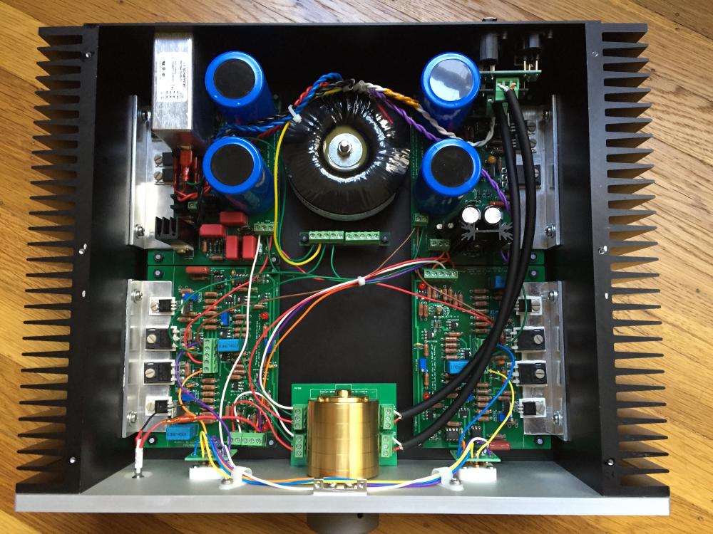

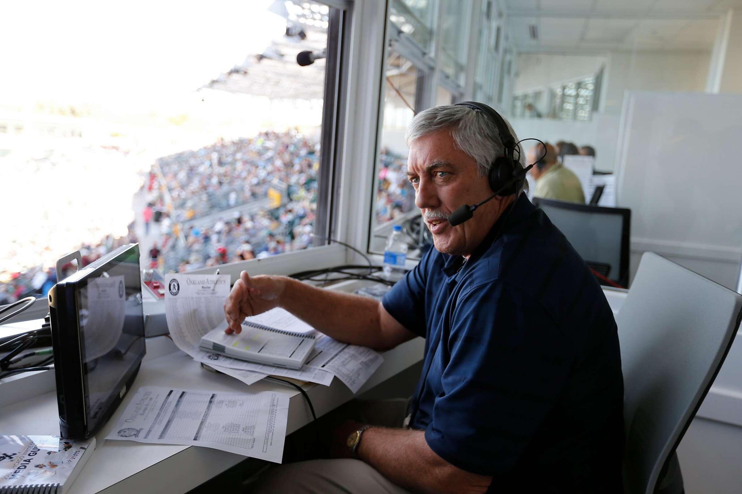
 1 point0 pointsRIP Ray Fosse, Oakland A’s longtime broadcaster and former MLB Catcher. Ray’s broadcasts taught me to love the game. His understated dignity and professionalism was something I’ve always admired. He was always a very stark contrast with the Giants broadcasters across the bay. I still don’t forgive Pete Rose for nearly ending Ray’s career in a violent collision at home plate durning an all-star game that didn’t even count. https://www.sfgate.com/athletics/article/Ray-Fosse-former-A-s-player-TV-commentator-dies-16531377.php
 0 points


Important Information
By using this site, you agree to our Terms of Use.
Account
Navigation
Search
Configure browser push notifications
Chrome (Android)
- Tap the lock icon next to the address bar.
- Tap Permissions → Notifications.
- Adjust your preference.
Chrome (Desktop)
- Click the padlock icon in the address bar.
- Select Site settings.
- Find Notifications and adjust your preference.
Safari (iOS 16.4+)
- Ensure the site is installed via Add to Home Screen.
- Open Settings App → Notifications.
- Find your app name and adjust your preference.
Safari (macOS)
- Go to Safari → Preferences.
- Click the Websites tab.
- Select Notifications in the sidebar.
- Find this website and adjust your preference.
Edge (Android)
- Tap the lock icon next to the address bar.
- Tap Permissions.
- Find Notifications and adjust your preference.
Edge (Desktop)
- Click the padlock icon in the address bar.
- Click Permissions for this site.
- Find Notifications and adjust your preference.
Firefox (Android)
- Go to Settings → Site permissions.
- Tap Notifications.
- Find this site in the list and adjust your preference.
Firefox (Desktop)
- Open Firefox Settings.
- Search for Notifications.
- Find this site in the list and adjust your preference.