Leaderboard


Popular Content
Showing content with the highest reputation on 02/22/22 in Posts
-
10 pointsI’m going to post this in its own thread as so many people are asking me for X9000 impressions, and it makes sense to have them somewhere where they are easy to find. I was also going to take some pictures to add to this review but I’m just wiped. Might add some later if these ever present storms let up for some good light. I’ve now had the SR-X9000 here for over a week so time for a writeup... as my email inbox is full of people asking for just that. 🙂 First impressions were very promising, the build quality is superb, and those drivers are just a marvel to behold. I do like the new replaceable cables even, though it is a bit of a copy of the King Sound setup, and they really should include a 2.5m cable and a 5m one, the 1.5m makes no sense to me. The earpads might be a tad too big in terms of open area for their own good but they are well made and comfy. That new arc design is also excellent, far better than the 009 mess. The inspiration from the SR-Omega is clear but the build quality here is far, far better. Same loose feeling fit too; they mostly just hang off the head with minimal clamping. I really like how they drew inspiration from them, but I also have some issues with how that was executed… more about that later. The system I’ve been using them in is my main rig, Denafrips Terminator DAC feeding a Carbon CC all being fed from my main PC. Now for the sound, these are clearly voiced in the same direction as the 009/009S but not as horribly colored as those two. They sound open and lively with decent bass and the forward slant is there but far better than the predecessors. I remember thinking… “these are what the 009’s should have been 11 years ago” so yeah, not bad at all. For some recordings they really work but yeah… a few tracks in and the cracks began to show. A bit of a backstory, I’ve likened buying Stax to being in an “abusive relationship” for the last 15 years. Back in 2007 they brought us the 007Mk2’s with all of their issues. Sure, they could be fixed easily enough with some blutac but yeah it was a sign of things to come. At CanJam it was confirmed there was a new version of the 007Mk2’s out and they were even worse (the Mk2.5 as we called them), the blutac helped but could not fix the terrible voicing. Then it was announced a new flagship was incoming and the SR-009 landed in 2011. Now we all remember the clusterfuck that was, drivers failing left and right and forward sound with pitiful bass response… yeah, I’m not a fan. One bright spark was in 2014 when I got a new set of 007Mk2’s and they had clearly been changed for the better. The port finally kind of worked and the voicing was more like the Mk1’s. Then we got the limited edition 009BK (2016?) which I found to be a small improvement over the 009 but still that same sound and finally the 009S is 2018. Less said about them the better, quickest I’ve ever sold one of my flagship phones there… That brings us to the present and since the wait for the SR-X9000 was so long, I had time to bolster my collection to compare against them. I got a used set of 009S just to make sure I didn’t like them (that was still the case), a Voce (not arrived yet due to some shipping snafu’s) and finally the one I really wanted, a SR-Omega with early 007 Mk1 drivers. I had a set a decade or so ago and it’s really the only set of headphones I truly regret selling. I also got my final set of Audeze CRBN’s to compare against the new kid on the block. I had a lot of fun doing so and after a few hours I gravitated to a direct A-B test of the SR-Omega/007 against the X9000. Makes sense as they are a similar idea, put a more modern driver into that same basic housing design. That did reveal the two main issues with the X9000’s, the bright edge to everything which is just borderline annoying and more distracting than anything. Second are the imaging issues… First off, the brightness, with the 009’s they were really intolerable, and I’ve never been able to just sit down and enjoy a listening session with 009’s. It’s not that bad here but it’s always present. Some tracks it just blends in and becomes part of the sound while on others it stands out and takes away from the immersion. What makes it worse is that there is no logic to which tracks have that edge to them, bright ones which I would expect to have it… well it just blends in while darker ones have it. Must be a resonance issue as there is so little damping here. Now with the imaging, I think Stax made a mistake having the outside screen angled like that. On the SR-Omega it is perfectly parallel with the drivers but on the X9K, it is maybe 3mm further out towards the front. This or some part of the driver structure might be the culprit for the odd imaging. Let me clarify, they throw a large soundstage but it’s very much a “three blob affair”. Nothing wrong with that really but it’s the front imaging which sounds off for me. It’s all a bit to distant and boxed in while not being as focused as the 007 soundstage. When you pick up on it, it becomes very apparent and distracting. As comparison, let’s take the SR-Omega and SR-007Mk2. The SR-Omega throws a wide soundstage but it’s all a bit loose and diffused. Now the 007’s (all of them really) have a much tighter, more focused soundstage which also does something unique, there are layers to it. With the SR-X9000 it’s more like the SR-Omega (which makes sense) but more localized to the three blobs and the middle one has that odd boxed in effect while being a bit distant. Now other than these two things, these are well made and high performing sets, but these two things annoy me enough for them to not make my top/best ever list. The SR-007’s are more laid back and “darker” but also more neutral and truer to the original sound. The SR-Omega/007 is a more fun and looser version of that sound but those slight deficiencies just make them a welcome change, doesn’t make them any less neutral. They simply act as a bridge bringing those two sounds together, absolute purity of the 007 with the more warm and loose nature of the SR-Omega. I feel I should also talk a bit about the new kid on the block, the Audeze CRBN. Now I’ve had a few of them here, prototype units to the final production version and it really is the antithesis of the SR-X9000 is terms of fit and sound. The CRBN is snug as it hugs your head with thick and supple earpads. The sound is far more damped so it is darker but still very open and expansive. Now they aren’t perfect, they have that slight issue with the midrange presence due to the heavy damping, but it is minor overall. They are really what the HE90 could have been back in the day, more diffused than the 007’s but with proper bass. Nice way to tie back the 007's were always being compared to the HE90 back in the day. Lastly, how are they to drive. Well… as one would expect with a driver this size, they need a lot of power to behave. That brightness will quickly get out of control, especially at higher volume levels when the headphones don’t have enough power behind them. I’ve only tried them on a couple of amps so far so I’ll need more time with that, but I’d say powerful and neutral amps will suit these just fine. Conclusion/TL; DR These are good but not as good as they could have been. They are too forward sounding though not as bad as the SR-009, 009BK or 009S. I crave neutrality over everything else, the headphones should just present the sound with as little an impact on it as is possible. If they fail to represent a part of the spectrum, that’s fine but if they add something… then I have a problem with it. The brightness and imaging issue does disqualify them due to that, but I will keep them around, nonetheless. With some material they work well and plus I’m in a collecting mood… 😉 I'll probably add to review later on as I spend some more time with them. Finally, I’m going to be a bit cynical and think Stax are doing this sound signature on purpose and not for the obvious reasons. This is exactly the type of sound which grabs you on a quick audition or impresses the useless audio reviewers out there who don’t know any better. Back in 2002 the 007’s got no love at all as they are the definition of “unimpressive at first audition”, let along not many amps around at that time which could drive them. Stax are clearly now trying to make money and not audio purist just trying to make the best product possible, nothing wrong with that, so I’m glad this wasn’t a complete hack job like the 009S.10 points
-
5 points
-
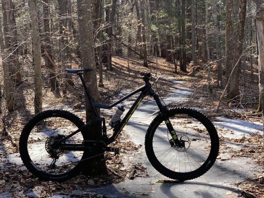
3 pointsIt hit 50 today and with the full-squish back from repairs I decided once more, into the woods, was required. Studded tires were a must, with mixed conditions of glare ice and then surface mud. Huge fun.
 3 points
 -
2 pointsHey! I know that guy! Video is time-stamped. Congrats, Kerry, and good luck at the show!2 points
-
2 points
-
I like Bitwarden. Fully-featured free version, with very cheap premium option.2 points
-
TL;DW: Would anyone like to buy a Synology NAS?2 points
-
2 pointsGlad you liked it, the look is great. That's one of those simple things to cook that are very enjoyable.2 points
-
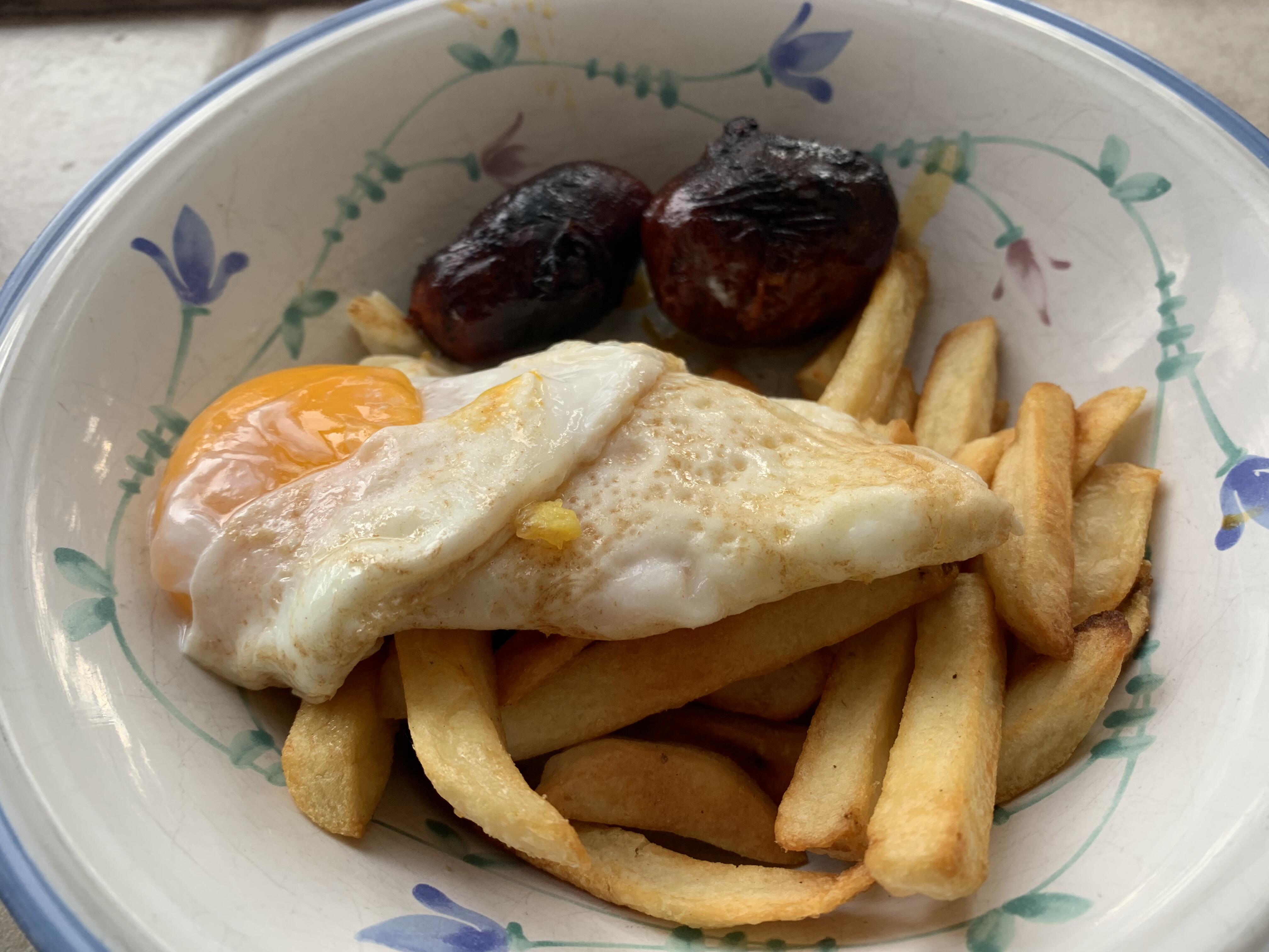
2 pointsMy take on Spanish style huevos con chorizo with Central American chorizo while in Tahoe for ski week. My eggs slipped before my photo opportunity but the flavor was great and the papas fritas were a big hit. Thanks for the inspiration Antonio and Steve.
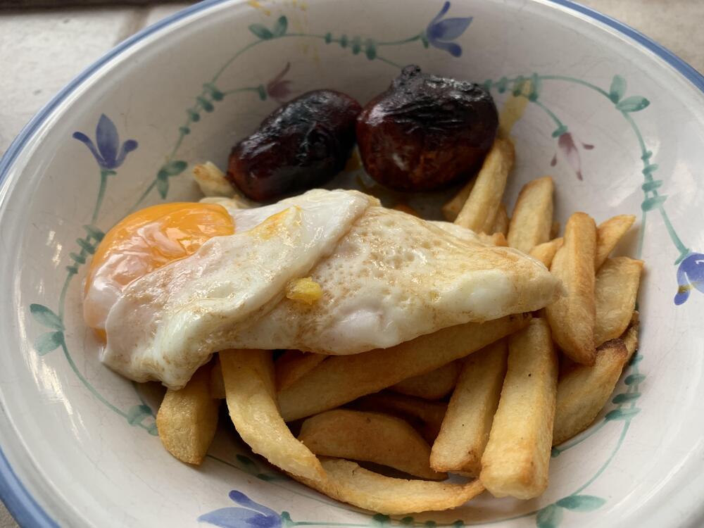 2 points
 -
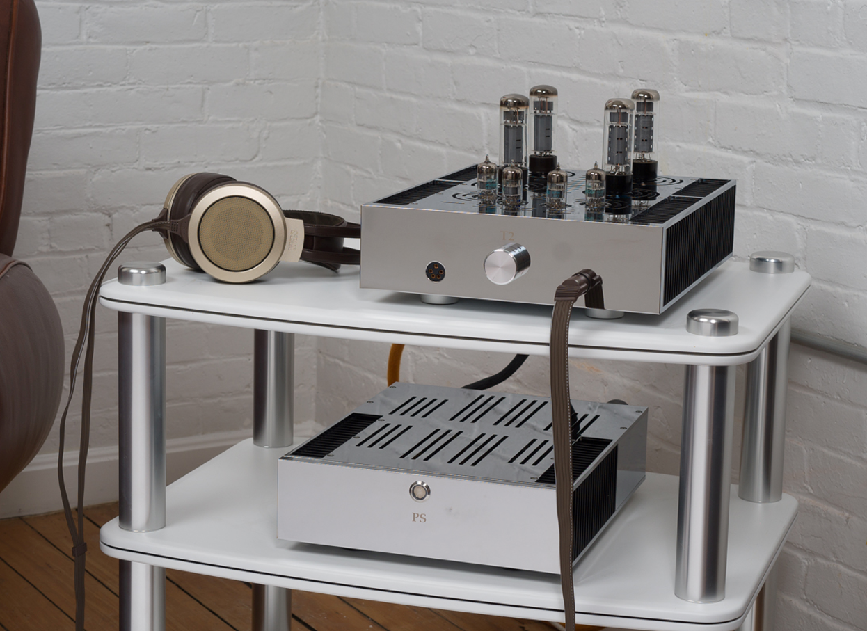
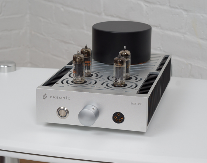
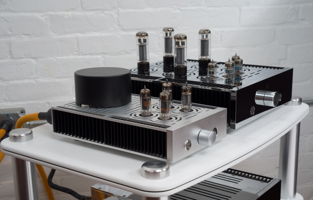
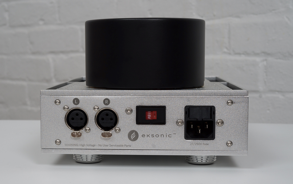
1 pointWe’re launching a new company – Eksonic – along with our new amplifier called Aeras. Launching an audio company is something I’ve had in the back of my head for many years and I’m proud to be able to bring a passion to market. I've been building my own version of the DIY T2 for quite some time now and have long hoped to capture the spirit of the beast in a smaller single chassis design that's more accessible to many. We think we've accomplished that with the Aeras. Aeras is the result of endless hours of circuit design and analysis, brainstorming and many iterations of prototyping and testing. Our initial users have had great things to say about this new amp. We’re going to be launching the company formally at the NYC CanJam later this month. We’ll bring our DIY T2 along with the Aeras so people can hear them side by side. I hope to see some of you at the launch

 1 point
 -
1 point
-
1 point
-
1 point
-
normal Dragonfly prices are brutal and i wouldn't be a buyer... Similar to Bird Rock and Paradise. they recently did a big clearance and i grabbed the Elida Estate green tip at almost half off and it's much closer to worth it. not sure if those sales are normal or if i was lucky. Hatch is awesome and i would recommend. i had their advent calendar last year and it's the best run of coffee I've ever done. also their relationship with Finca El Paraiso seems incredibly unique and gives them access to stuff i haven't seen elsewhere. Paraiso is a ridiculously good farm, probably in my top two. (i should note i only do pour over. no espresso)1 point
-
1 pointI'm just reading Mark Cavendish's book Tour de Force about his record winning Tour de France last year, when he matched Eddy Merckx's sprint record of 34 stage wins. Cav was 35. It is a must read for anyone interested in pro cycling, and really communicates the sheer brutality of the sport. He said that splits happen coming over the top of a climb. Lead riders go over the top pushing 400W, but get a bit of slipstreaming from the camera motorbike. The next group don't have that and have to push 440W. An individual doesn't get a group effect and has to push 480W - and, he says, that is why splits happen. In a sprint, riders - including Cav - can push up to 2,000W for a number of seconds. After 4 or 5 hours in the saddle. It is also perfectly clear he doesn't like Sagan one tiny bit. Looking at the web, he's still competing age 36, will be doing the Tour of Britain, and probably another Tour de France to try and beat Merckx's sprint record.1 point
-
1 pointVisited some friends in the fine city of Gloucester (GLOAHstuh). It's a wonderful fishing port that's being (not so) slowly gentrified to the moon. While there I picked up a shiny new MacBook Pro (yay!), a new iPhone (double yay, my old one was nearly dead), got my vacc booster, and got a bottle of Georgian (as in the country) catsup as a gift. Weirdly, getting my vax boster shot proved to be a PITA. The first THREE places I called said "yeah, we don't do that anymore." As best I can figure, most of the country is already boosted and the remaining population mostly consists of pants-on-head retard anti-vaxxers "the vaccine-hesitant." ADD fucks who are a day late and a dollar short but not Flat Earth Society antivax like myself are a rare breed. In any case, I got my jab and my arm hurts like hell.1 point
-
1 pointMy landlord Dave's wife is in Hawaii, so the permanent and the temporary batchelors are having Migas for breakfast. Corn tortillas cut into strips and crisped in a bit of oil. Scallions and Orange bell pepper sauted with a little scorch. Tomatoes and avocado, chorizo and of course eggs.
 1 point
 -
1 pointChorizo in Spain is a grocery product, a kind of sausage with the stuffing into guts, made with pork meat and fat somewhat marinated with lots of paprika, hence the red color. Some types must be cooked, so you eat them with eggs, potatoes into a garbanzo or bean stew, with migas... but other types are cured and are eaten like ham or salami. In most South America countries they call chorizo to very different things, in some countries it's a kind of sausage but different to the Spanish type, or even a minced meat cured or marinated. Either way it's usually delicious1 point
-
1 pointPut a brisket on at 8am, just pulled the last piece off at 5:30. I cut it into three sections based on thickness to see if I could time things better than just running the whole thing until the thickest part was done. Homemade mac and cheese is in the oven, slaw is curing in the fridge, dinner should be alright.1 point
-
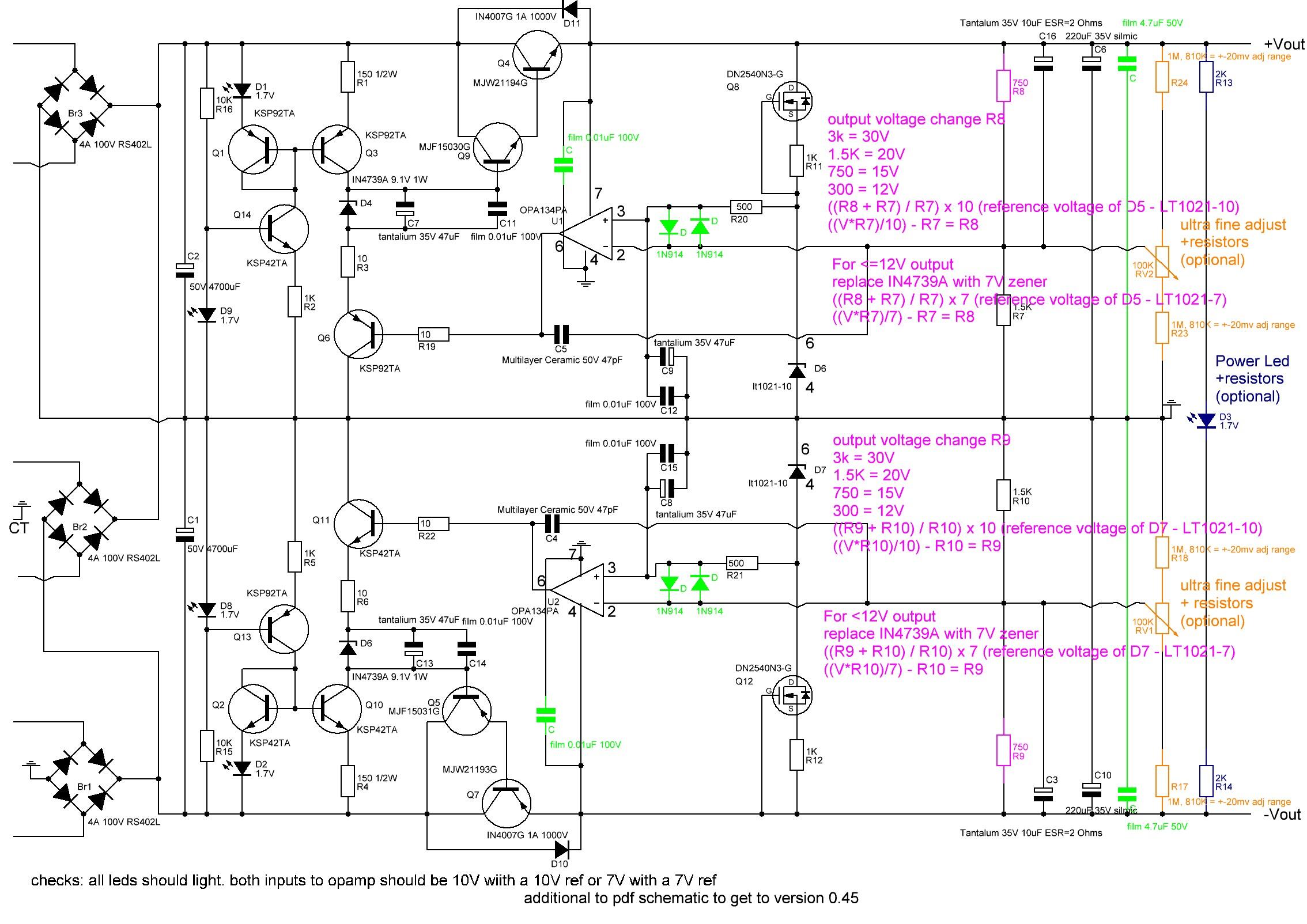
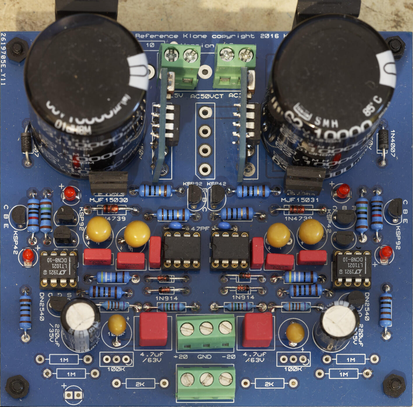
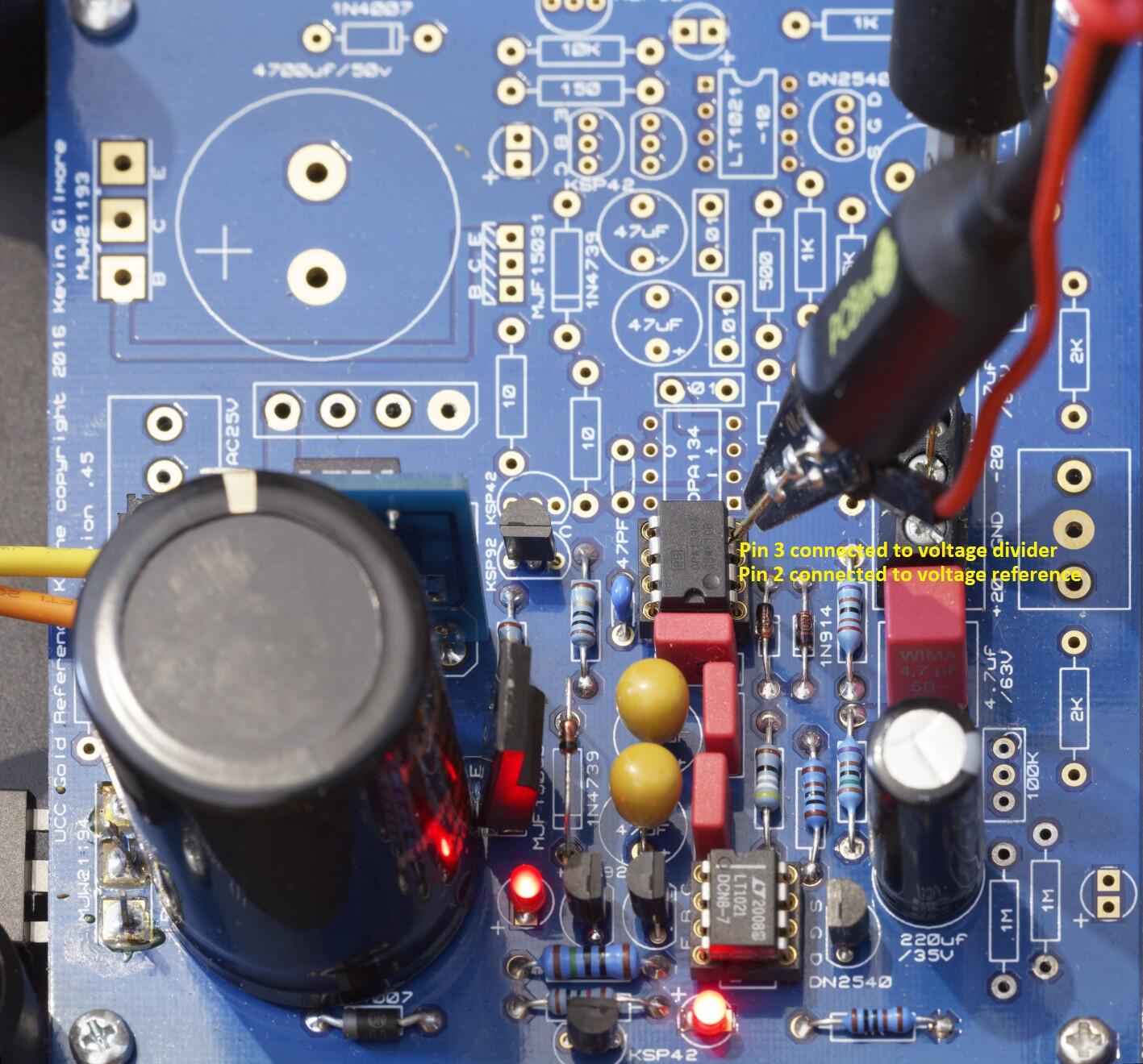
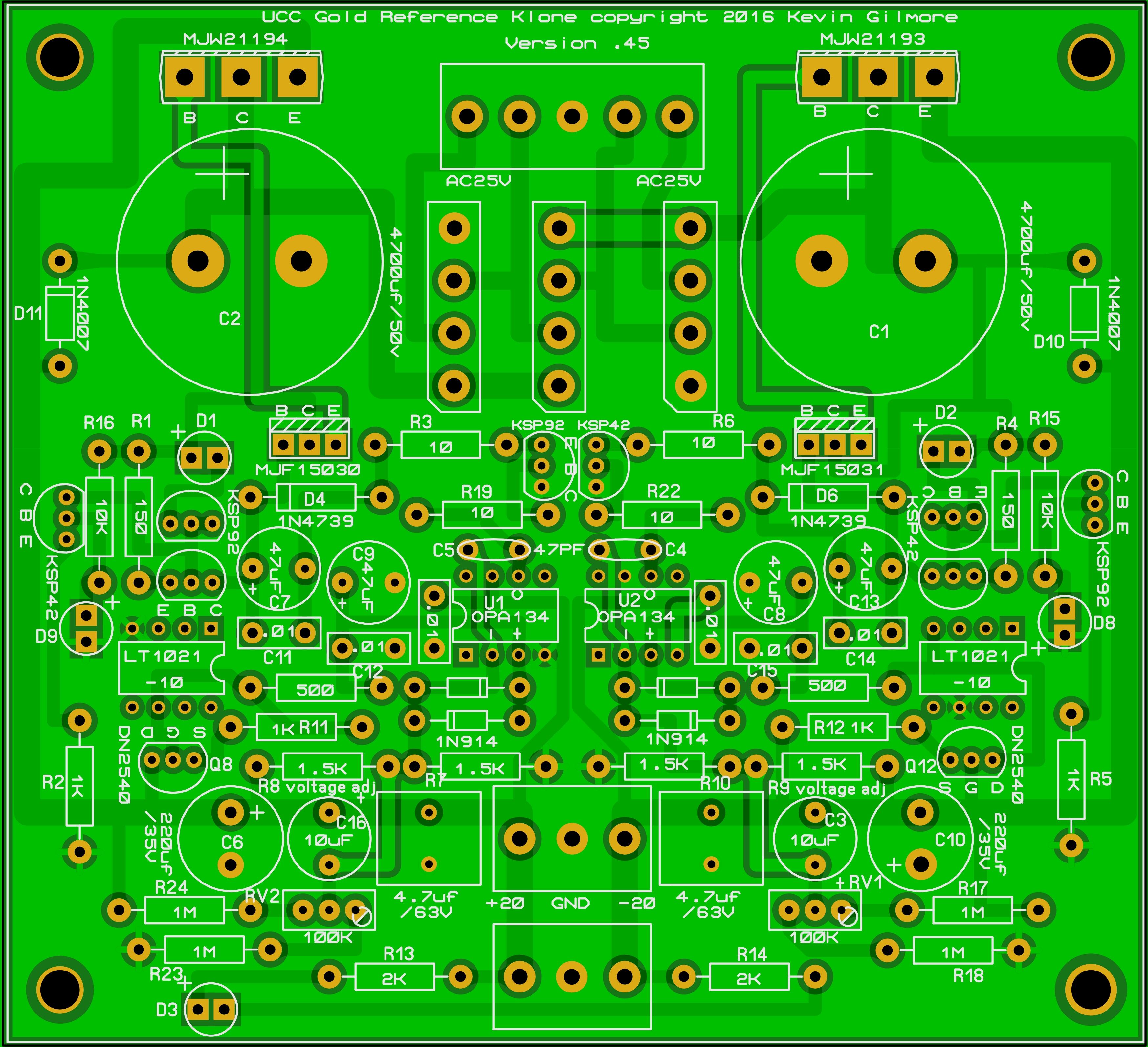
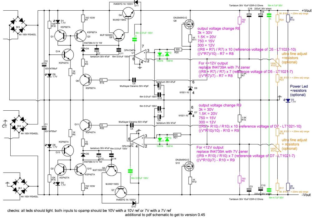
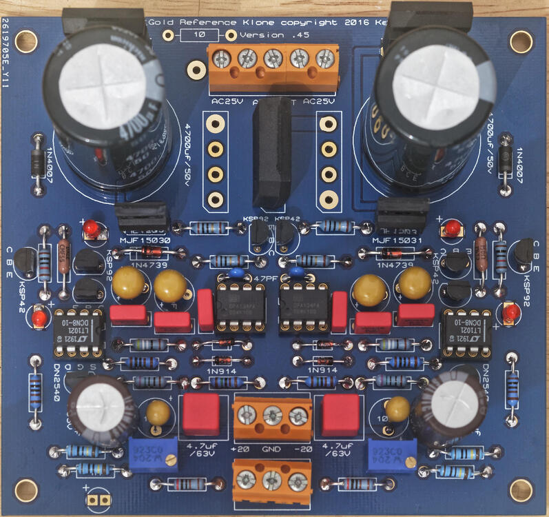
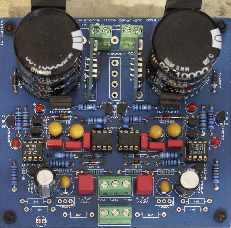
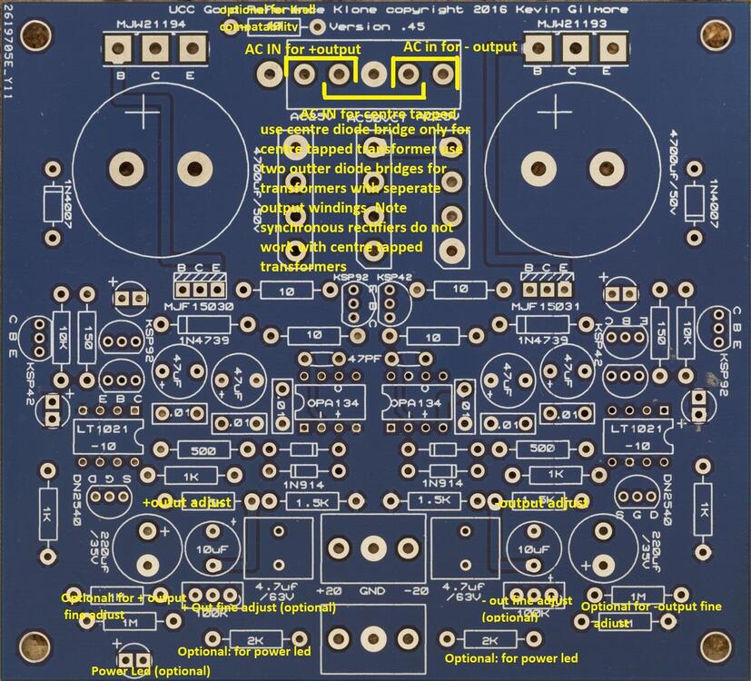
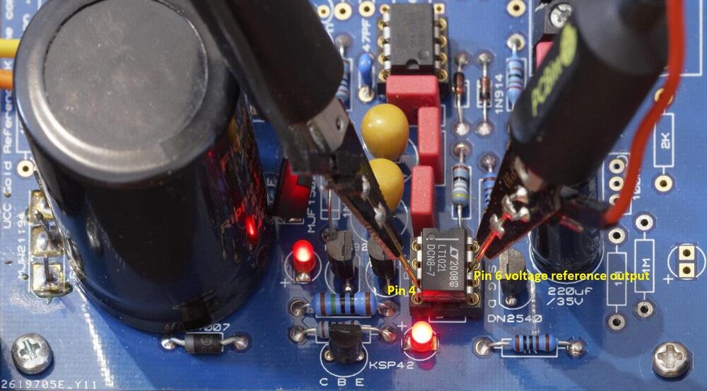
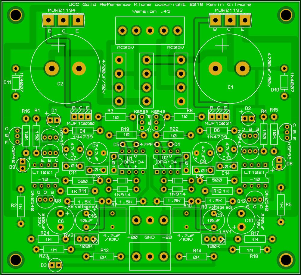
Golden Reference LV Build Guide Schematic for the golden reference LV: parts in green are new additions compared to the published schematic pdf in joamats post above. Parts in purple set the output voltage, parts in brown are the optional fine output adjust and parts in dark blue are the optional power led. Component Layout Optional parts and Options: 1. if you don't want to have a power led fed from the LV board omit the 2K resistors R13, R14 and the led D3 2. if you don't want very fine adjustment of the output voltage omit the 1M resistors R17, R18, R23, R24 and the trimmers RV2 and RV1. If you want more adjustment range reduce the value of the resistors. With 1M ohm resistors the fine adjust can only change the output voltage by a few mV. Replacing with 810K resistors provides a little more adjustment range ~ 20mV but at the expense of decreasing the temperature stability. A cheaper alternative for good output accuracy is to use 1/4W 0.1% low ppm e.g. 15ppm resistors for the voltage set resistors and omit the fine adjust completely - which is cheaper and improves the temperature stability. 3. if you have the dual output board (which has both positive and negative output rails) either you populate the middle diode bridge only and use a transformer which is centre tapped OR you populate the two outer diode bridges and use a transformer with two separate output windings. If use use synchronous rectifiers instead of diode bridges use must use the second option and use separate windings for positive and negative rails. Do not populate all three bridges. If you use a centre tapped transformer you must connect the centre tap to the middle screw terminal (which is connected to the GRLV ground plane) of the 5 terminal AC input block . Do not use a synchronous rectifier to the centre bridge it will not work correctly and can result in the driver mosfets of the synchronous rectifier burning. Note the GRLV cant output less than the voltage of the voltage reference (LT1021), ideally for proper regulation the output needs to be more than about 2V higher than the LT voltage reference. So for about 12V or less output it is recommended you change the 10V reference for a 7V and the zener diodes for a 7V. For 12V output 10V reference or 7V reference can be used but the 7V reference version may have less noise. Maximum output is constrained by the voltage rating of the caps and is about 30V without modifications. Setting the Output Voltage For the positive output R8 and R7 control the output voltage along with the voltage reference, the output voltage is ((R7+R8)/R7)*voltage reference output D5. Assuming you keep R7 at the stock value of 1.5K: output voltage change R8 to 3k = 30V 1.5K = 20V 750 = 15V 300 = 12V In general to calculate R8: ((Voltage required * R7)/voltage reference D5 output) - R7 = R8 For the negative output R10 and R9 control the output voltage along with the voltage reference, the output voltage is ((R10+R9)/R9)*voltage reference output D7. Assuming you keep R10 at the stock value of 1.5K: output voltage change R9 to 3k = 30V 1.5K = 20V 750 = 15V 300 = 12V In general to calculate R9: ((Voltage required * R10)/voltage reference D7 output) - R10 = R9 Photos of finished boards for reference: This version uses a single diode bridge so this is setup for a centre tapped transformer, also has the trimmers and resistors for the power led populated but no power led installed. The build uses 4700uF reservoir caps and silmic 220uf output caps and 1/4w resistors from vishay and dale. This is what you get using the BOM link in this post (see bellow) and is very close to the original BOM published near the beginning of this thread. This version is setup for dual separate transformer windings, and has no power led or trimmers implemented. It also uses synchronous rectifiers instead of diode bridges, nippon chemicon 10000uF reservoir caps, Panasonic FR series 220uF caps and 1/2W 50ppm 1% koa resistors. The resistors that set the output voltage are 1/4W TE 0.1% 15ppm for increased temperature stability and output accuracy. This is my current default build. BOM (based on 10V voltage reference and all options being populated) https://www.mouser.com/ProjectManager/ProjectDetail.aspx?AccessID=edda1bdbf7 Component list with cap size information Br1,Br2,Br3 = 2 x 4A 100V RS402L use 2 for dual winding transformer use 1 for centre tapped transformer C,C = 2 x film 4.7uF 50V 5mm lead spacing 0.5mm lead diameter C,C,C11,C12,C14,C15 = 6 x film 0.01uF 100V 5mm lead spacing max size ~ 7.6mmx3mm 0.5mm lead diameter C1,C2 = 2 x 50V 4700uF 10mm lead spacing max diameter 25mm, 22mm more comfortable fit main reservoir cap I also use Nippon Chemicon 63V 10000uF which just fit. C3,C16 = 2 x Tantalum 35V 10uF ESR=2 Ohms 5mm lead spacing 0.5mm lead diameter C4,C5 = 2 x Multilayer Ceramic 50V 47pF 5mm lead spacing 0.5mm lead diameter C6,C10 = 2 x 220uF 35V silmic or Panasonic FR series 5mm lead spacing 12.5mm max diameter C7,C8,C9,C13 = 4 x tantalium 35V 47uF ESR=0.8ohms 5mm lead spacing 0.5mm lead diameter D,D,D,D = 4 x 1N914 D1,D2,D3,D8,D9 = 5 x 1.7V red led 4 are required one is for optional power led leally all 4 main leds should be from the same batch and have similar characteristics. D10,D11 = 2 x IN4007G 1A 1000V D4,D6 = 2 x IN4739A 9.1V 1W use 7V zener for <=12V output D6,D7 = 2 x lt1021-10 10V voltage reference use 7V for <=12V output Q4 = 1 x MJW21194G Q5 = 1 x MJF15031G Q7 = 1 x MJW21193G Q9 = 1 x MJF15030G Q1,Q3,Q6,Q13 = 4 x KSP92TA Q2,Q10,Q11,Q14 = 4 x KSP42TA Q8,Q12 = 2 x DN2540N3-G R1,R4 = 2 x 150 1/2W R13,R14 = 2 x 2K R15,R16 = 2 x 10K R17,R18,R23,R24 = 4 x 1M, 810K = +-20mv adj range optional for fine adjustment R2,R5,R11,R12 = 4 x 1K R20,R21 = 2 x 500 R3,R6,R19,R22 = 4 x 10 R7,R10 = 2 x 1.5K R8,R9 = 2 x 750 for 15V output change as necessary for your output RV1,RV2 = 2 x 100K optional for fine adjustment U1,U2 = 2 x OPA134PA opamp Building Once you have decided the build options and output voltage, construction is straightforward given there are no high voltages. Depending upon the current draw the large power transistors on the side of the board may require heatsinking. The metal tab is live so they will need to be insulated from the heatsink/chassis. Socketing the reference and opamps is optional but it does make replacement and reuse easier. Make sure the caps are installed with the correct polarity. The line on the tantalums denotes the positive Terminal whereas the line on electrolytic caps denotes the negative terminal.... the film caps can be installed either way around as can the small ceramic caps. For the leds the longer leg is the + leg and this goes to the + mark on the pcb be careful to install the opamps and voltage reference chips the correct way around they will get very hot very quickly if installed the wrong way. make sure you don't place as ksp42 where a ksp92 should go of visa versa. Its easy to do since they look identical and its not easy to see all the markings once populating the board is finished. Testing (optional) If you have a means to control the input voltage to the board e.g. a variac, then with no load connected to the grlv the outer leds (closest to the LT voltage reference) should just start to glow at about 2.4 to 2.5VAC rms input voltage to the board and the output of the GRLV should be around 1V DC. If you cant get the outer leds to light with about 3VAC rms input, stop and disconnect, something is definitely wrong. By 3VAC rms the outer leds should be bright. Increasing the variac output further should see proportional rises in the GRLV DC output voltage until the output reaches the expected output. At this point the inner leds closest to the zener diode may not have lit and although basic regulation has been achieved, the input voltage is too low for full low noise regulation. Increase the input voltage a little more and the inner leds should light. This should happen with after about an additional 1 volt AC rms is added to the input. The output voltage should not increase. As a very rough rule of thumb, without load, the grlv needs about 2V less input AC rms than its DC output. So for example for 12v output expect regulation to just happen at about 10VAC rms input but the inner led not to light until about 11VAC rms. Note this figures depend on tolerances, the diode bridge voltage drop, led characteristics etc and are a rough guide only. Adding a load to the GRLV will mean it needs a higher input voltage in order to regulate since some of the sources of voltage drops are dependant on current draw e.g. the diode bridges. So if you adjust the variac to just get the inner led lit with no load don't be surprised if it goes out when you draw a few hundred milliamps. Another way to test is to connect the AC in of one rail to a current limited DC power supply. Set the current limit to say 0.010A (10mA) and slowly increase the voltage. Bellow about 3.3VDC input to the GRLV there should be low current draw <10mA. At about 3.4VDC the outer led will start to light and current draw should still be <10mA. Around 8.5VDC input current draw should reach about 10mA. The inner led close to the main cap should begin to light at about 2.6VDC input above the expected output e.g. 14.6VDC input for 12V output. At this point current draw should be about 20mA and you may need to increase your DC power supply current limit. Increasing the DC power supply output past this point should not result in increasing current draw or increasing GRLV output. Note when you increase the DC power supply voltage you will get an initial current draw spike as the input cap charges to the new voltage level but the current draw should quickly subside to the figures shown. If the GRLv regulates and behaves as expected with no load and has no warm components or varying output then you could continue to load testing. The reality is that if your RLV works with no load its almost certainly ok and will be fine without load testing. But if you want to be extra careful the easiest way to do this is with an electronic DC load. I setup my load so that it will abort the test if the output voltage of the GRLV exceeds 0.2V above or bellow the no load output. A properly working GRLV with enough input voltage will vary very very little with current draw - much less than a traditional 78xx/79xx voltage regulator. I then load at 50mA and check for hot components, and then in 100mA steps up to 1A. Above about 400mA the large main transistors will get hot if they are not heatsinked... this is normal as the current draw increases there is more power dissipation in the transistor. Note transformers and diode bridges etc do drop more voltage as the current draw increases so if the inner led goes out at higher current draws check the input voltage to the GRLV has not decreased too much for the GRLV to regulate. Don't load test about above 300mA for long periods without heatsinking the main transistors. Additional Checks (useful if troubleshooting) The voltage reference output voltage should be present between pins 4 and 6 of the LT reference and be stable and very close to the spec sheet voltage. Use fine tip probes and be careful not to short any pins together when probing: The opamp compares the voltage reference with the output voltage from the voltage divider (the resistors which set the output voltage) and creates a correction signal. Pin 2 of the opamp is connected to the voltage reference and pin 3 is connected to the voltage divider. When working correctly, the voltages with respect to ground to pin 2 and from ground to pin 3 should be identical and be the same as the output of the voltage reference measured above. In circuit testing and troubleshooting So its not working correctly or you want to do some more tests before powering on for the first time?. Here are some tests you can do on a fully built GRLV that has no power connected. With a multimeter set to diode check mode and the caps on the grlv fully discharged. you can do some sanity checks. The exact measurements will vary from multimeter to multimeter and device to device but this should give some ball park figures. My figures are based on a Brymen bm869s. Led polarity outer leds closest to the edge of the pcb and the voltage reference: red lead of multimeter to + lead of led, black on - lead of led ~ 0.8V slowly rising as a cap charges led does not light. leads reversed: 1.63V slowly rising led does not light inner leds closest to the main input filter caps: red lead of multimeter to + lead of led, black on - lead of led ~ 1.7V stable voltage led should light. leads reversed: over range / OL / open circuit, led does not light. Zener check both zeners close to the inner leds: red probe on band side black on non band side: OL / open circuit, probes reversed 0.66V Transistor Death/Incorrect Placement Checks large MJW21194 on +rail measuring looking at the front of the transistor where the markings are: red probe on left pin black on middle pin: 0.46V steady, probes reversed OL / open circuit red probe on left pin black on right pin: 0.48V steady, probes reversed OL / open circuit red probe on middle pin black on right pin: 0.5V rising rapidly, probes reversed 0.48V rising much more slowly large MJW21193 on -rail measuring looking at the front of the transistor where the markings are: red probe on left pin black on middle pin: OL / open circuit , probes reversed 0.48V steady red probe on left pin black on right pin: OL / open circuit, probes reversed 0.49V steady red probe on middle pin black on right pin: 0.48 rising slowly, probes reversed 0.5V rising much more rapidly MJW15030 on +rail next to inner led: red probe on left pin black on middle pin: 0.57V steady, probes reversed OL / open circuit red probe on left pin black on right pin: 0.57V steady, probes reversed OL / open circuit red probe on middle pin black on right pin: OL / open circuit , probes reversed 0.46 steady MJW15031 on -rail next to inner led: red probe on left pin black on middle pin: OL / open circuit, probes reversed 0.57V steady red probe on left pin black on right pin: OL / open circuit probes reversed 0.57V steady red probe on middle pin black on right pin: 0.48 steady probes reversed OL / open circuit KSP42 on +rail on edge of board: looking at flat front where the marking are red probe on left pin black on middle pin: 1.8V rising, probes reversed 0.6V steady red probe on left pin black on right pin: 1.2V rising, probes reversed OL / open circuit red probe on middle pin black on right pin: 0.6V steady probes reversed OL / open circuit KSP92 on -rail on edge of board: looking at flat front where the marking are red probe on left pin black on middle pin: 0.61V steady, probes reversed 1.7V rising red probe on left pin black on right pin: OL / open circuit. probes reversed 0.9V rising red probe on middle pin black on right pin: OL / open circuit, probes reversed 0.6V steady DN2540 on +rail between voltage reference and 220uf output cap red probe on left pin black on middle pin: 0.31V steady, probes reversed 0.32V steady red probe on left pin black on right pin: 0.004V steady. probes reversed 0.004V steady red probe on middle pin black on right pin: 0.32V steady, probes reversed 0.32V steady DN2540 on -rail between voltage reference and 220uf output cap red probe on left pin black on middle pin: 0.32V steady, probes reversed 0.32V steady red probe on left pin black on right pin: 0.004V steady. probes reversed 0.004V steady red probe on middle pin black on right pin: 0.32V steady, probes reversed 0.32V steady KSP92 on +rail near centre of board close to middle diode bridge: looking at flat front where the marking are red probe on left pin black on middle pin: 0.6V steady probes reversed OL / open circuit red probe on left pin black on right pin: 1.0V rising slowly, probes reversed OL / Open circuit red probe on middle pin black on right pin: rises to about 0.67V, probes reversed 0.56 steady KSP42 on -rail near centre of board close to middle diode bridge: looking at flat front where the marking are red probe on left pin black on middle pin: OL / Open circuit, probes reversed 1.61V steady red probe on left pin black on right pin: OL / open circuit. probes reversed 0.95V rising red probe on middle pin black on right pin: 0.59V steady, probes reversed 0.67V steady the pair of KSP92 on +rail ksp92 closest to voltage ref: looking at flat front where the marking are red probe on left pin black on middle pin: 0.62V steady probes reversed OL / open circuit red probe on left pin black on right pin: OL / open circuit, probes reversed 0.61 steady red probe on middle pin black on right pin: OL open circuit, probes reversed 0.61 steady the pair of KSP92 on +rail ksp92 closest to the inner led: looking at flat front where the marking are red probe on left pin black on middle pin: 0.59V steady probes reversed OL / open circuit red probe on left pin black on right pin: 0.59V steady, probes reversed OL / open circuit red probe on middle pin black on right pin: 0V / short, probes 0V / short the pair of KSP42 on -rail ksp42 closest to voltage ref: looking at flat front where the marking are red probe on left pin black on middle pin: OL / open circuit, probes reversed 0.59V steady red probe on left pin black on right pin: OL / open circuit , probes reversed 0.59V steady red probe on middle pin black on right pin: 0V / short, probes 0V / short the pair of KSP92 on +rail ksp92 closest to the inner led: looking at flat front where the marking are red probe on left pin black on middle pin: OL / open circuit, probes reversed 0.61 steady red probe on left pin black on right pin: 0.62V steady probes reversed OL / open circuit red probe on middle pin black on right pin: 0.61V steady, probes reversed OL open circuit Good luck with your build and thank you to everyone who contributed to the design of the GRLV and this thread.

 1 point
 -
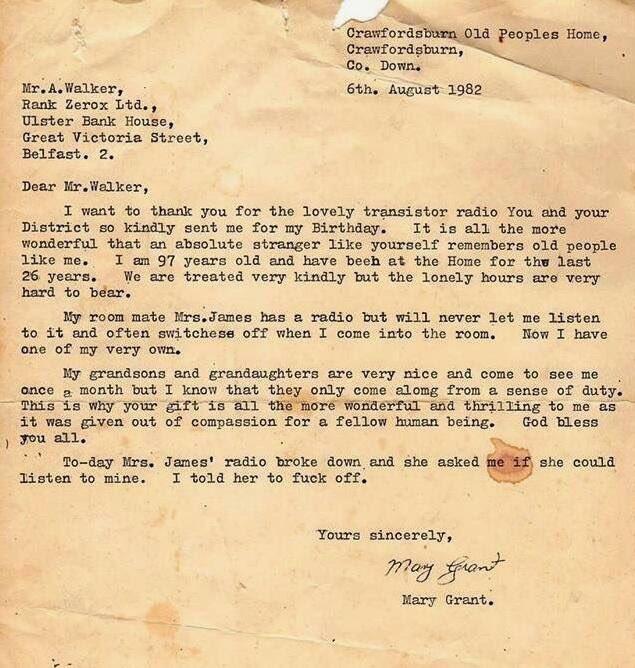
The greatest letter ever written. What a rollercoaster ride.
 1 point
 -
Looks like it was photographed yesterday. But this was around 80 years go, film and theatre star Gene Tierney. Kodachrome.0 points