


JoaMat
-
Posts
1,546 -
Joined
-
Last visited
-
Days Won
16
Content Type
Profiles
Forums
Events
Everything posted by JoaMat
-
Thanks James, my clock always tends to speed up when an amplifier needs attention. I have never used a variac when testing an amplifier. That’s way I asked.
-
Is the T2 working at 50% of the mains?
-
@HVRV, When you quote someone’s post it will appear in your post marked with the members name and time of the post in its own “window”. In that window you can’t make any changes. You have quoted me and written something I haven’t said. I don’t like that.
-
@HVRV Please, Never ever make any changes within a quote. I urge you to make appropriate changes in your earlier posts.
-
By the way... I have been made aware of that the mini T2 is marketed by a company unknown to me. They want $ 7,000 for it. It is an example of a villain's business model.
-
Vilket land är det? ¿Qué país es? Which country is it? 是哪个国家?
-

-

Megatron Electrostatic Headphone Amplifier
JoaMat replied to kevin gilmore's topic in Do It Yourself
Sorry for a really slow response. Yes, the umbilicals are identical. Some background – my first electrostatic build was a KGSShv with a PSU with on board heat sinks in its own house. Second build was the DIY T2 and I liked the chassis design. Thereafter I have only built things (almost) with off board heat sinks. With T2 I built an original T2 PSU in a Modushop case. Later I built another T2 PSU with my own designed PCBs. That are the only PSUs I’ve built, along with the first KGSShc supply. But I’ve built a lot of Kevin designed amplifiers, and all have been power by those two T2 PSUs. I found the T2 PSU with its two identical umbilicals quite convenient. With the good quality Amphenol connectors it’s easy to connect/disconnect as wanted when I want to try/test one channel at the time. What about ground loops? I’ve read/heard about it, but so far, I haven’t, or I don’t know I have had ground loops. For me it’s more important I always have a safety ground connected. Therefor I’ll continue to use two identical umbilicals … P.S. I’ve had some issues with mini T2 that was solved by removing one 580V bias wire, so I probably have had a loop. problem. But safety ground wires will stay! -
Happy Birthday!
-
Happy Birthday!
-
Happy New Year!
-
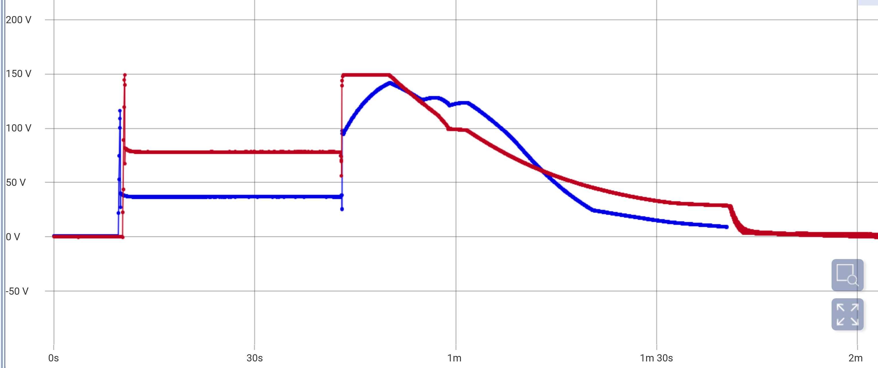
Reduced “300V section” a bit more, to 150V. Now the high voltages are +/-400V, +220V, -310V and -460V. Graph below shows voltage cross 2sj79 (Q24/25) in blue and cross 2sk216 (Q26/27) in red during power on, wait 30 seconds and power off. I can’t hear sonically differences between original voltages and reduced voltages.
-
-
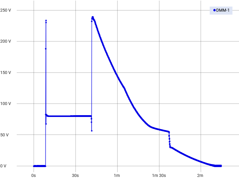
A few years ago I replaced 2sj79 and 2sk216 with ksa1220 respective ksc2690 on both Blue Hawaii and T2 and that without changing any voltages. Below chart show voltage cross source and drain on T2´s Q26,Q27 during power on, 30 second wait and power off. So far I haven’t had any ksa1220 or ksc2690 blowing up. Today I reduced voltage further on my T2 PSU, 300V section now 200V. Seems to work as good as with 300V. High voltages are now +/-400V, +220V, -260V and -460V. The reduce voltage also lowered the maximum voltage on graph above to 200V
-
A belated Happy Birthday!
-
Belated Happy Birthday!!
-
Thank you everyone. Wife and I had a nice medium long hike in beautiful winter weather. Wish you all well.
-
Merry Cristmas to you all
-
-
Megatron Electrostatic Headphone Amplifier
JoaMat replied to kevin gilmore's topic in Do It Yourself
i'm done
-
-
Megatron Electrostatic Headphone Amplifier
JoaMat replied to kevin gilmore's topic in Do It Yourself
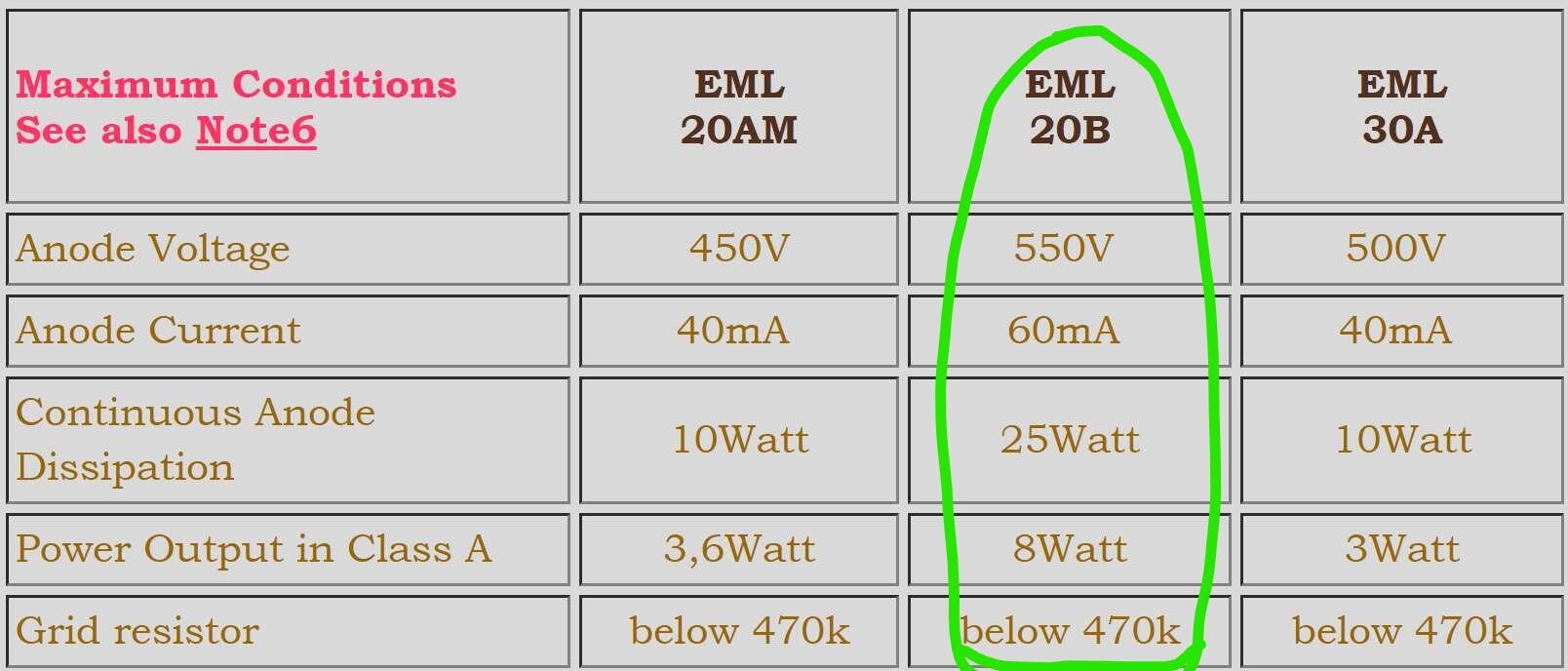
This Emission Labs amplifier wasn’t planned, it just happened along the way. Although it seems to work, I have no idea how to best use the direct heated triodes in an electrostatic headphone amplifier. Here are maximum conditions stated in datasheet from Emission Labs with note 6. Note6) Maximum conditions do not apply simultaniously. This is not a working point. I think I’m within most of the maximum limits, but what how about Power Output in Class A: 8W and Grid resistor: max 470K? Is there anything to consider in my case? Now I’m running at 400V/27mA roughly 11W and grid resistors are 680K as in the original Megatron. Any advice and comments are appreciated.
-
Megatron Electrostatic Headphone Amplifier
JoaMat replied to kevin gilmore's topic in Do It Yourself
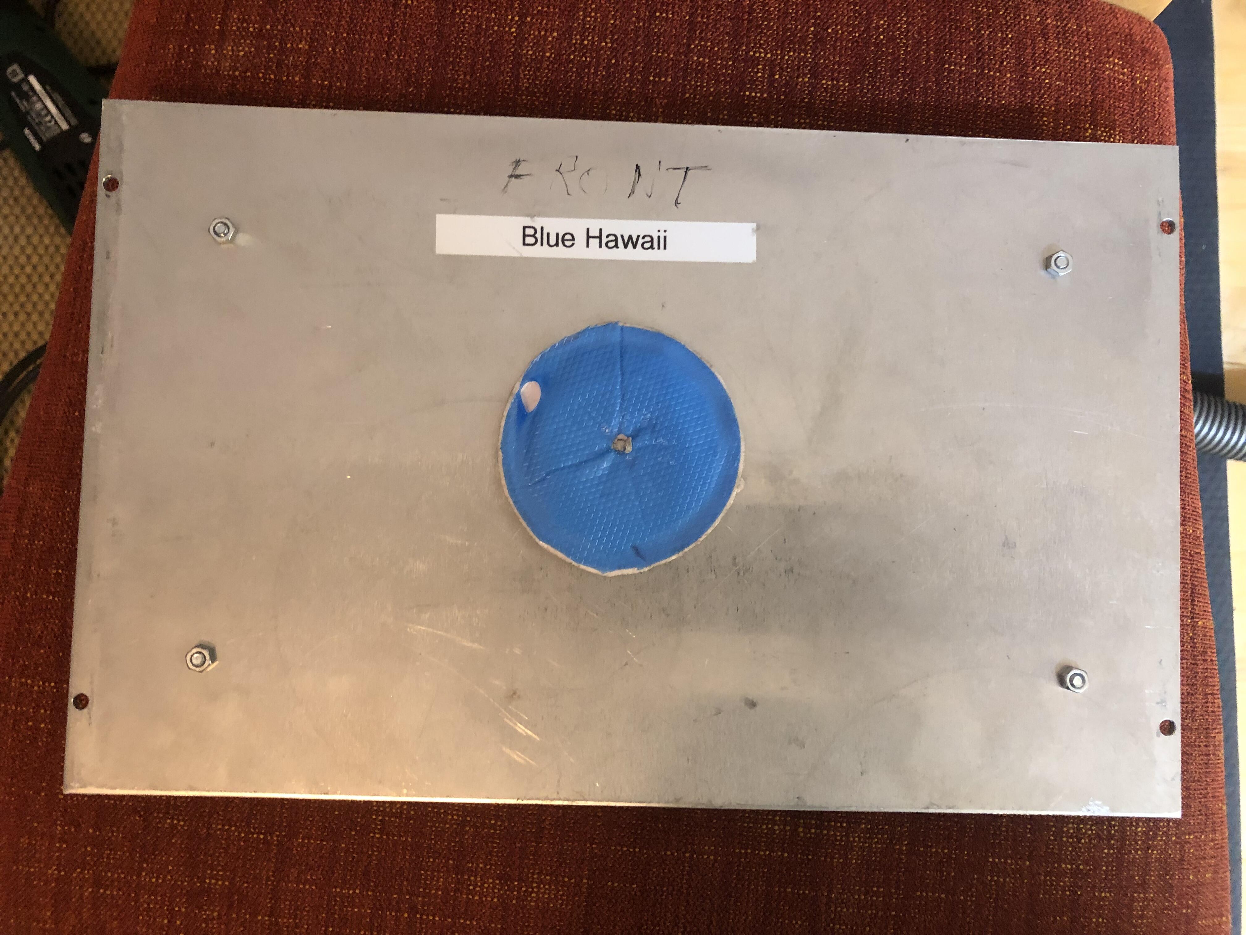
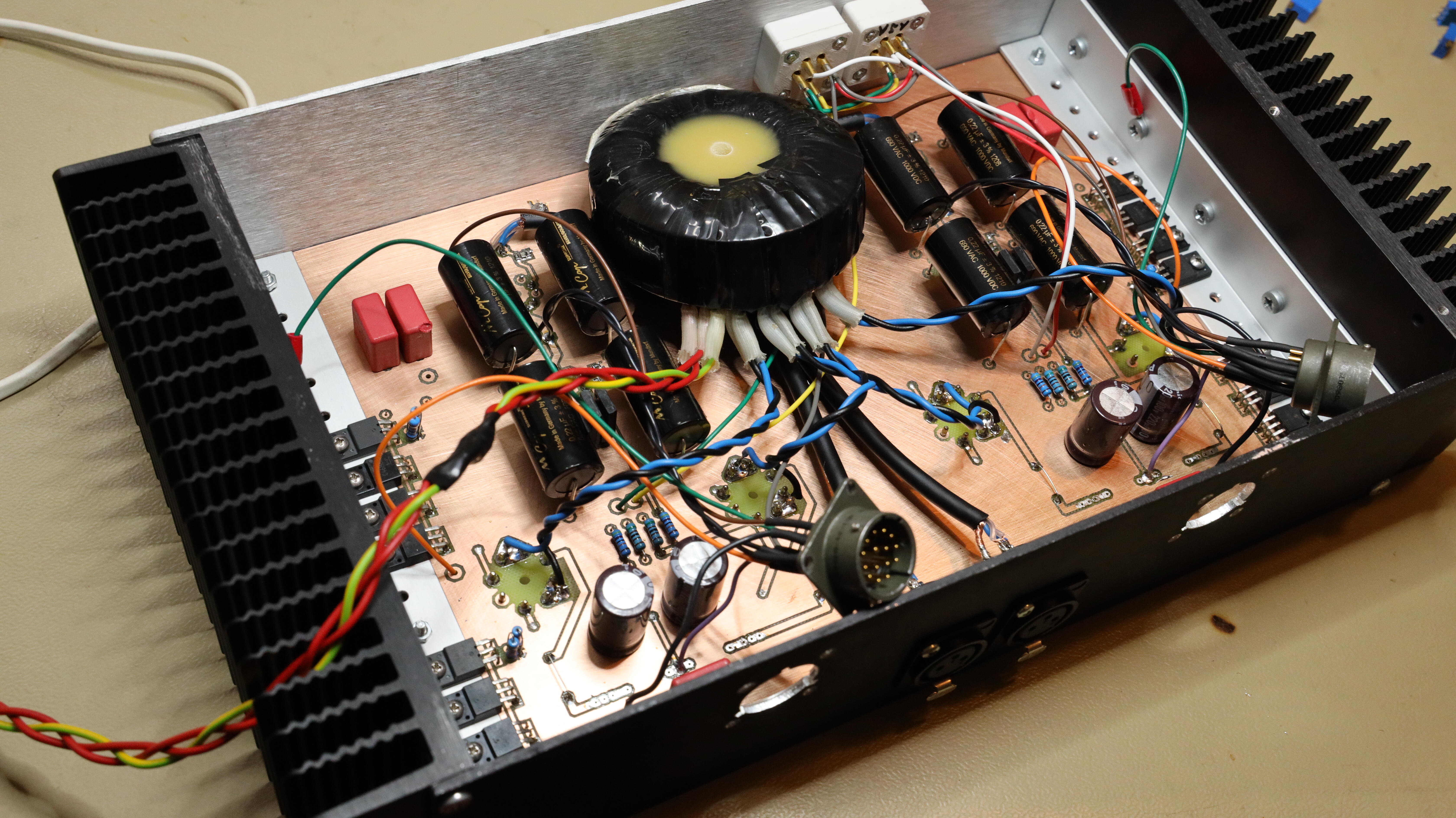
Here is my solution for filament transformer… …mounted on bottom case plate, belonged to a now retired Blue Hawaii. I also found a piece of Bergquist Gap Pad for the transformer to rest on. It seems that cathode resistor voltage is much lower for Emission Labs tube than for EL34, so I decreased the negative high voltage from 460 V to 400 V. The lowered voltage called for change of Cathode resistor and trimmer, now 402R resistor and 100R trimmer. A few things had to be removed before component changes.
-
Megatron Electrostatic Headphone Amplifier
JoaMat replied to kevin gilmore's topic in Do It Yourself
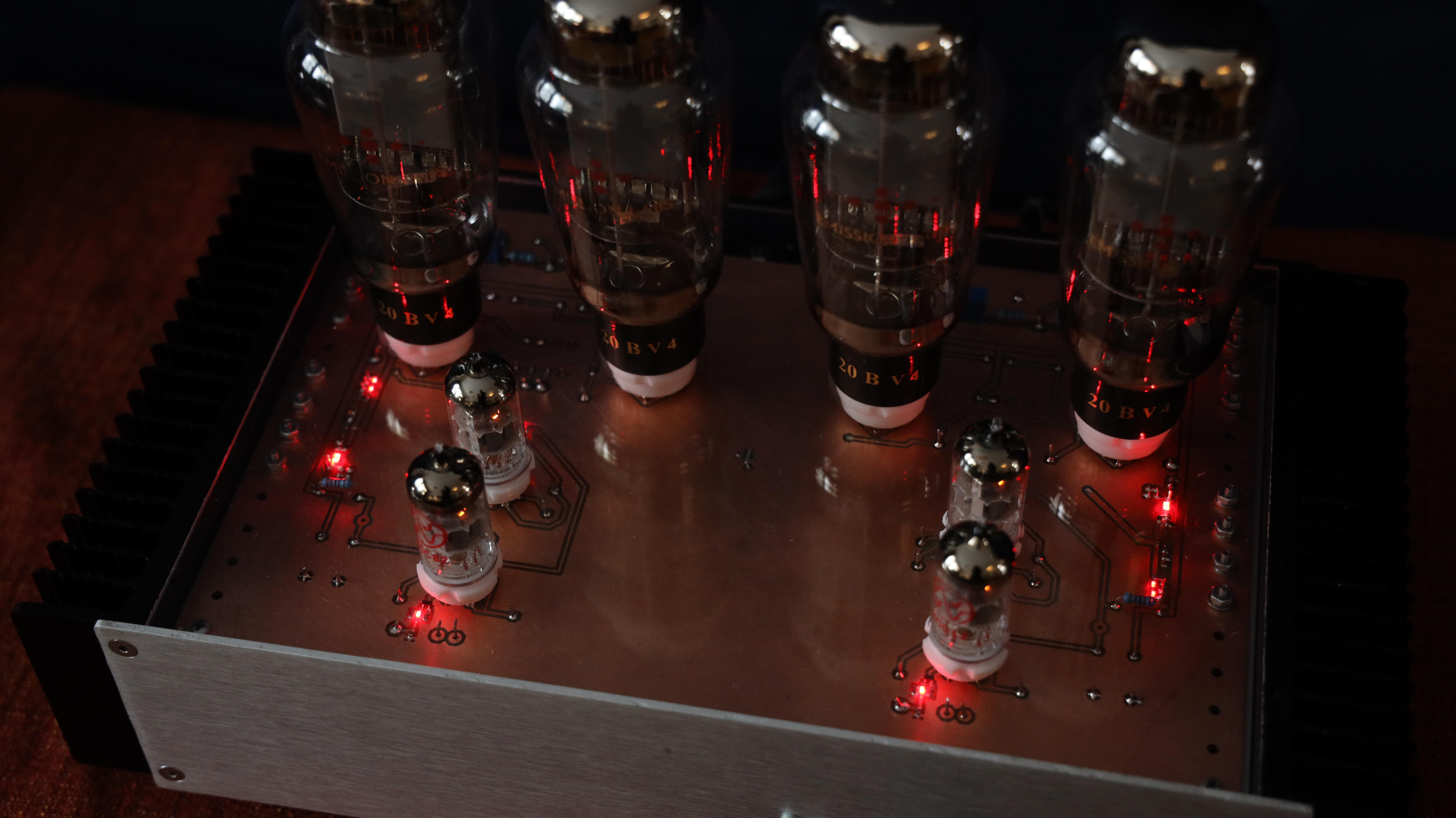
Now my Emission Labs tubes finally have gotten a dedicated DHT amplifier. Picture is taken in almost complete darkness, so most of the light comes from LEDs and tubes. Current is 27 mA which gives a voltage of 15V cross cathode resistor. Filament transformer is on the bench behind the amplifier - I have to find a more permanent solution I guess…
-
That looks great! At picture above, are you removing copper with a 2mm end mill?


.JPG.e9d82a14e65d54f960d5b4ce39632b17.JPG)

.jpg.f4872d586d2dd0f46daead3b4184fbc6.jpg)
.jpg.12f22c2c017ad2733d9667281546414f.jpg)