Pars
-
Posts
8,581 -
Joined
-
Last visited
-
Days Won
7
Content Type
Profiles
Forums
Events
Everything posted by Pars
-
+1 Sent from my iPhone using Tapatalk
-
Happy Birthday! Sent from my iPhone using Tapatalk
-
Happy Birthday Mike!
-
 My GRLV didn't have the pot, but my impression was that it was used to balance out the +/- voltages, so just check outputs to ground? Or not use it...
 -
CLOSED: Alpha/Song Huei Potentiometer Group Buy and TKD Attenuators
Pars replied to cspirou's topic in Do It Yourself
Payment sent. Paypal address is fine, and I also PM'd you the same address previously. Thanks! -
CLOSED: Alpha/Song Huei Potentiometer Group Buy and TKD Attenuators
Pars replied to cspirou's topic in Do It Yourself
Are we to pay you the amount in the Remainder column? Sent from my iPhone using Tapatalk -
Continuation of R2R DAC Discussion From Stax Thread
Pars replied to Sechtdamon's topic in Home Source Components
It sounds good, probably not as good as my 855 with an rbroer (diyaudio) discrete, but much better than the stock opamps. I have one of Colin Toole's discrete stages partly built for the 991. Still haven't decided whether to leave the ad8599 (IIRC) in as the SE to bal converter or to use something discrete there. Sent from my iPhone using Tapatalk -
Continuation of R2R DAC Discussion From Stax Thread
Pars replied to Sechtdamon's topic in Home Source Components
That is what I used on my Rotel 991 (still haven't gotten around to discrete in it yet) along with 8xxx for the buffer/SE ->bal. It was touchy for decoupling. I used the Aries DIP adapters with on pin decoupling and no sockets for the 4032s. Sent from my iPhone using Tapatalk -
Gawd, I still remember how wasted he was for KG's scotch "tasting" at CanJam Chicago. If you didn't get a hangover from that... EDIT: added smiley as I didn't intend this to sound harsh at all Sent from my iPhone using Tapatalk
-
Ryan, I think I have an extra discwasher zerostat gun laying around if you want it... pm me.
-
Happy Birthday Grahame!
-
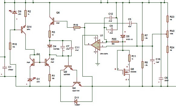
Hmmm. Built up a GRLV Plus board set for 35Vdc. Testing with a variac at ~20Vac in or so, output is around 20Vdc. However, D1 is not lit, and Q1 Vce is 0V. I've gone thru and checked that I have PNPs/NPNs in the right places, right parts, caps in correctly, etc. Changed out Q1/Q3/Q14, same problem. LED is in right as well. Scratching my head right now. Q14 Vbe 0.65Vdc EDIT: why that would be the opamp locking up Dave... Raised the voltage on the variac and things snapped right into place. 35.112Vdc out, from what I could measure unshielded on my HP3468, around 48uV of AC noise on output. DC out very stable. 36Vct split bobbin putting out 44Vac unloaded so will need to use a different transformer. Never put it up to line on the transformer, but nothing running hot. Dropping around 14Vdc c-e on the pass transistor at 40Vac input.

-
Yep, oops had those flipped. Thanks!
-
Pretty soon your going to be telling us that you are now implementing all of Machina Dynamica's wondrous products and inventions Good that the rollerballs work well. Sent from my iPhone using Tapatalk
-
Happy Birthdays guys! Sent from my iPhone using Tapatalk
-
I think it is the LSJ489/LSK689 that are the matched pairs. For a reverse taper pot, can't you just connect a regular log pot backwards (In to the pin normally grounded, ground the pin that is normally the in pin)? Or am I mistaken?
-
I think that luvdunhill and I were mentioning Arrow. I used them for the semis on the GRLV. I just got a 15% off code from them today, valid for the next 5 days 15-GDKP-DS Sent from my iPhone using Tapatalk
-
Vibrapods?
-
Just curious Kevin, but have you looked at putting the pot either midstage or at the output on your designs? I realize this is probably no-go on electrostats, but on the dynamic amps might loosen 10k only problems? I know Pass does this some, but requires even lower values (2k on Pass Aleph P pre for example). The guy doing the Neurochome HP-1 also seems to advocate this. Sent from my iPhone using Tapatalk
-
Yes, those are some of the parts I added for myself. Like I said, I added lots of optional parts in that BOM. Just use the original BOM and you'll be fine with changes for R8/R9.
-
I was building a single plus up for 35V out, but not done yet. Spice models are notorious for doing this kind of stuff, particularly when the user is a novice (re: idiot), so I wouldn't worry about anything I said above having any basis in reality. Should work fine. Is yours for an ssdynahi?
-
35V would be fine, 25V also. I am looking at a Spice model I got from Kerry which seems to oscillate once you change the gain to something other than the stock 1.5K/1.5K. I'm sure it is something in the model (a device model). I know luvdunhill has one as well, and he told me the same regarding the tantalums (25V sufficient for most outputs).
-
Sounds right. What transformer are you using? Also, what voltage tantalums (10uf/47uf)?
-
Pffft. How can you do cable rolling without it? You know you need those pure-silver-spun-by-nymphs-in-the-rainforest cables that cost more than the phones...