Pars
-
Posts
8,601 -
Joined
-
Last visited
-
Days Won
7
Content Type
Profiles
Forums
Events
Everything posted by Pars
-
Hmmm, re: caps. Does that actually do anything? Thinking of changing these to ground? I'm running 4 devices (2 pairs). Sent from my iPhone using Tapatalk
-
Someone might have posted this before, but remastered audio, live 1973 performance
-
One other question... looking at the board layout for these, I noticed that the 220uf/100V caps up by the FETs are run from V+ to V-, not V+ to GND and V- to GND. Is this correct?
-
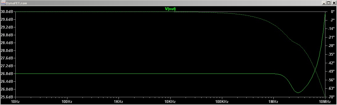
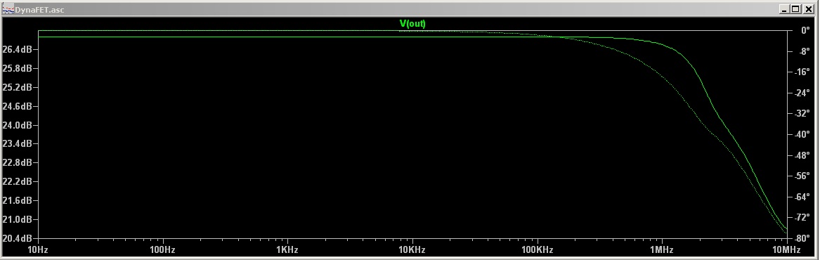
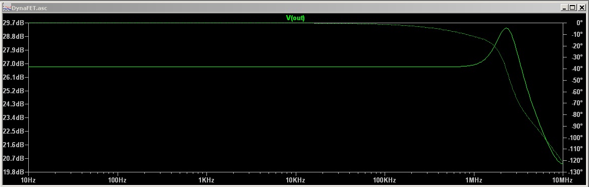
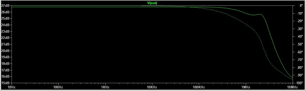
Ran some Bode plots in my spice simulation. Not completely sure how to interpret these yet. Haven't installed the zobels yet either (in the actual amp). I have them in the simulation; I'll have to run some of these with/without them and see what differences I can see. At any rate, some below: Standard 1K/100R feedback loop, 10pf compensation cap Same 1K/100R feedback, 33pf compensation 10K/1K feedback loop, 10pf comp. 10K/1K feedback loop, 5.1pf comp

-

Continuation of R2R DAC Discussion From Stax Thread
Pars replied to Sechtdamon's topic in Home Source Components
A cap farm! That one would be a fun recap, though I doubt you guys keep stuff long enough to need to do that Sent from my iPhone using Tapatalk -
Yes on both questions. Pm me if you would like a board. Sent from my iPhone using Tapatalk
-
Yes, very nice tribute Brent!
-
The ferrite beads seem to have no effect. I decreased the feedback resistors to 10K/1K (still the same 10pf compensation cap). Oscillation is still there, though I now have to turn it up a bit further before it begins. Waveform looks slightly different as well, but I didn't recheck frequency. The spice simulation doesn't behave exactly like the real world circuit (big surprise), but does seem quite picky regarding the compensation cap. The 10pf works well for the std. 1K/100R feedback network. 5.1pf seems to work well for the 10K/1K network, and 1pf up to about 4pf works for the 100K/10K network. I'll play around with the compensation cap in the actual circuit. Now for the interesting part: since this only occurs with some crappy phones plugged in, I tossed a zobel together with a series 20R MF resistor and a Wima 0.047uf cap. This completely killed the oscillation. I'll get some more appropriate parts per Amb's b22 parts list and install. I don't know how to do Bode plots nor take the measurements necessary for one in order to try to figure out exactly what is going on in the amp. At least that is my guess as to what it would take to really nail down the actual cause. Any advice here appreciated!
-
Just power it from one of the amp PSUs, though I can't remember what the Protector's input voltage limit is. I assume your Dynahi is at +/-30? Check on the Protector... EDIT: the boards have 7812/7912 regs on them, so the input voltage limit would be 35 Vdc. Sent from my iPhone using Tapatalk
-
Took a look tonight at it, and the oscillation is repeatable. If I am remembering how to do these things correctly, it is at ~5.2MHz (3.85 divisions at 0.05 uS/div). It is also at around 15V p-p, but a really nice sine wave. Inverted in one channel (the DynaFET seems to be non-inverting from what I saw; the Dynahi board must be inverting). I'm going to try some ferrite beads; I have some surface mount. Working on this, do I ever dislike the black soldermask now
-
Getting back on subject, I decided to try to evaluate the noise I was hearing. I hooked up one of my dynahi boards for the other channel and took a look at things on the scope. Both channels (FET/BJT) had some noise on them, so inconclusive. Since I don't have a function generator, I was using a portable CD player with a disc of hi quality test tones. When I unplugged the AC adapter, the noise diminished noticeably, but not completely gone. From what I recall, the dynahi was quiet when I was testing it. I'll need to recheck this with both channels to verify and make sure I'm not chasing my tail. Since my previous (4 years ago or whenever) testing had shown that the FET amp board went nuts with the crappy headphones I have in the shop for testing, I have had these plugged in most of the time. I replaced the feedback resistors with the original 1K/100R combo. Now things got interesting. Without the source plugged in (RCAs), I was getting a sine wave on the outputs (both boards!), at all volume positions other than all the way down (full attenuation). I did not determine what the frequency was, but strangely it wasn't really audible on the phones. I am theorizing that the FET board is oscillating and this is feeding back thru the PSU? Not sure how rational that is, but that is all I have to go on right now as there was no input plugged in, it remained with or without the headphones plugged in, and the only thing common besides the pot is the PSU. Next time I look at it I will verify that it is behaving consistently, and then go back to the 100K/10K feedback resistors. Maybe see what 10K/1K does as well. Any other suggestions? EDIT: I asked Todd to move this thread from the Casino to the DIY forum, and he obliged in doing so. If there are objections to this let him know (or me).
-
Whats the right size transformer for the original dynahi PSU
Pars replied to sbelyo's topic in Do It Yourself
No the PSU is performing just fine, but running a bit hot because of the higher input voltage. S22 requires more overhead on its input voltage than a GRLV does. Since the transformer is putting out ~37Vac, the raw DC after the rectifiers is ~51Vdc, giving around 20+ V overhead which is dropped on the pass devices. I believe the Antec 20V transformer I am using on my Dynalo is putting out right around 20Vac, so just under 27Vdc for 6.x V drop with a 20V output. Runs fairly cool. Anytime you use a larger transformer than needed, it will run at higher voltage than spec (part of the regulation spec given). The Antec is a 50VA while the SumR is 120VA. Supposed to be 14% regulation but this one is outside of that. I am going to build a GRLV for the Dynahi and might grab a 100VA Antec and get rid of the SumR. Sent from my iPhone using Tapatalk -
More worrisome are the actions and belief system of the stepmom, Dyna Mo Hum...
-
Promising... actually listened to single channel on some crap phones tonight. My scope isn't showing anything bad (though I think my scope may need recapping). More testing, etc. necessary. One thing I do have is some hum/buzz; this increases with volume until the pot gets past 90%, then decreases to nothing. No buzz all the way down either. Not sure if this indicates noise/oscillation or not, but what was on the scope wasn't conclusive. One other change not mentioned above was increasing the feedback resistors from 1K/100R to 100K/10K (R56/55). I noticed that on the schematic for the SuSy DynaFET that feedback was shown as 200K/10K; I assume this is mostly to increase input impedance, but figured going higher might not hurt. I'll switch it back and see what effect that has.
-
I think he said HE was going to build it, not John...
-
Continuation of R2R DAC Discussion From Stax Thread
Pars replied to Sechtdamon's topic in Home Source Components
Something wrong with Ideal T-strippers? Mine are 30+ years old and still work just fine, including teflon, which is pretty much all I use. -
Being a glutton for punishment (and since I was messing with my dynahi anyhow), I decided to take another look at this. Nothing yet, other than a few observations: I built an LTSpice model for this (attached, change extension to .zip), which seems to work. I think I found good enough models for devices. In DC testing, some of the BJTs in the DB sections are running rather hot (55C). Q19/Q22 and Q23/Q26. Bias for 4 output devices is ~80mA per device. Current configuration of the Vbe multiplier is 2.2K for R17/R18, 1K for R62 (not on Eagle schematic but in series with TR3), and TR3 = 20K. Adjustment range of ~88mV or so low to > 150mV. Current source resistors are 1 ohm but probably going back to 2 ohm. I currently have 1K gate stoppers in, but have not tried running signal thru yet to look for oscillation. Eagle files as I have them are available on request. Not completely correct, but close to board. I'd like to have this thread moved to the diy section, unless someone objects. Hard to find here. Dynafet ltspice.doc DynaFET_schematic.pdf
-
Happy Birthday Jeff! Sent from my iPhone using Tapatalk
-
Whats the right size transformer for the original dynahi PSU
Pars replied to sbelyo's topic in Do It Yourself
Bringing this thread back. Was playing with my dynahi/s22 combo this weekend and put larger sinks on the s22 as things were approaching 70C. Started measuring stuff and loaded with a pair of dynahi boards set at 75ma the transformer is putting out 37Vac. SumR 120VA, 2 x 30. Regulation seems to be kind of poor even though it is lightly loaded. Sent from my iPhone using Tapatalk -
Or refuses to go like Bennett. Fat chance though. And it was a really good game, and was the only one in our family rooting for the Pats. I would have been fine either way though. Almost quit watching in the 3rd when it was looking like a blowout. Sent from my iPhone using Tapatalk
-
This is what I have used for several years. I think the DA10 is the insert that I have. Focal distance is a bit close at 4". http://www.doneganoptical.com/products/optivisor
-
Very nice!
-
Have fun in NYC all! And avoid the red vodka Sent from my iPhone using Tapatalk
-
Sent a pm to one of the mods over there regarding this (didn't know which "jude" was jude.) Banning imminent I suspect Also, I assumed that no one ever asked one of the Fla. crew for their permission to use the name? Sorry, this has bothered me for quite some time (1st world problems, I know...)
-
Commercial trade show should pay Fla. crew for the use of the name Retroactively. Sent from my iPhone using Tapatalk