


luvdunhill
High Rollers
-
Joined
-
Last visited
Everything posted by luvdunhill
-
Thanks Kerry! If anyone is following along at home, here's the Atmel version of this part - CSTCE8M00G52-R0. It is NRND though
-
Well, I have some space left on the board! I am seriously considering adding one of these to the bottom: https://datasheets.maximintegrated.com/en/ds/MAX11301.pdf I think I can keep it all 2-layer as wellGetting this on a two layer board the same size as the PS will be fun. Any suggestions on a crystal that is smaller and perhaps doesn’t need external components? Smaller opto isolator recommendation? Don’t need anything fancy will just accept DC voltage for the trigger input.Ok, here's the schematic for the control board. A few questions: 1.) I've never used a MOSFET pull-up in the manner described on the 1-Wire circuit. Does this look correct? I figured I might want a dozen or so external temperature sensors, so I wanted to beef this up 2.) In general, am I using the "right" uC pins? I tended to randomly assign them, but I know that there are specific pins suited for different things (ADC, D, UART, etc.). A pair of eyes on this would be great. 3.) I'd like to use this bootloader, https://github.com/micronucleus/micronucleus. Any reason to think this wouldn't be compatible? It looks like it might need an external crystal, I have that. 4.) Eyes on the MOSFET relay driver? I wanted to be able to drive high current things like SSRs, etc. 5.) Other features? Better name?
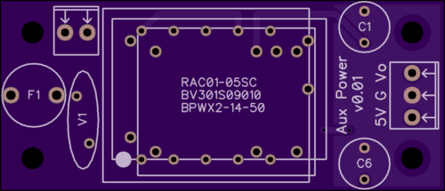
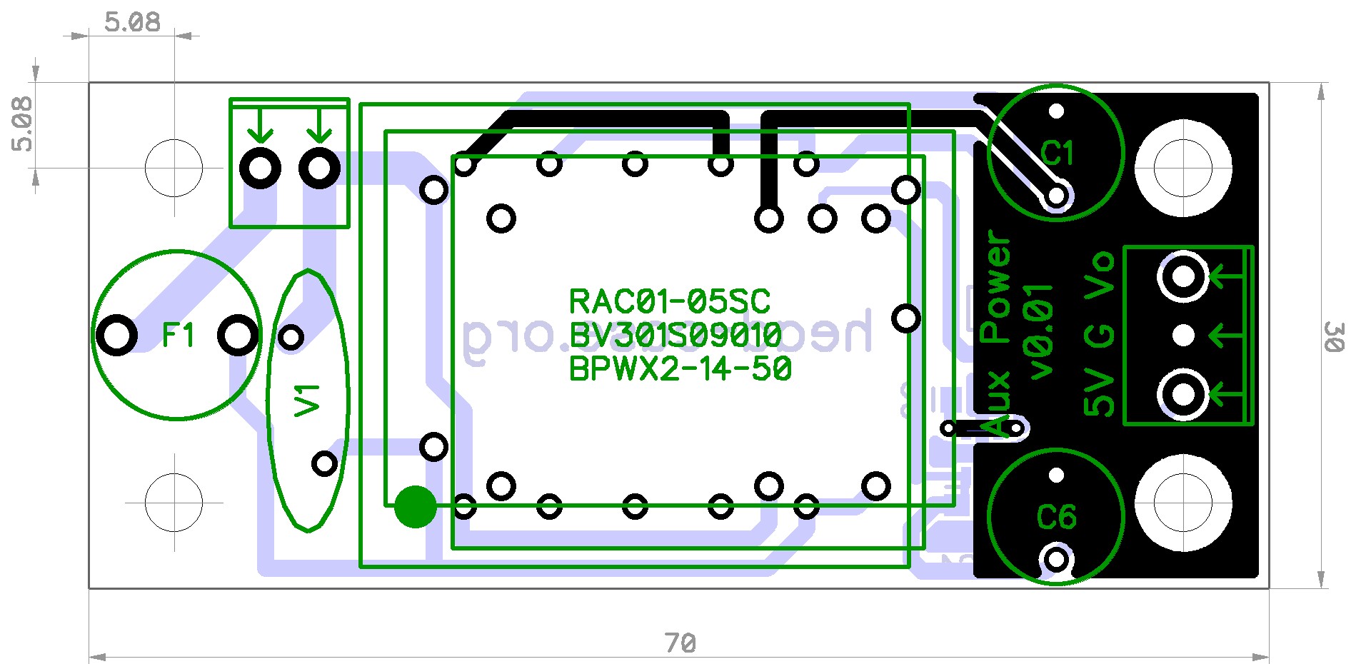
 Power supply boards showed up! I haven’t placed the order for the AC/DC modules, but had these EI transformers around and they fit just fine.Pfff... needs Dr. Wood logo somewherehttps://sme.co.uk/2018/05/01/sme-limited-acquires-the-garrard-audio-brand/For the feedback cap? The original schematic has this as 10uF?Ok, three on the way. Next up is the control board!Since when did people care about speaker building here? Heh. I want to get back and measure the speakers and can post info here - I did a similar speaker with Jordan JX92S a while back and these are similar idea but larger box. I can post both designs if folks care. I have a third design with Raidho ribbon but screwed up the boxes and haven’t gotten around to fashioning some nice pieces of wood to hide the mistake (I mixed up the top and bottom of the speaker when working on some stand attachment mechanism) I should do that sometime!Exactly. I worked carefully with the do not allow traces regions on the switchers and they will work just fine and it turns out to be a useful little board. I think I need to mirror V1 (MOV suggested for 220V operation), add an mains input label, and change the 5V output label to Vr (in case a 3.3V regulator or other fixed output regulator that works with low ESR caps, such as the LP2992, is used). A little bit more copper for the regulator would be nice as heat is dissipates through its pins. Also need to add polarity makers to the caps - I didn’t have this size in my library, oddly enough. I will make the changes this afternoon and order 3 and make them up. I need to double check that the 20A relay I am eyeing will fit on the same dimensioned board. The other parts are all SMD, including the micro controller so they will fit in a square inch top and bottom.ok, here's a generic auxiliary power supply. what does anyone think? any additional features you would like?


 It’s a ported box, a bit smaller than 0.75 cu ft. Dayton Audio with BG ribbon. I can post more info in a bit, heading out of the house.Also, both those drivers are magneticly shielded - so no fear putting sensitive things nearby [emoji4] First time really pushing the boundary of a woofer up to the higher end, had to control cone breakup in the crossover, but curious how it ends up. One huge benefit is a wide sweet spot and great imaging. It does simulate well, that’s all that counts, right?Elecrow and PCBWay.Nice!Kerry, what is feeding these during the testing (bench supply?) and what is the load? Would you be able to do some measurements with some decent ripple in the input (say 500mV) and a decent load (1A?)Kinda cute finding. The best matched JFETs from my pile, when stuck in the final circuit, result in -92dB THD and -84dB THD+N off my battery powered oscillator. That’s 0.0025% THD. The worst possible match (deliberately bad match) is -82.6dB or 0.0075%. Now, the offset trimmer value can be used to find the better performing circuit, as out of the 8 finished buffers, this trimmer value when DC offset is at zero, is directly proportional to the resulting THD value (this is because these JFETs aren’t really good complementary devices and so it all makes sense, just randomly noticed this when double checking some voltages)The new Esoteric K-07x is worth considering. The “x” upgrade resulted in a completely different sounding “house” sound, no longer sterile and clinical. It’s possible to adapt the JDM version by replacing the transformer, if you are handy at the DIY.More buffers - 10 transistors per board! [mention=431]Pars[/mention], interested in my two purple prototypes? Rails are 5v-50v and implements a kind of sliding bias (bias increases when load increases) centered around 10mA. They are DC coupled and low distortion. I will run all the new ones through the distortion jig in the morning and see how close they are.Is the opto CTR important at all? I have some CNY17 in a few grades on hand. I use these to bias some output devices in power amp design. Ok, you have convinced me. I will get it queued up in the project list [emoji4]Interesting, I added a simple trimmer here instead. Would these modifications work with the default batterys? I would think so. I am tempted to try these changes out [emoji4] What working voltage is needed for the 10uF cap and the one in the same position for the previous schematic (feedback/integrator cap)?Will do in a bit - no components, but pretty cheap. Info here: http://www.diyaudio.com/forums/showthread.php?t=313775





Important Information
By using this site, you agree to our Terms of Use.