

All Activity
- Today
-
Here's a fascinating (at least to me) series of lectures by one of my heroes - Richard Feynman. These are all about an hour long, and I was enjoying his engaging talks about diverse topics. For example, below. You get a flash at the beginning that I missed. But at the bottom it is Feynman Reborn, an AI Feynman, along with unmistakably his voice. There is a list of publications at the bottom (for example the Feynman Lectures on Physics). There is a series of these, and the only real hint that something is up is if you look at the background. I think that the authors of the AI Feynman left a really weird background to give a sense of the unreality of the superb AI Feynman.
-
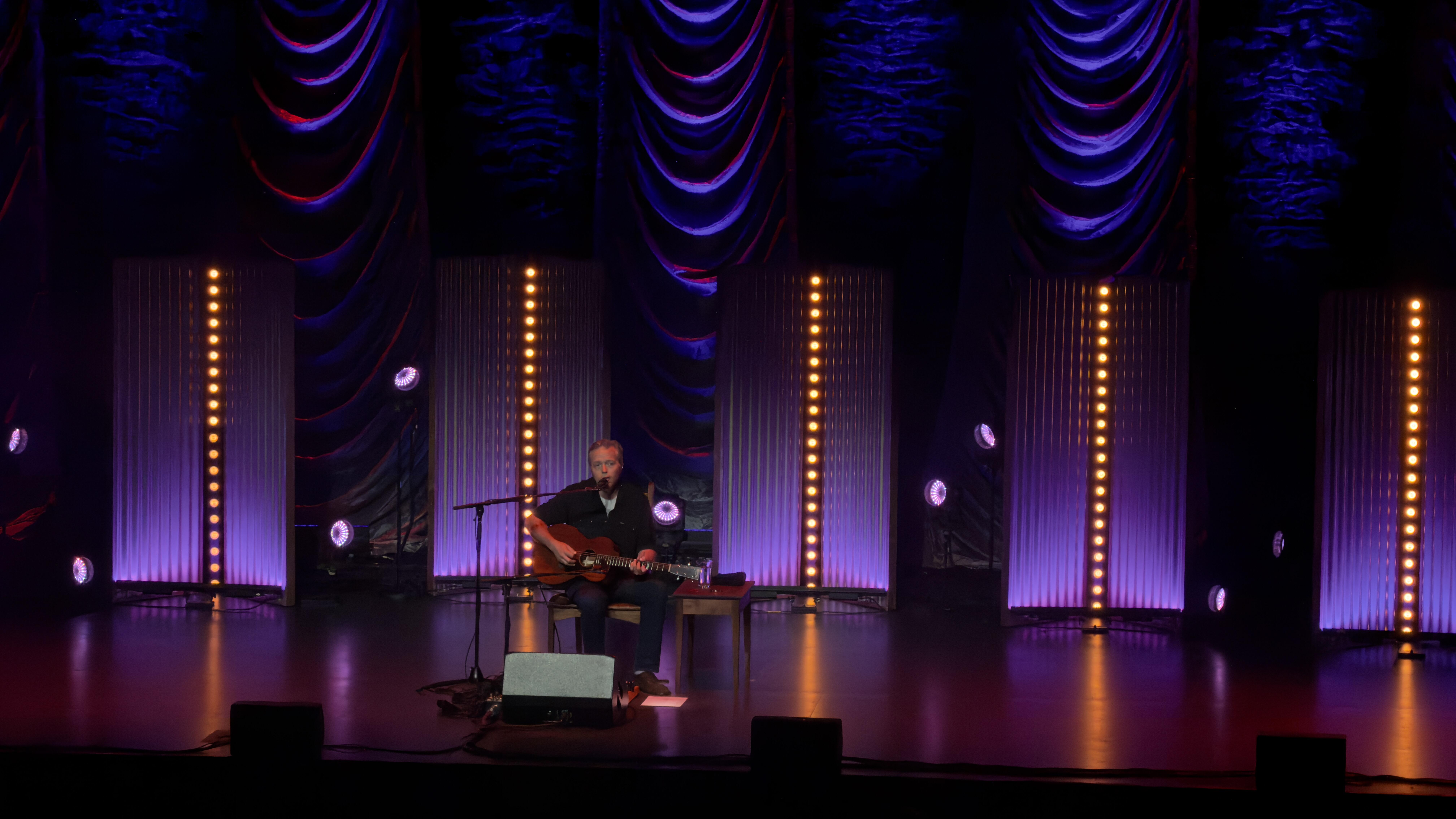
Two nights of Jason Isbell in Knoxville



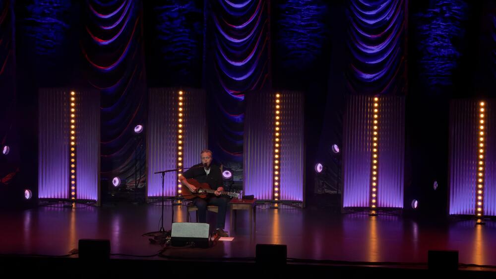 He's clearly sporting a Manssiere
 Great job Adam! You're definitely ready -- especially for a supported ride with breaks and refueling stops. Impressive progress!
- Yesterday
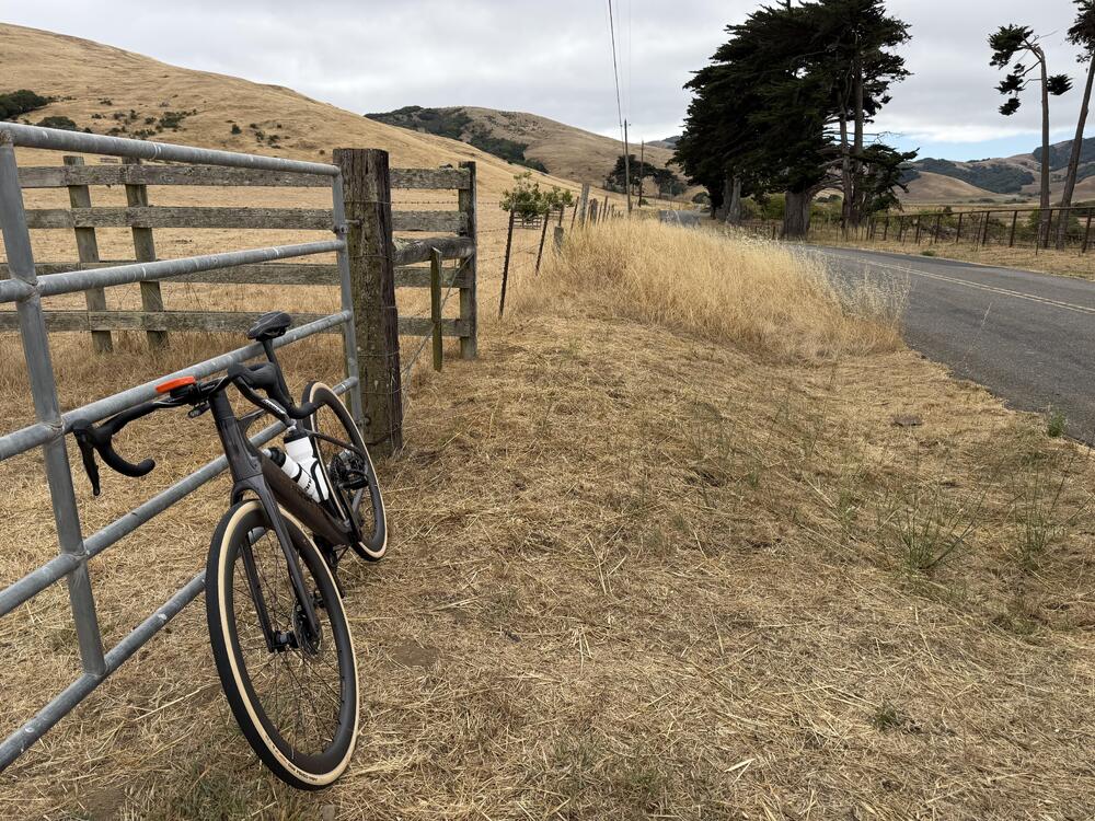
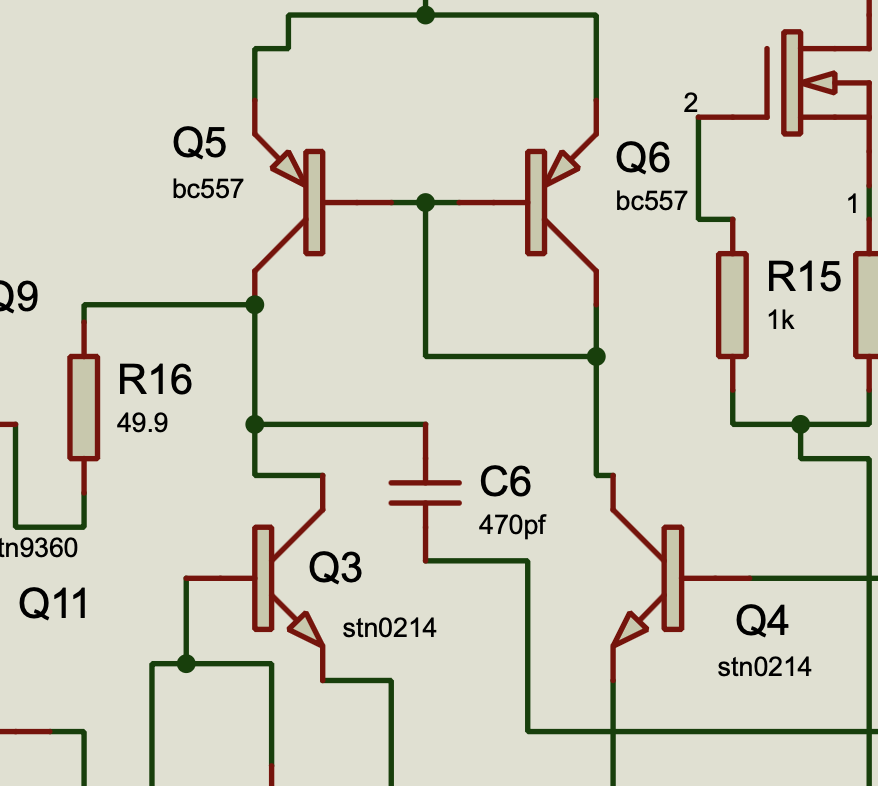
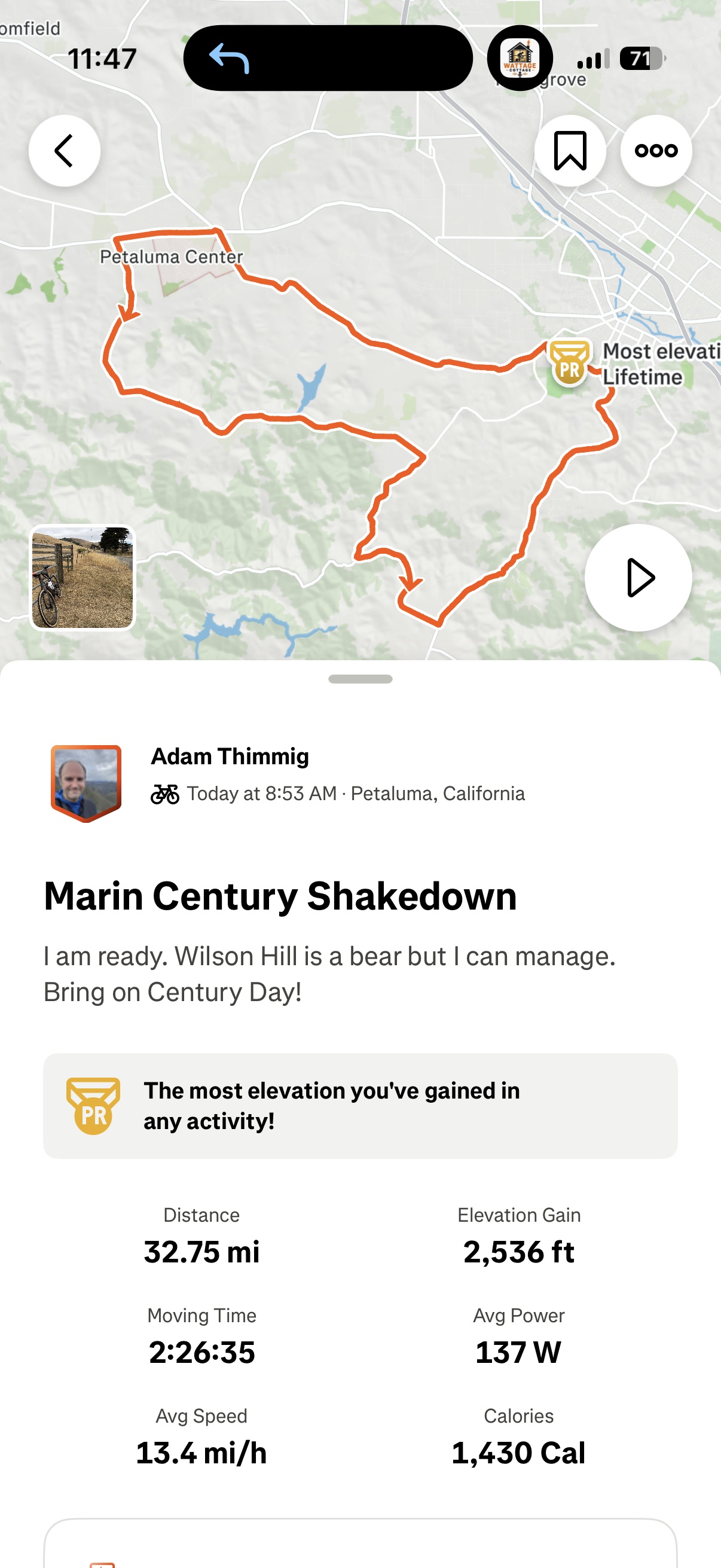
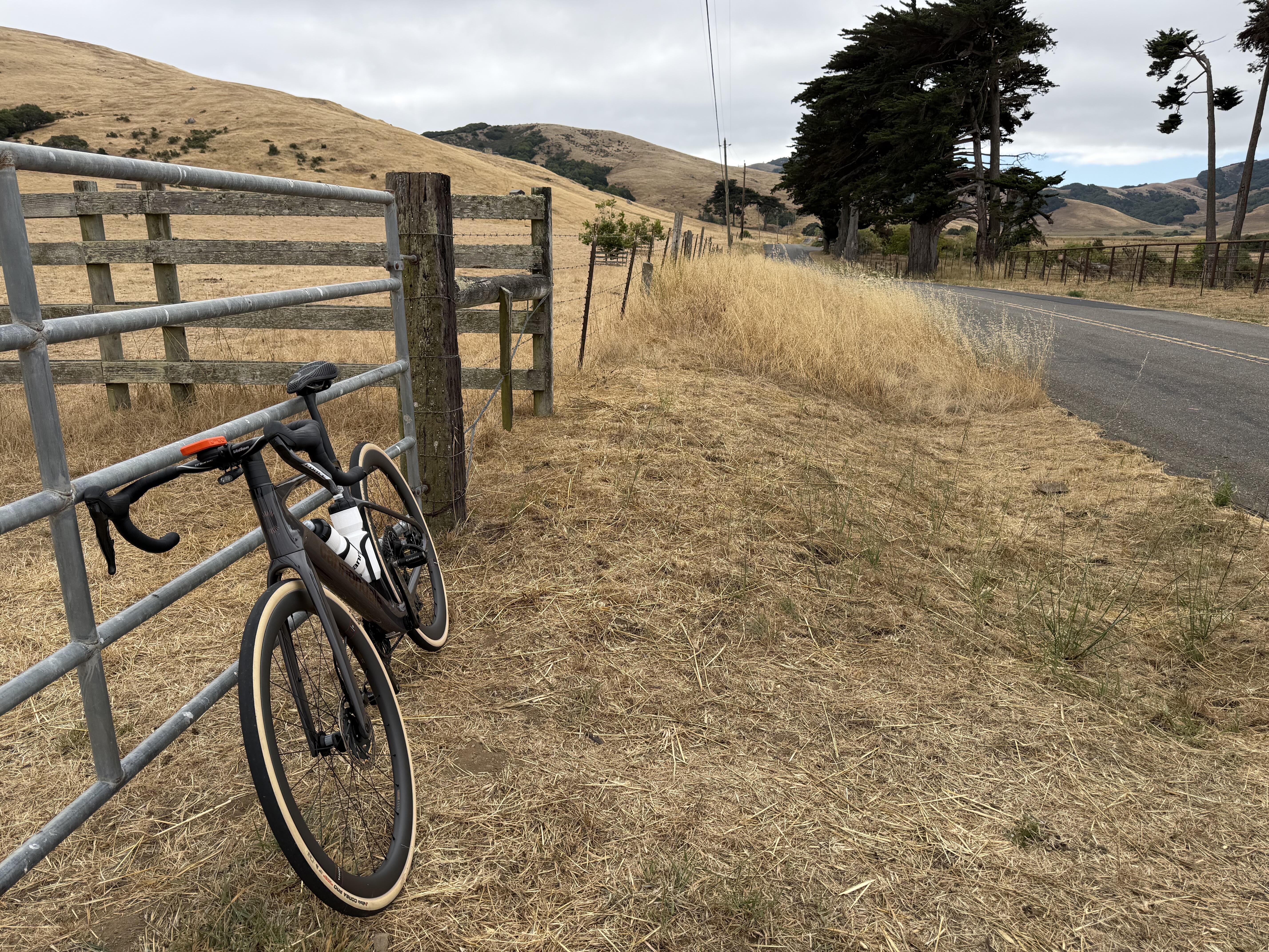
Yes, it’s the C6 470pF capacitor in the power supply. I originally installed a 5pF capacitor instead of the specified 470pF. After changing it to 470pF, the output voltage rises very close to the raw DC input. My raw DC is about 698V, while Vout increases to around 675V, instead of regulating to the expected 600V.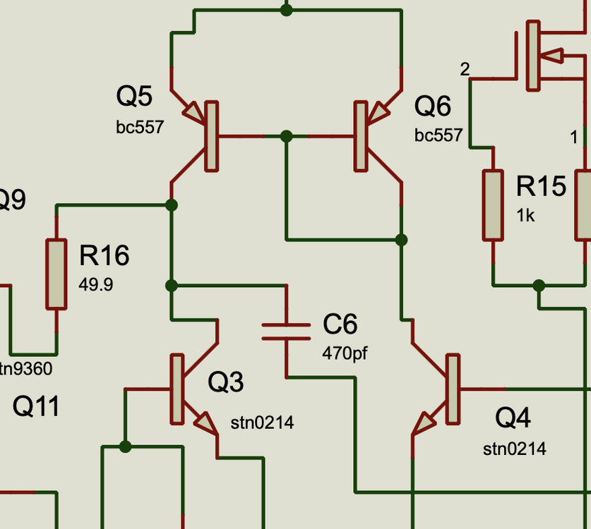 Did a final big shakedown ride before the Marin Metric Century in two weeks. I didn’t want to see the hardest climb (Wilson Hill) for the first time on Fondo day. It was indeed a bear, but I am ready for this. The training has paid off. Should be a fun century. West Marin is pretty damn good riding when you aren’t on the major through roads.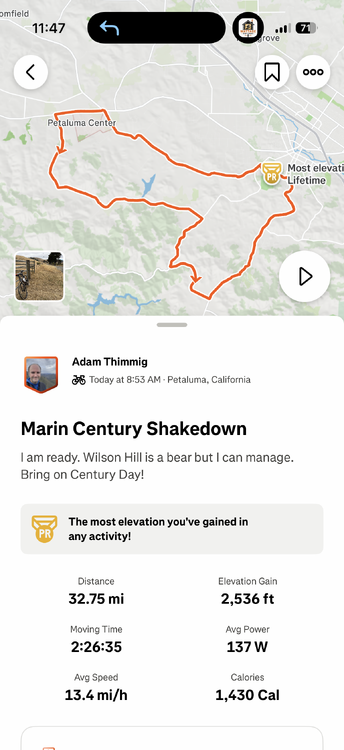
 OC shitpost:
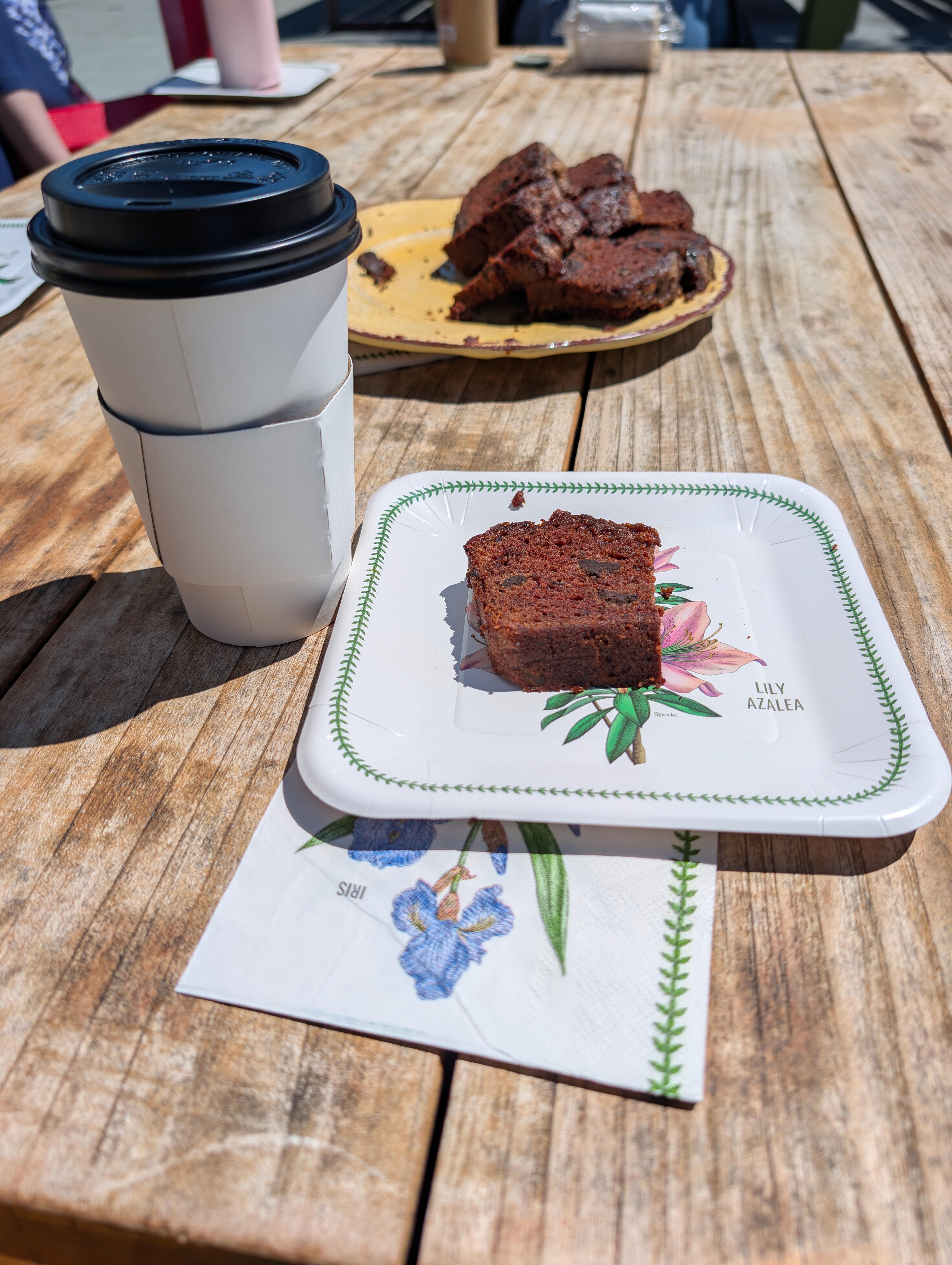
 Double Chocolate Banana Bread with the Brits.
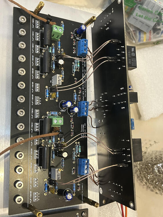
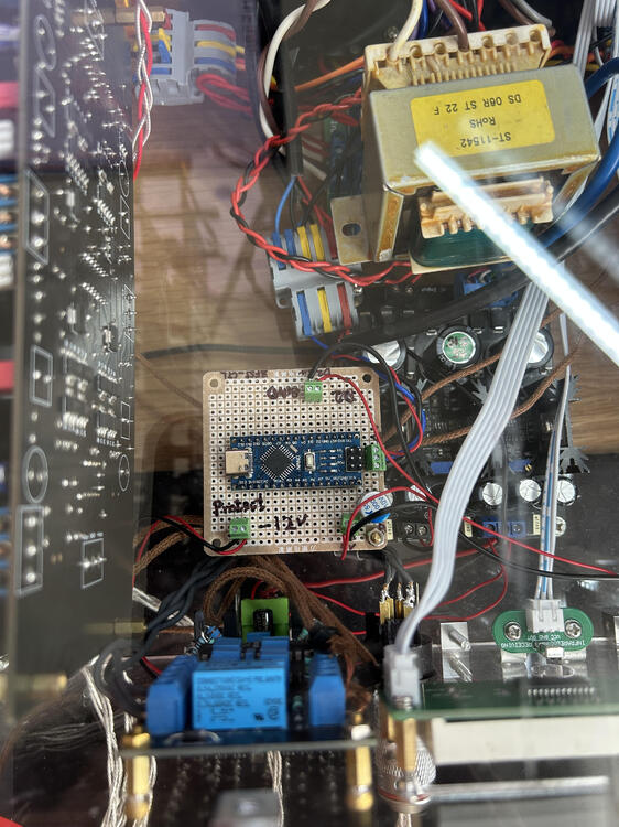
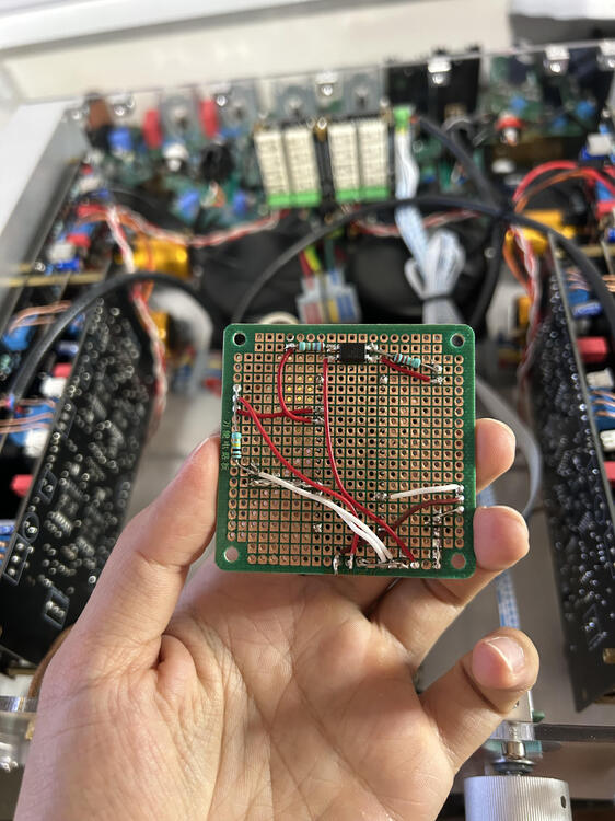
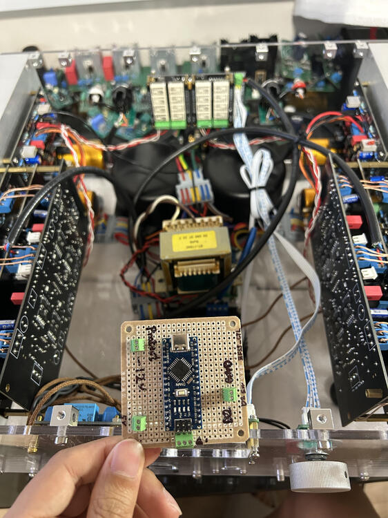
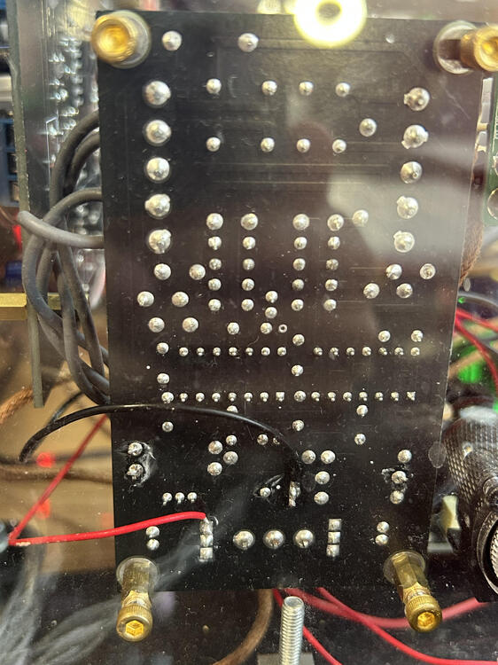
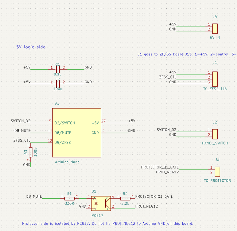
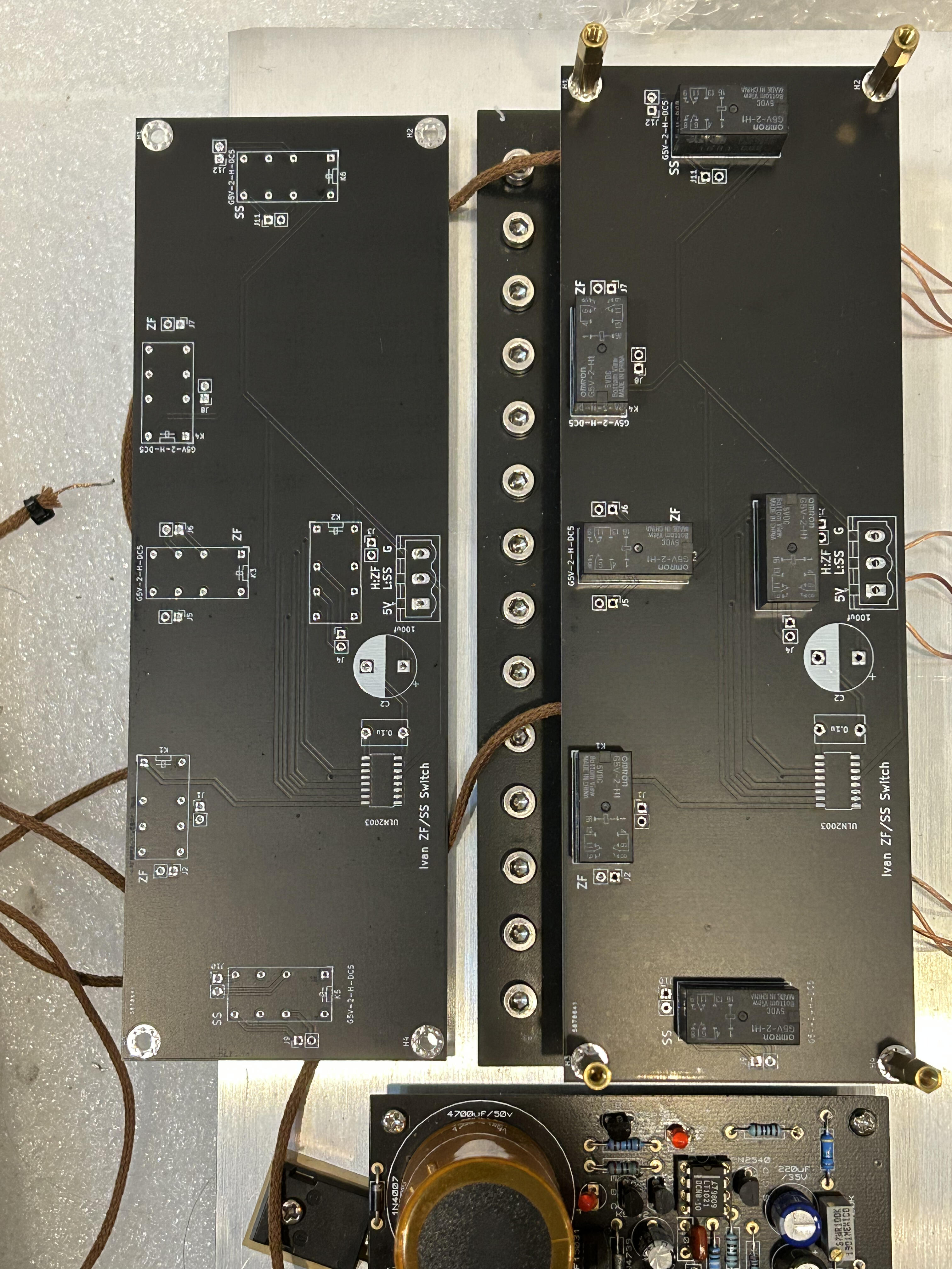
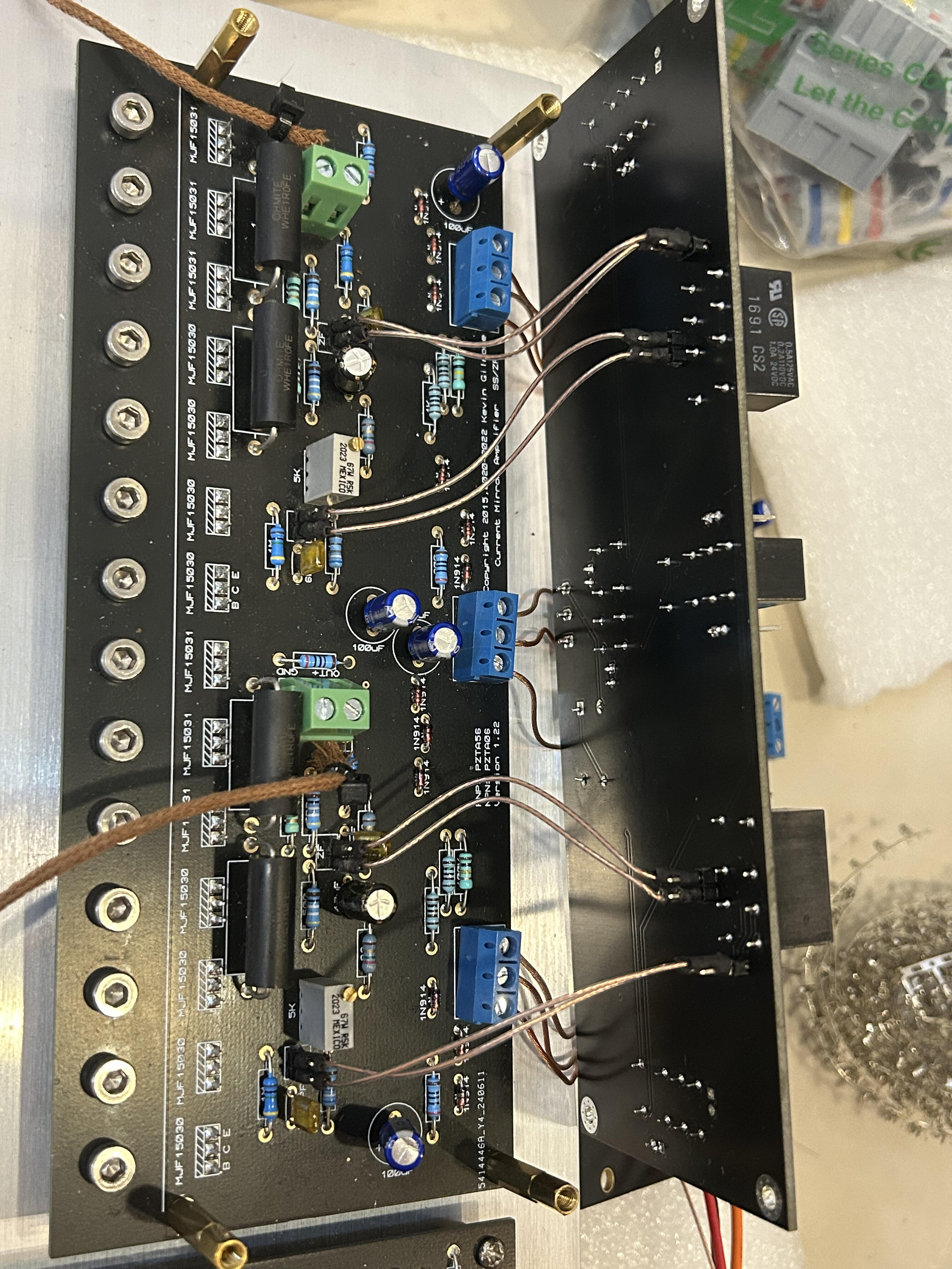
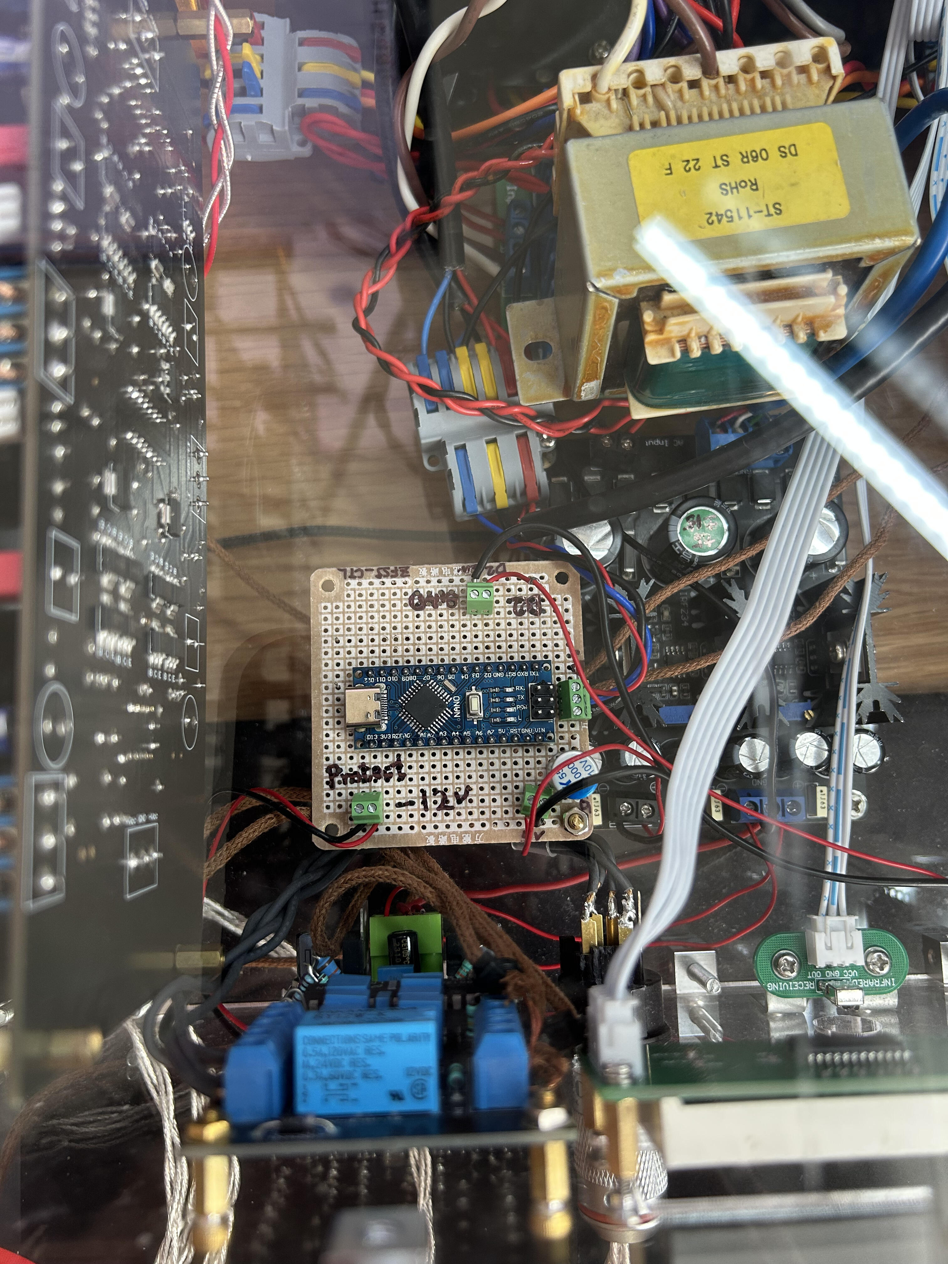
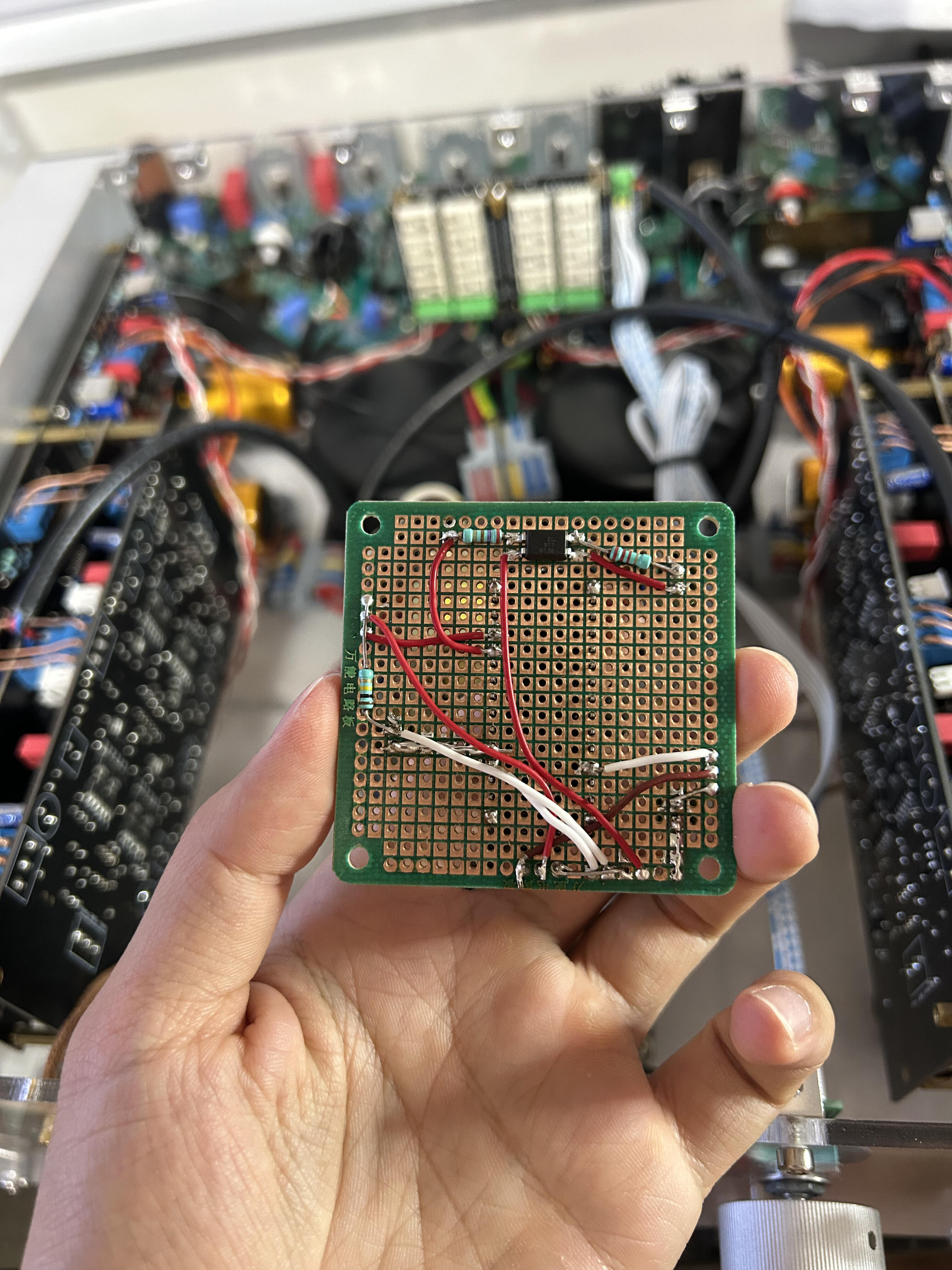
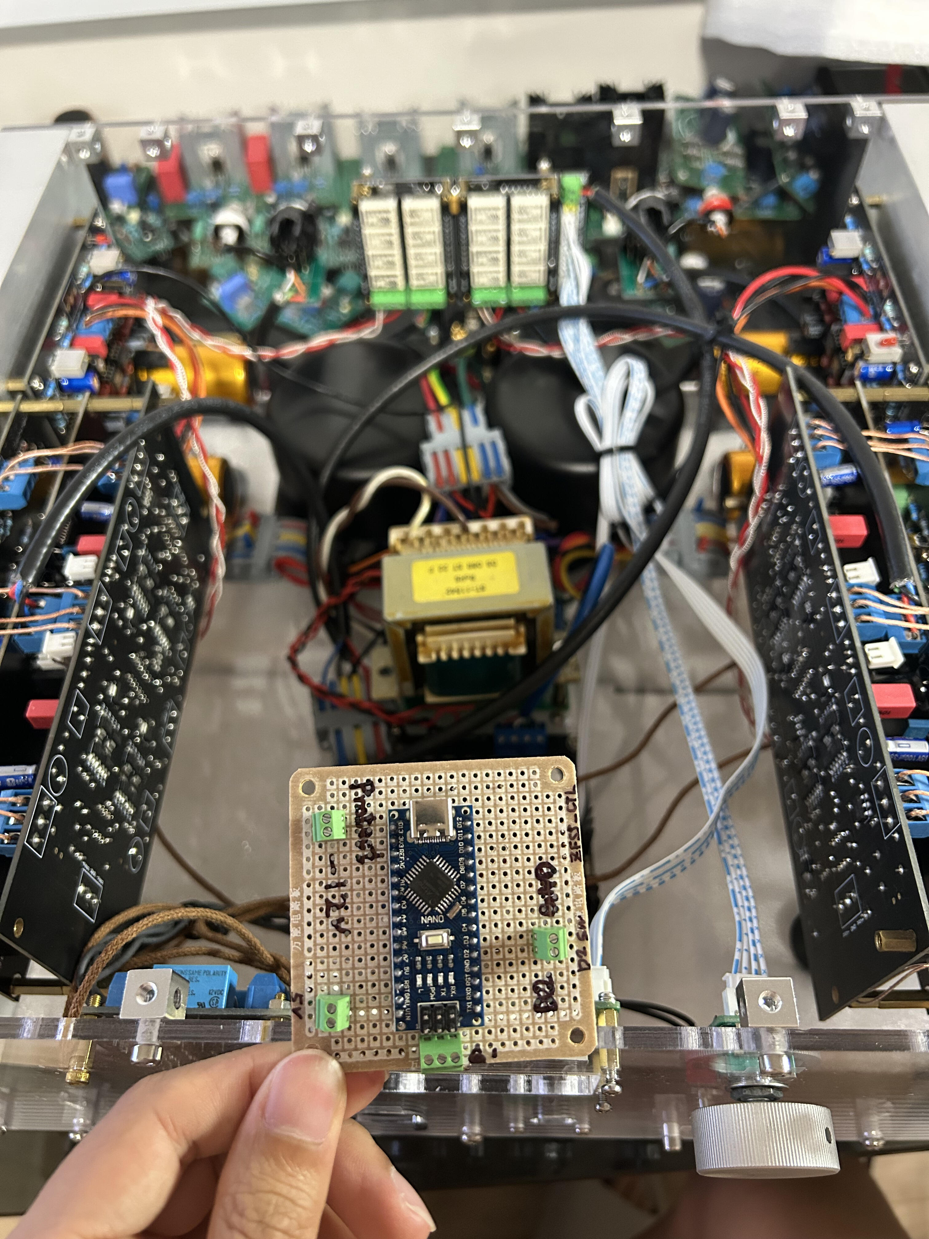
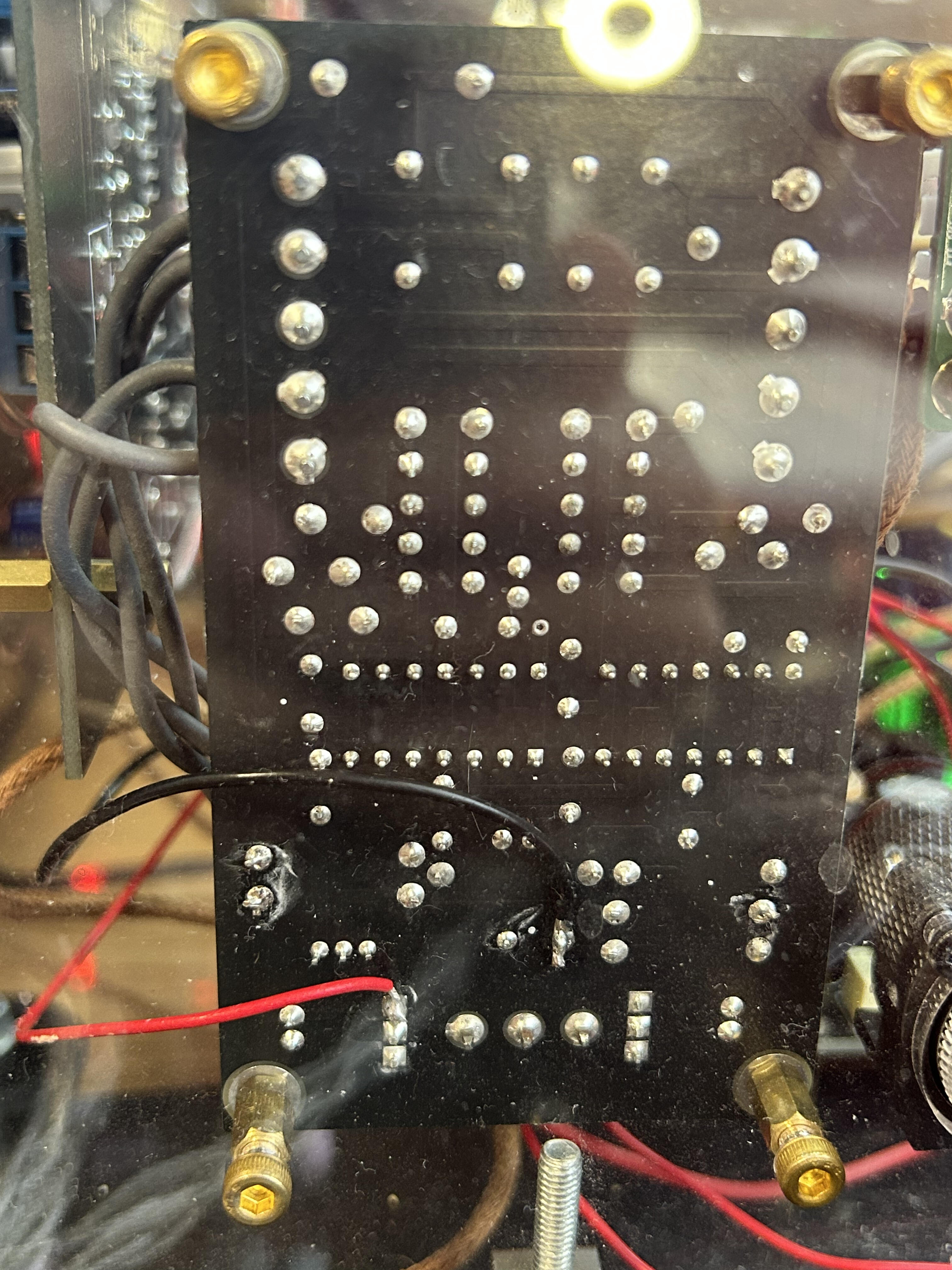
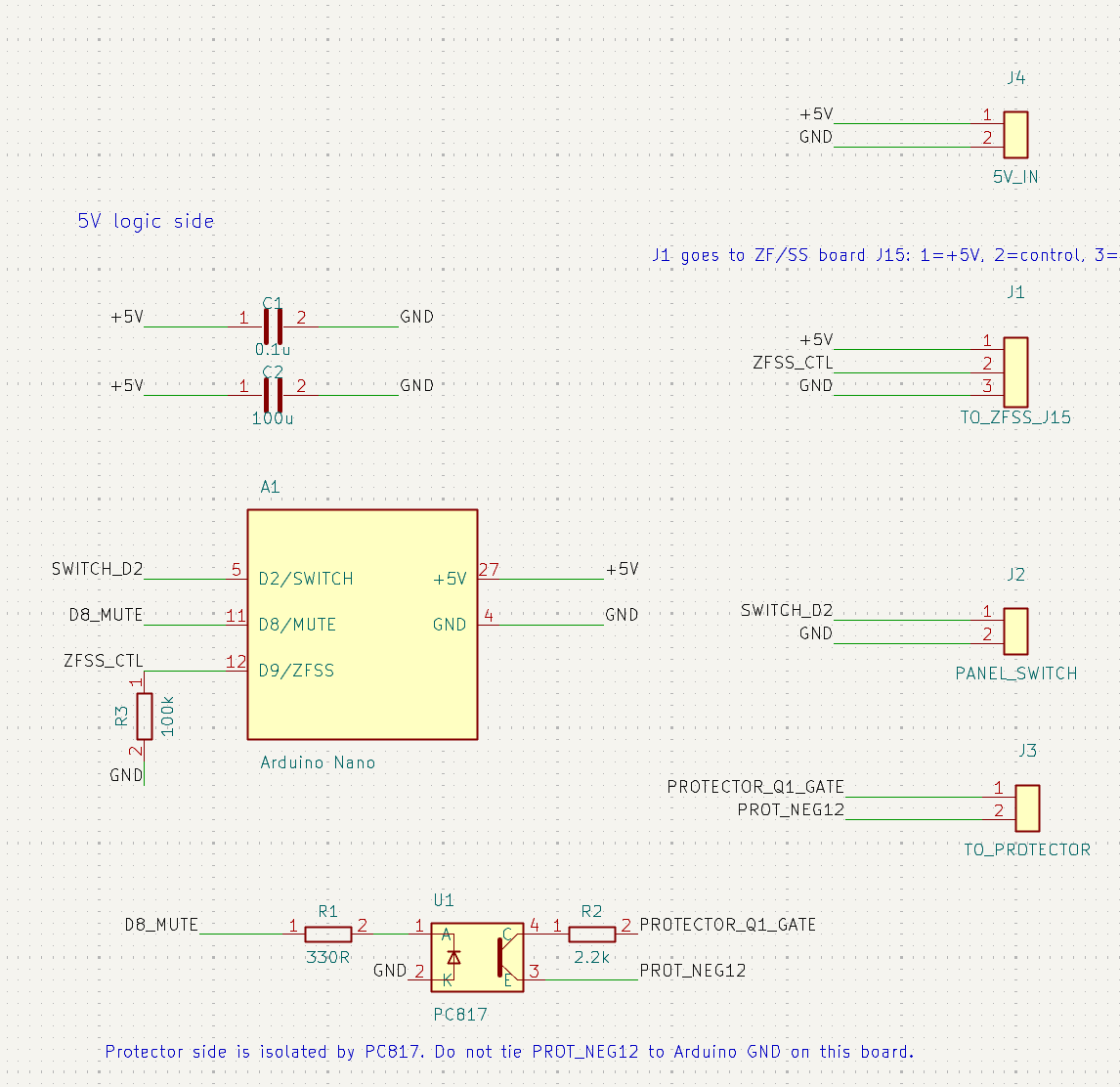
 the 470pf cap is on the power supply right? the reason for the 1 meg input caps is to give a minimum stable bias for the input stage. its expecting you to put in front of it a pot, or other much lower impedance resistor. at 50k the remaining noise is far below any possible music at that level that does not significantly lower the input impedance.Thanks, Kevin. At the moment I only had 50kΩ resistors on hand. After replacing the input resistors with 50kΩ, the background noise is almost completely gone. There's still a very slight hiss/current noise, so I may also try adding a small pF-range capacitor to ground for some additional RF filtering. I also noticed something a bit strange with my layout. On my board, installing the 470pF capacitor causes the output voltage to rise very close to the raw DC rail, whereas using a 5pF capacitor doesn't cause that behavior. I'm not sure if it's layout-related or if I've made a mistake somewhere. Has anyone else run into this issue with their build?Here are some photos of the SS/ZF switch board I have been using in my CFA3 build. The original SS/ZF switch board, designed by ang728 & vwvwbg, uses a ULN2003 as a relay driver. The mode-control input drives several ULN2003 inputs in parallel. When the control line is high, the corresponding Darlington outputs sink current through the relay coils, so the relays energize. When the control line is low, the ULN2003 outputs turn off and the relays release. The relay coils are tied to +5V, and the ULN2003 provides the low-side switching path to ground. Its COM pin is tied to +5V so the internal clamp diodes handle the relay flyback. I have been using this SS/ZF switch board for about a year and a half without any reliability issues. The only thing I noticed is that switching modes produces a small pop. Even with headphones on it has been acceptable, but recently I started wondering whether this could be improved. . So I added a small Arduino Nano interlock board in front of the existing SS/ZF control input. The Arduino reads the front-panel SS/ZF switch and outputs the required mode-control voltage to the existing ULN2003 relay board. The sequencing is: 1. Detect SS/ZF switch change. 2. Assert mute. 3. Wait briefly. 4. Change the SS/ZF relay control output. 5. Wait for the circuit to settle. 6. Release mute. The mute control is done through a PC817 optocoupler. On the Arduino side, one digital output drives the PC817 LED. On the protector-board side, the PC817 transistor pulls the existing protector MOSFET gate node toward the protector board’s -12V rail. This mimics a fault condition and forces the headphone output protection relay to open during the SS/ZF transition. So the Arduino does not touch the audio signal path. It only sequences the existing relay-control line and temporarily forces the existing KG protector circuit into mute during mode switching. In the installed photo: The top connector goes to the front-panel switch. The switch controls whether Arduino D2 is grounded or left open. The middle-right connector outputs the mode-control signal to my SS/ZF switch PCB. This is the 0V / control / +5V connection. The lower-left connector goes to the KG protector board: one wire to the 2N7000 gate node, and one wire to the -12V output of the 7912 regulator. The lower-right connector is the 5V / 0V power input for the Arduino interlock board. Arduino code attached below: const int SWITCH_PIN = 2; const int MUTE_PIN = 8; const int MODE_PIN = 9; const bool MODE_INVERT = true; // if SS/ZF mode inverted const unsigned long MUTE_BEFORE_SWITCH_MS = 250; const unsigned long SETTLE_AFTER_SWITCH_MS = 700; const unsigned long POWER_ON_MUTE_MS = 1500; const unsigned long DEBOUNCE_MS = 50; bool currentMode; bool readMode() { bool sw = digitalRead(SWITCH_PIN); // HIGH = open, LOW = grounded bool mode = sw; if (MODE_INVERT) mode = !mode; return mode; } void forceMute(bool on) { digitalWrite(MUTE_PIN, on ? HIGH : LOW); } void setMode(bool mode) { digitalWrite(MODE_PIN, mode ? HIGH : LOW); } void setup() { pinMode(SWITCH_PIN, INPUT_PULLUP); pinMode(MUTE_PIN, OUTPUT); pinMode(MODE_PIN, OUTPUT); forceMute(true); delay(100); currentMode = readMode(); setMode(currentMode); delay(POWER_ON_MUTE_MS); forceMute(false); } void loop() { bool newMode = readMode(); if (newMode != currentMode) { delay(DEBOUNCE_MS); newMode = readMode(); if (newMode != currentMode) { forceMute(true); delay(MUTE_BEFORE_SWITCH_MS); setMode(newMode); currentMode = newMode; delay(SETTLE_AFTER_SWITCH_MS); forceMute(false); } } }Some pics: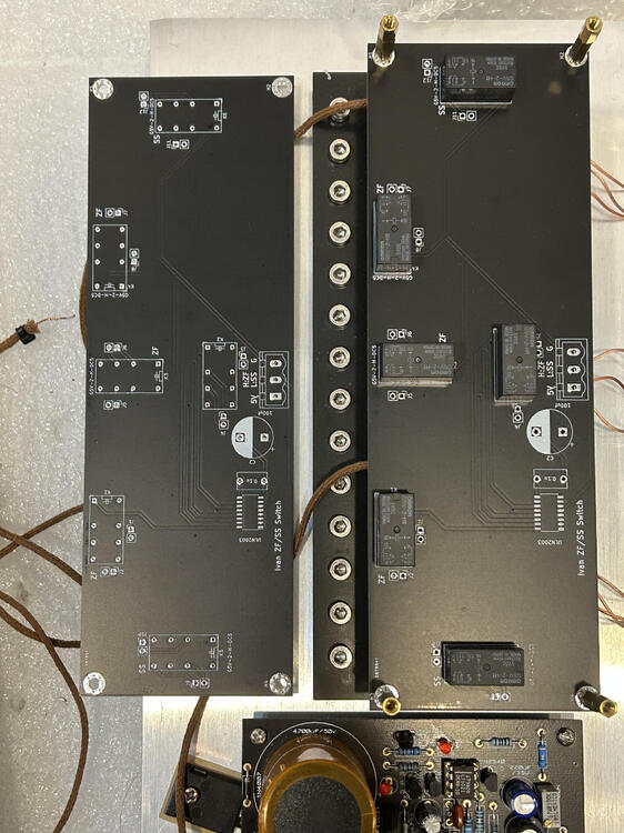
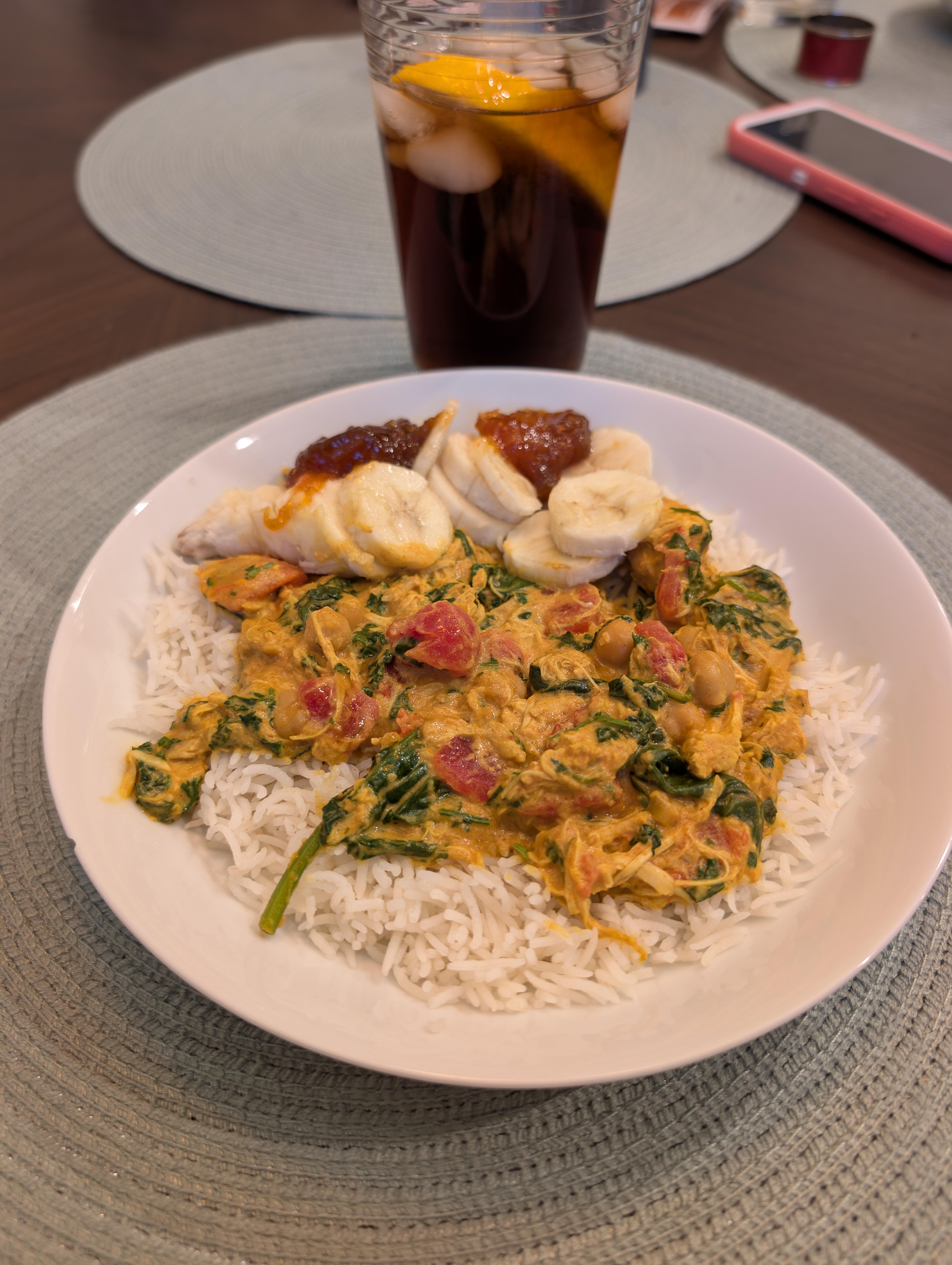
 🐓🍛 4 BDF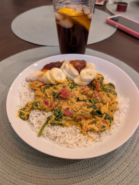
- Last week
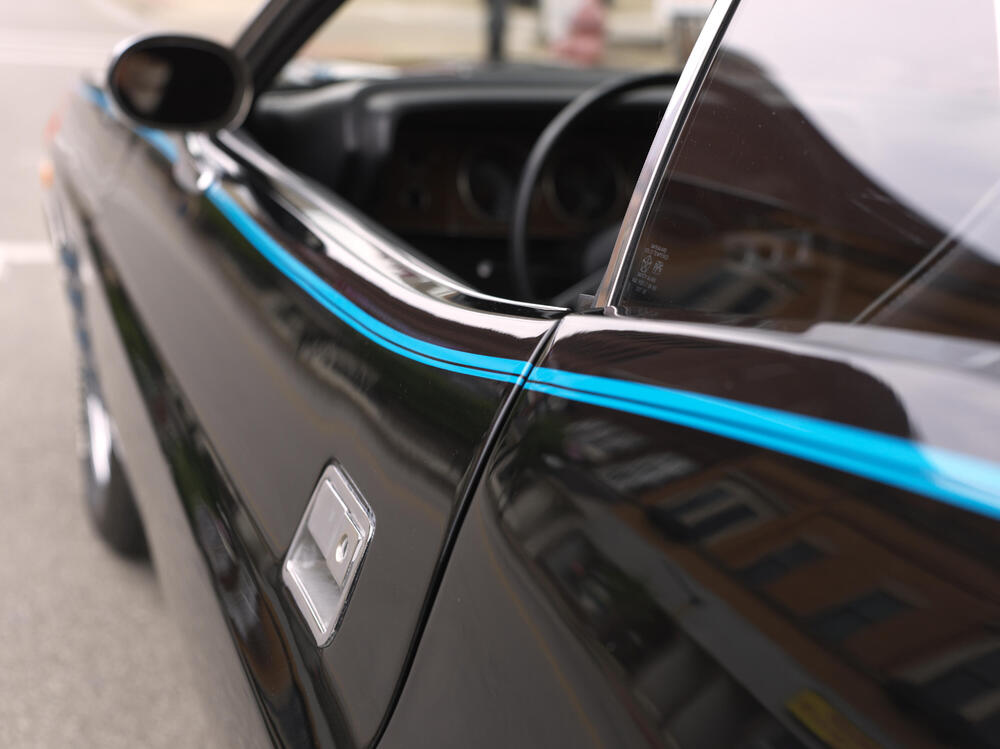
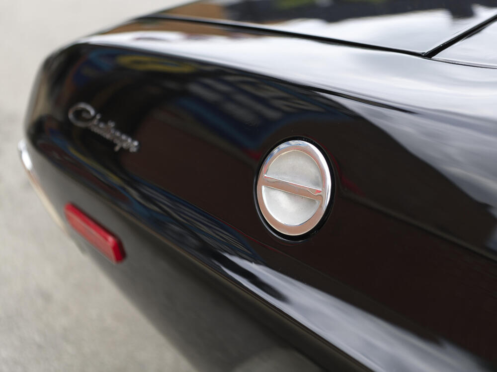
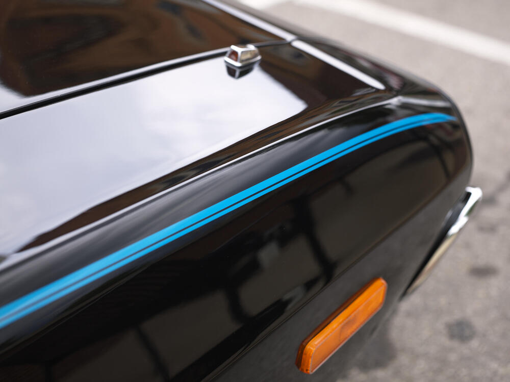
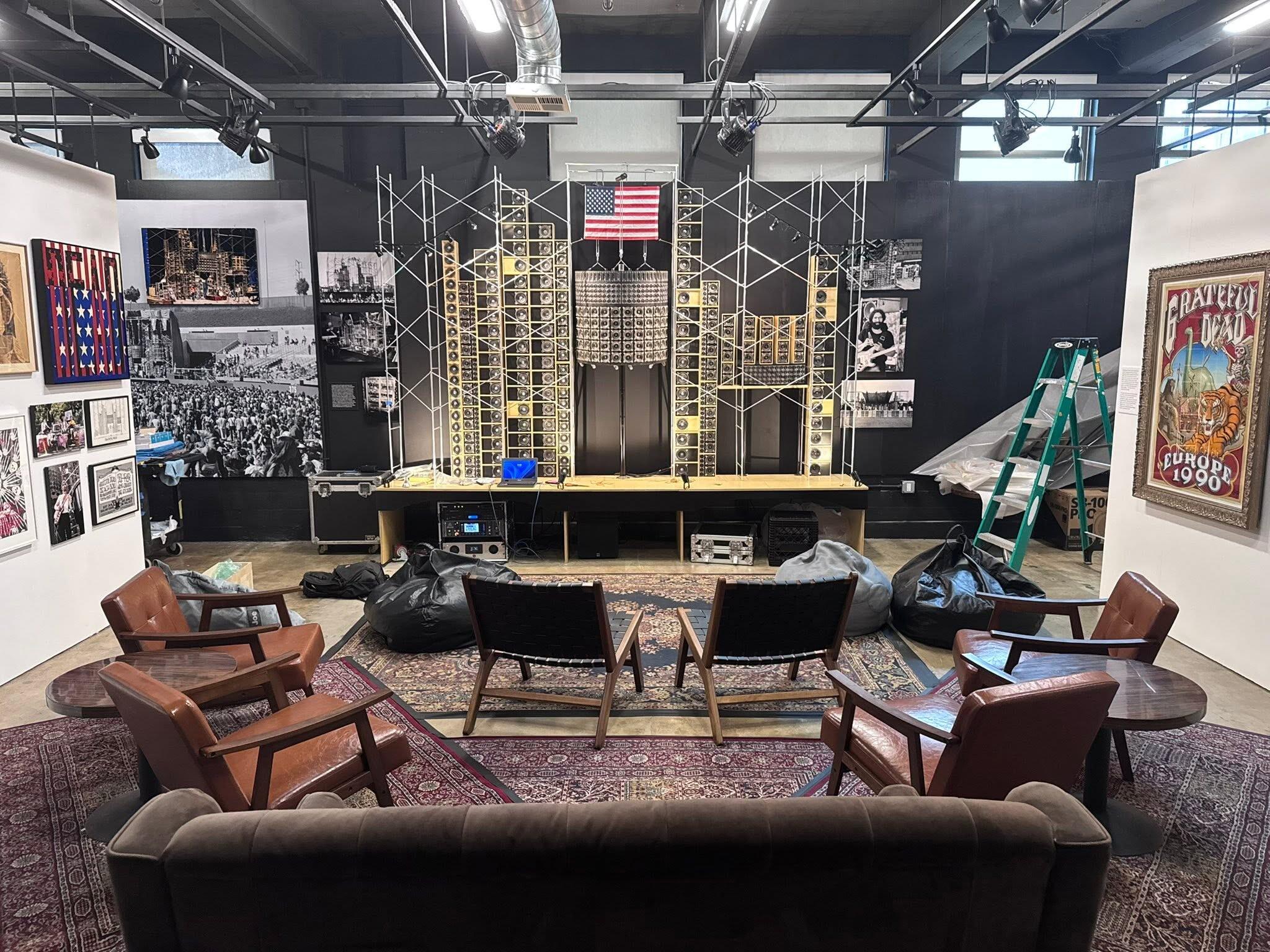
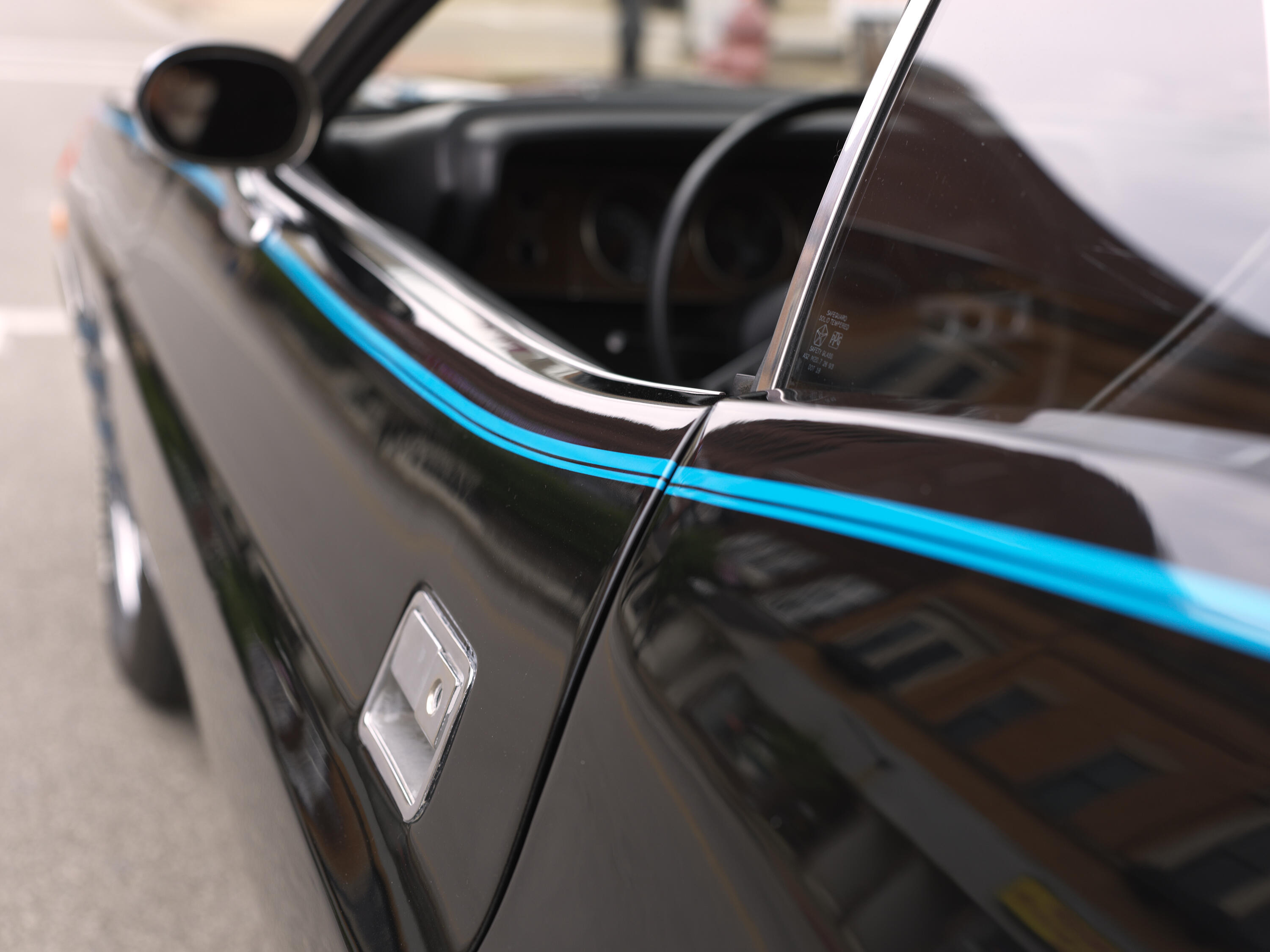
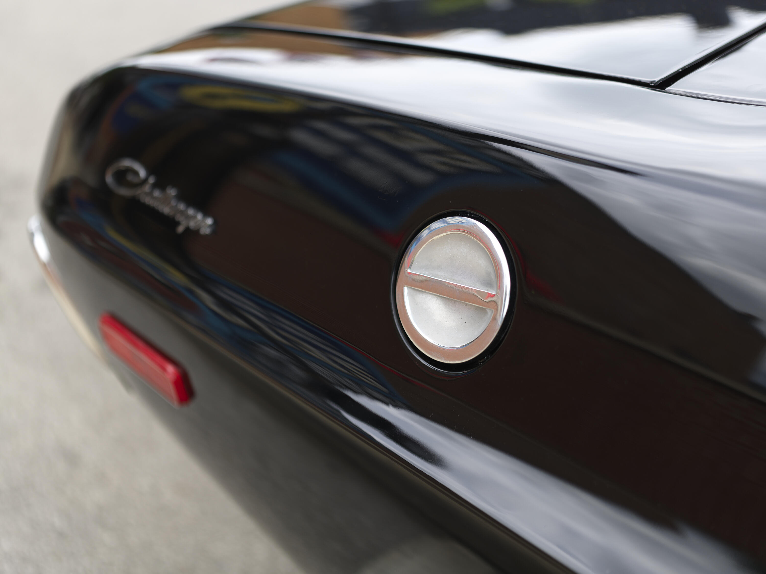
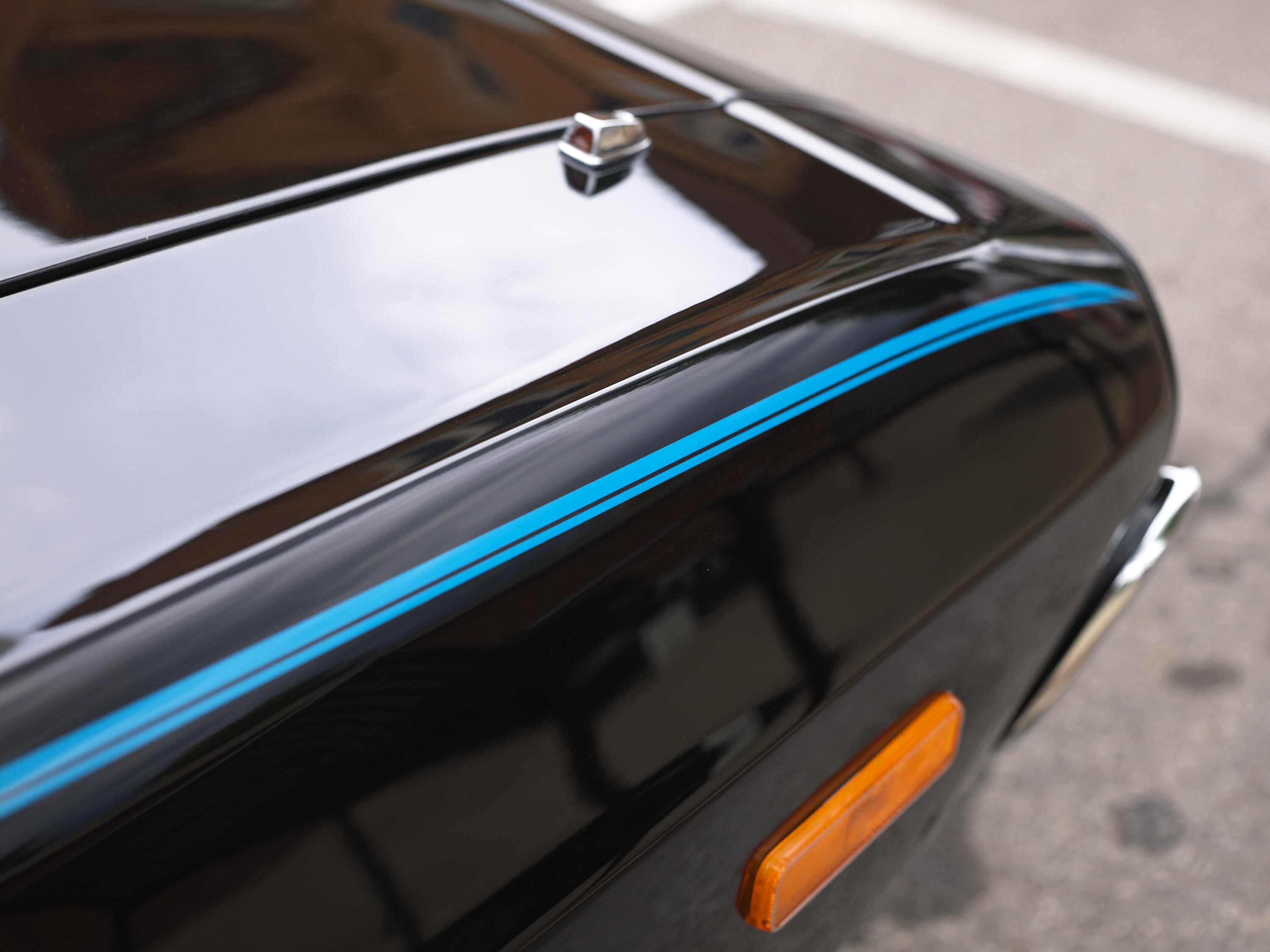
How about speaker model porn? A famous 1970s live rig from some jam band or other.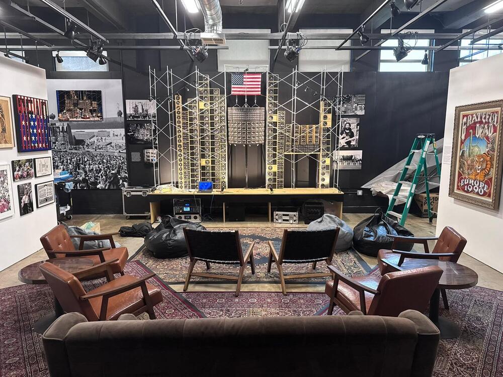 ^ Agreed and nice fall off. Visiting my dad and hit a nearby car show last weekend. And by car show I mean a car. Rain threatened the event so only a 1974 Challenger 383 Four Barrel was left when I showed hours before the scheduled end. Quick tests of the used Hassy 55v f/2.5 I recently picked up. Much to learn.
 the resistors are just there to make sure its stable with nothing plugged into it. change the input resistors to as low as possible compatible with what is going to drive it. 10k is probably what i would do.The Outlaws (Prime) - fun watch. We're through the first two seasons, looking forward the third.A small update on the Super Carbon troubleshooting. After replacing the 5pF capacitor with the 470pF value shown on the schematic, the oscillation was reduced significantly. However, there is still a very noticeable background noise. At this point I'm starting to suspect the XLR input stage instead of the power supply. When I short IN+, IN−, and GND together at the input, the background noise disappears completely. That makes me think the input stage may simply be too sensitive. @kevin gilmore do you think it would make sense to reduce R48 and R49 from 500kΩ to something like 200kΩ or 100kΩ? Or perhaps add a small capacitor for some RF filtering at the input? I'd appreciate any suggestions before I start experimenting further.Condolences and ... just yeezh, that just sucks of a situation.Condolences Brent and family. RIP Bones.Thanks everyone for the kind words and thoughts. Talked to my brother today. Turns out he (Bones) didn't have life insurance, nor any preplanned funeral arrangements. Turns out it's going to be 4500$ to have him cremated, and none of us are able to swing it. This sucks, because it's just putting more and more stress on my mom. I can't even fly back to be with her right now since hurt my back a month ago and can barely walk some days, much less travel across the country. Glad I was able to go out a few months ago, but hate I can't be there now.I am working on a CFA3 build where the original THAT340 input devices have been changed to a JFET input pair. For a rough simulation I used these models: .model 2SJ103 PJF VTO=-1.5 BETA=10m LAMBDA=0.01 RD=20 RS=20 CGS=50p CGD=45p IS=10p .model 2SK246 NJF(Beta=2.5m Vto=-1.5 Is=1e-14 Cgd=4p Cgs=5p) This is only intended as an input-impedance / loading check, not a final device-accurate distortion simulation. With the current SS input/feedback network: R24/R26 = 5k R44/R49 = 50k C9/C10 = 20p I get approximately: SS mode input impedance: ~11.7k ohm per phase at 1 kHz ZF mode input impedance: ~50k ohm per phase at 1 kHz So even though the input devices are JFETs, the SS mode input impedance is still relatively low because of the surrounding SS input/feedback network. The practical concern is that I changed the volume control from 10k to 50k. With a 50k attenuator, the source impedance around mid attenuation can be much higher than with a 10k control. That seems like it can load/interact with the ~11.7k SS-mode input impedance, while ZF mode is much less affected. I am considering scaling the SS input/feedback network values upward while keeping the same approximate ratio and compensation time constant. Current: R24/R26 = 5k R44/R49 = 50k C9/C10 = 20p Conservative option: R24/R26 = 10k R44/R49 = 100k C9/C10 = 10p Simulation: SS input impedance rises to ~20.2k per phase SS gain changes from about 15.0 dB to 14.7 dB More aggressive option: R24/R26 = 15k R44/R49 = 150k C9/C10 = 6.8p Simulation: SS input impedance rises to ~26.6k per phase SS gain changes to about 14.5 dB The idea is to reduce the current drawn from the volume control and raise the effective SS-mode input impedance, without changing the low-frequency feedback/input ratio too much. Has anyone tried this on a JFET-input CFA3, especially with a 50k volume control? Does scaling R24/R26 and R44/R49 like this seem reasonable, or is there a known preferred value set for JFET-input builds?


























Important Information
By using this site, you agree to our Terms of Use.