All Activity
- Past hour
-

The Knuckledragger 3rd Memorial Slow Forum Post
Knuckledragger replied to Knuckledragger's topic in Off Topic
Oh boy. New OL post. Yes, I am going to repost all of them here. -

Megatron Electrostatic Headphone Amplifier
JoaMat replied to kevin gilmore's topic in Do It Yourself
Thanks for your comments, @simmconn. The heatsink gets warm and user is aware of it. I think he is running at 400V/22mA and so far, it seems to work. If it gets too hot than he can’t use this thing - that’s life. For pin dimension. The first version used Neutrik XLR3 pins. They were perfect, diameter slightly undersized. But to short to be soldered direct to main PCB. When looking for brass rod the best I found was 2.5 mm so, I decided to try that. 2.5 mm works with my Teflon tube sockets. The user is informed of that pins are soldered only on one side and if pins come loose, we have to find a better solution or perhaps abandon this thing. I use Addnorth HT-PLA Pro filament. Better heat performance than PLA but not as good as ABS. I’m confident the socket isn’t a problem. It might be a problem with the transistor tab cover. I haven’t thought about the cover until your post - thank you simmconn. Now the user is informed, and he promised to keep an eye on the cover. - Today
-
 Zetian77 joined the community
 -
I don’t think the non-grata is an issue. It’s just that improving from a Benchmark isn’t easy and most of us haven’t been into audio much lately, or at least enough to offer any insight worth reading.
-
 Unholy carp, it's Ren, doing a different song than "Hi Ren", and well!
 -
About the pin choice. I think this one might be closer to the original tube pins: MPN:6835-0-00-15-00-00-44-0 https://www.mouser.com/datasheet/2/273/MMMC_S_A0004813843_1-2556643.pdf I haven’t ordered it yet to confirm, but maybe it helps you. Also, I’d like to get your advice: At 400 V / 22 mA, would you consider setting Vgk around –95 V a good operating point? I’m also thinking about increasing the static current to around 27–30 mA. From what I see, the EL34 max plate dissipation is ~25 W. At 400 V / 30 mA, that’s only about 12 W, so it looks safe on paper. I’d love to hear your thoughts on this.
-
I'm persona non grata. Guess I'll stick with with the DAC1.
-
I didn't watch it, but I imagine they're speaking truth.
-
This one is for the fathead.
- Yesterday
-

Megatron Electrostatic Headphone Amplifier
simmconn replied to kevin gilmore's topic in Do It Yourself
Interesting design! I’d be a bit worried about the thermal and mechanical side of things. The thermal resistance of the heatsink this size is probably going to run above 5C/W without forced air flow. It is going to run too hot to touch at 350V to 400V/20mA (7 to 8W). With 3C/W theta JC on the 10M90S, there is still margin on the die temperature. If I were to design a PCB to be plugged into a tube socket with soldered pins, I’d use slightly undersized pins and whatever copper I can get for adhesion to the board (double layered board with plated-thought holes in 2-mm or thicker PCB), especially if the counterpart is the unforgiving “modern” tube sockets with tulip type spring contacts. Last but not least, when the whole thing gets very warm, I’d use materials with higher working temperature such as ASA or ABS. PLA is probably not going to last very long. -
Your presence there is not going unnoticed.

-
Ye Macce Threade
Knuckledragger replied to Hopstretch's topic in GoRedwings19's Computer Help Hotline
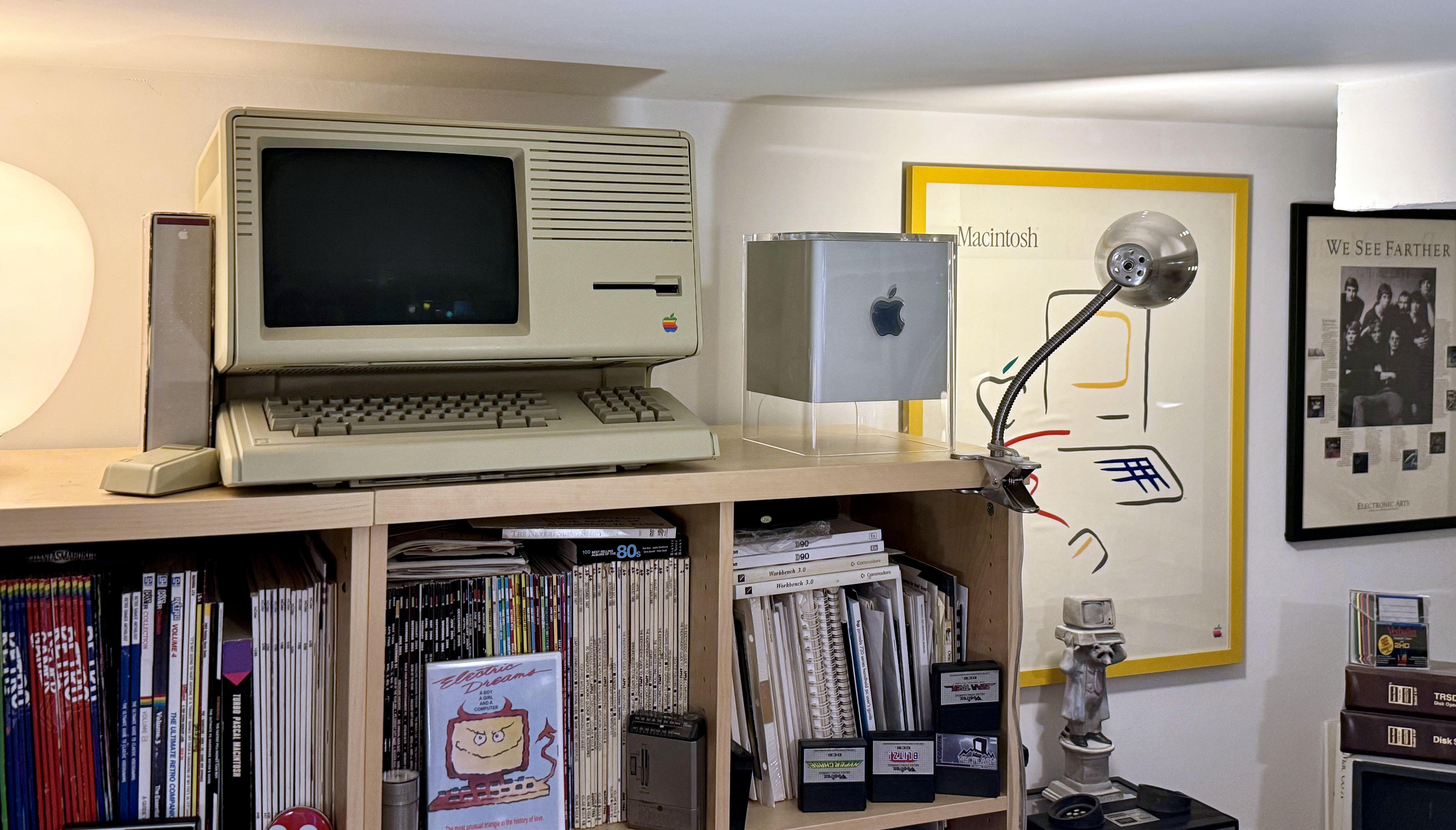
That's wild, as it uses a white Apple logo some 15 years before it became the company standard. -
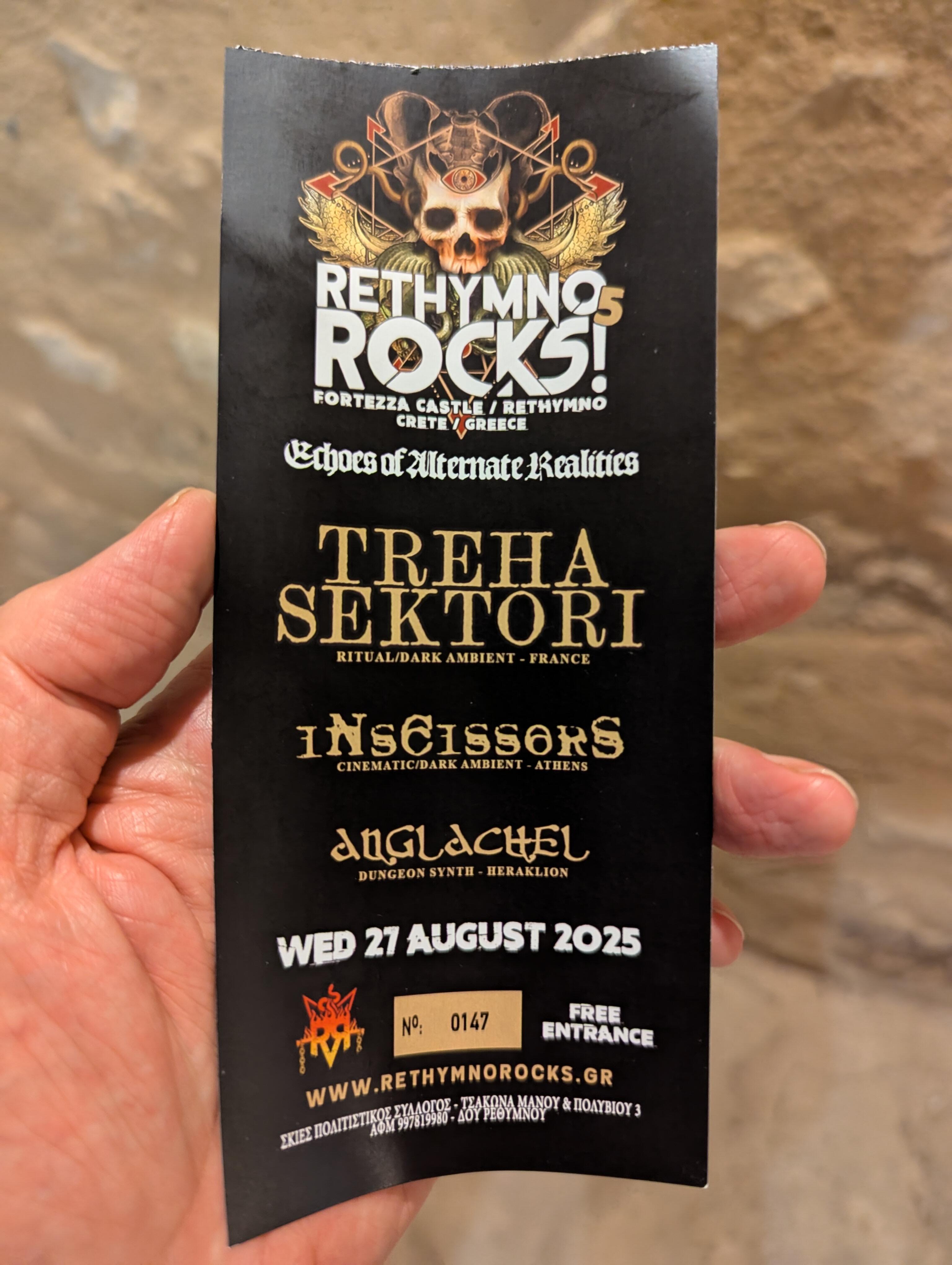
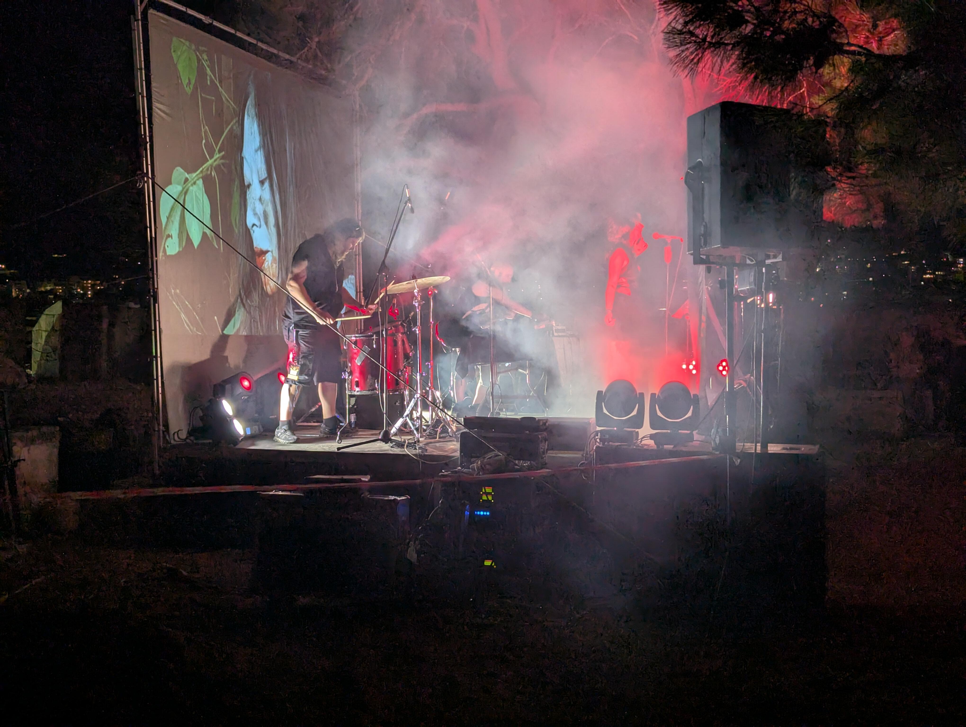
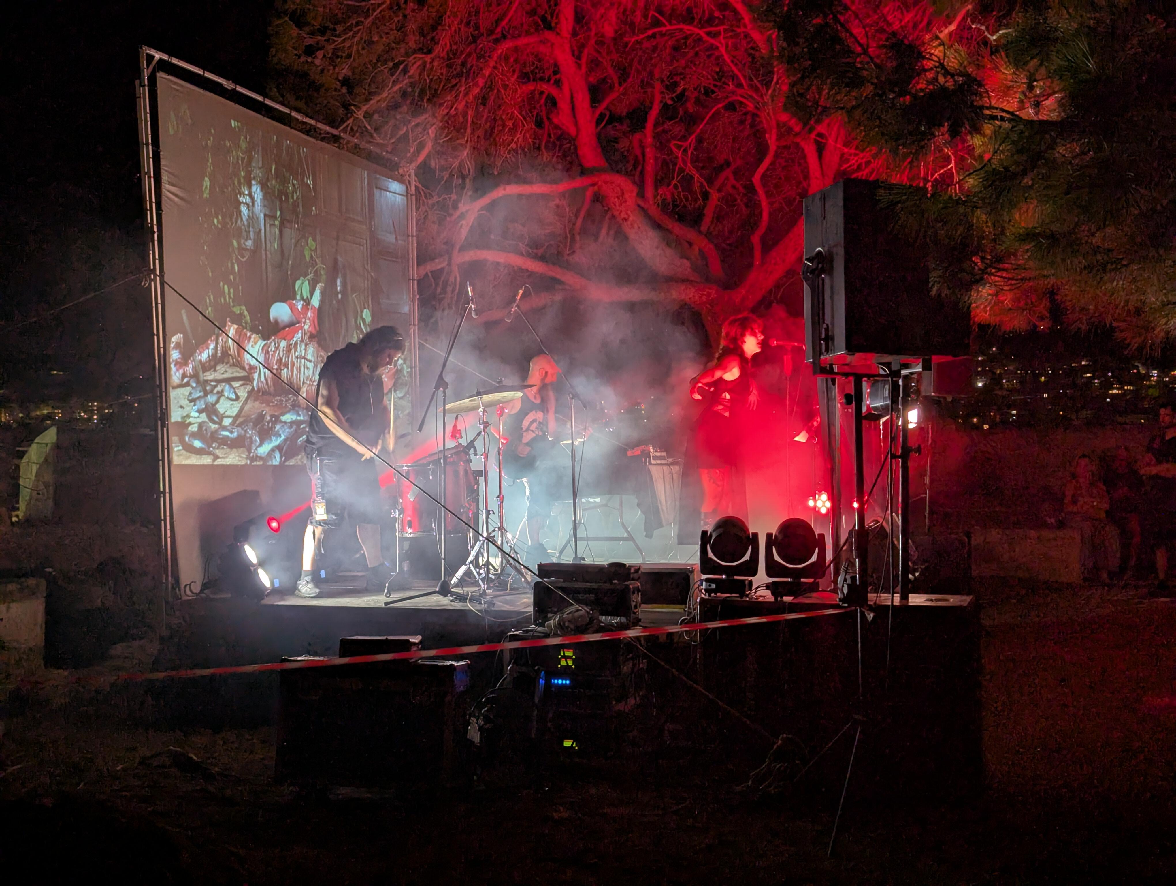
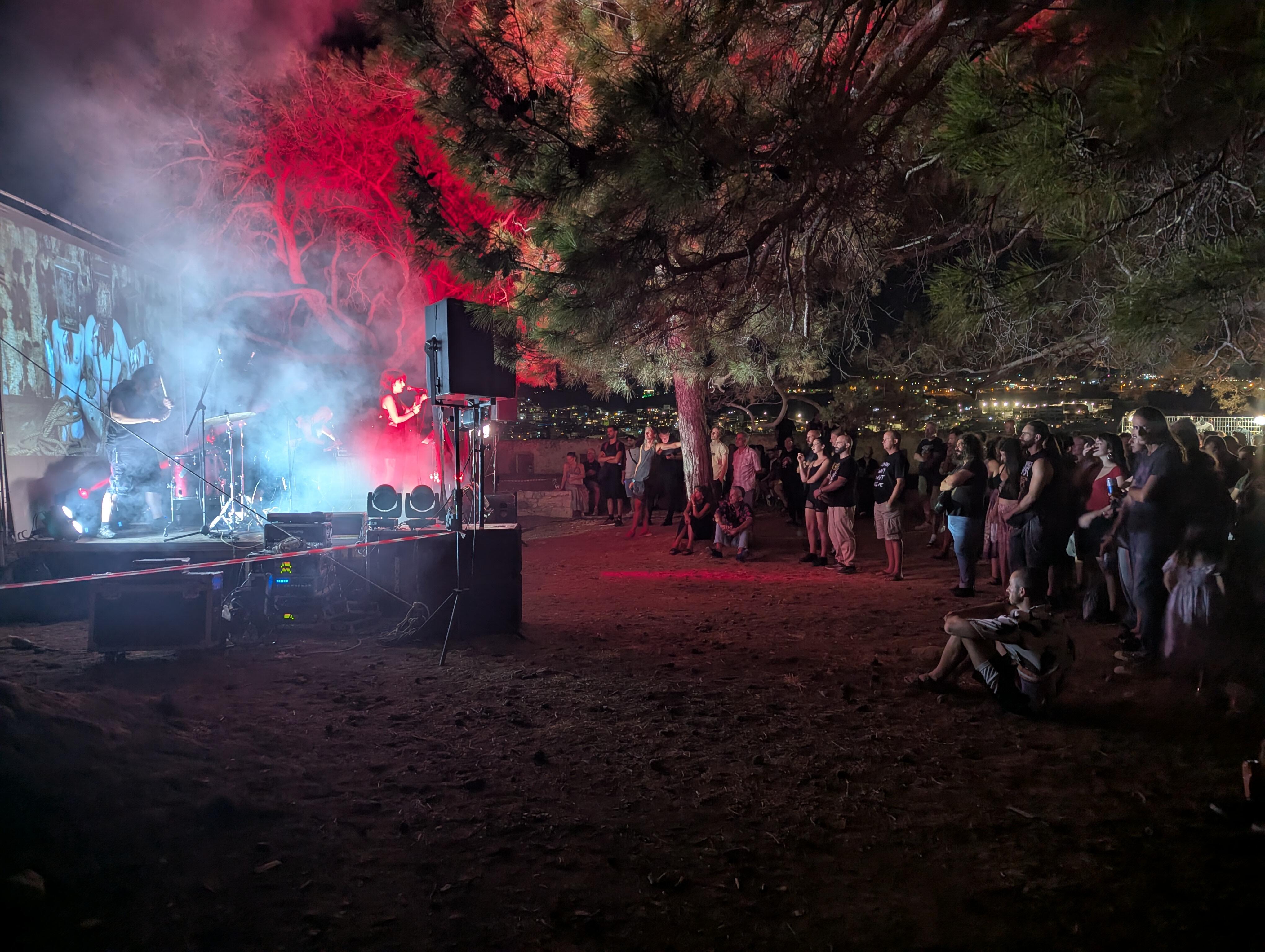
We weren't expecting this. But we got to sample the dark ambient of inscissors
-
^^Yup.
-
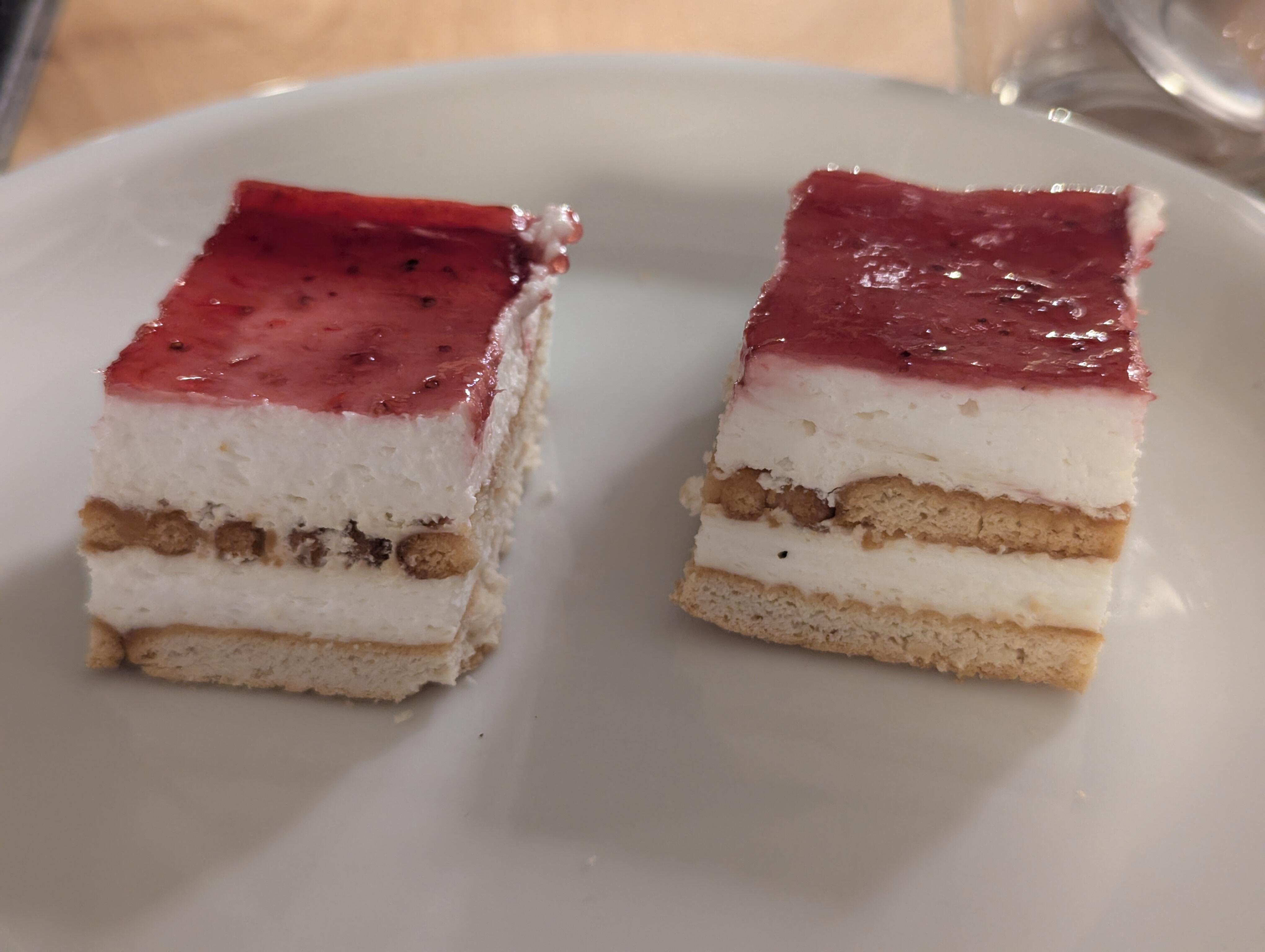
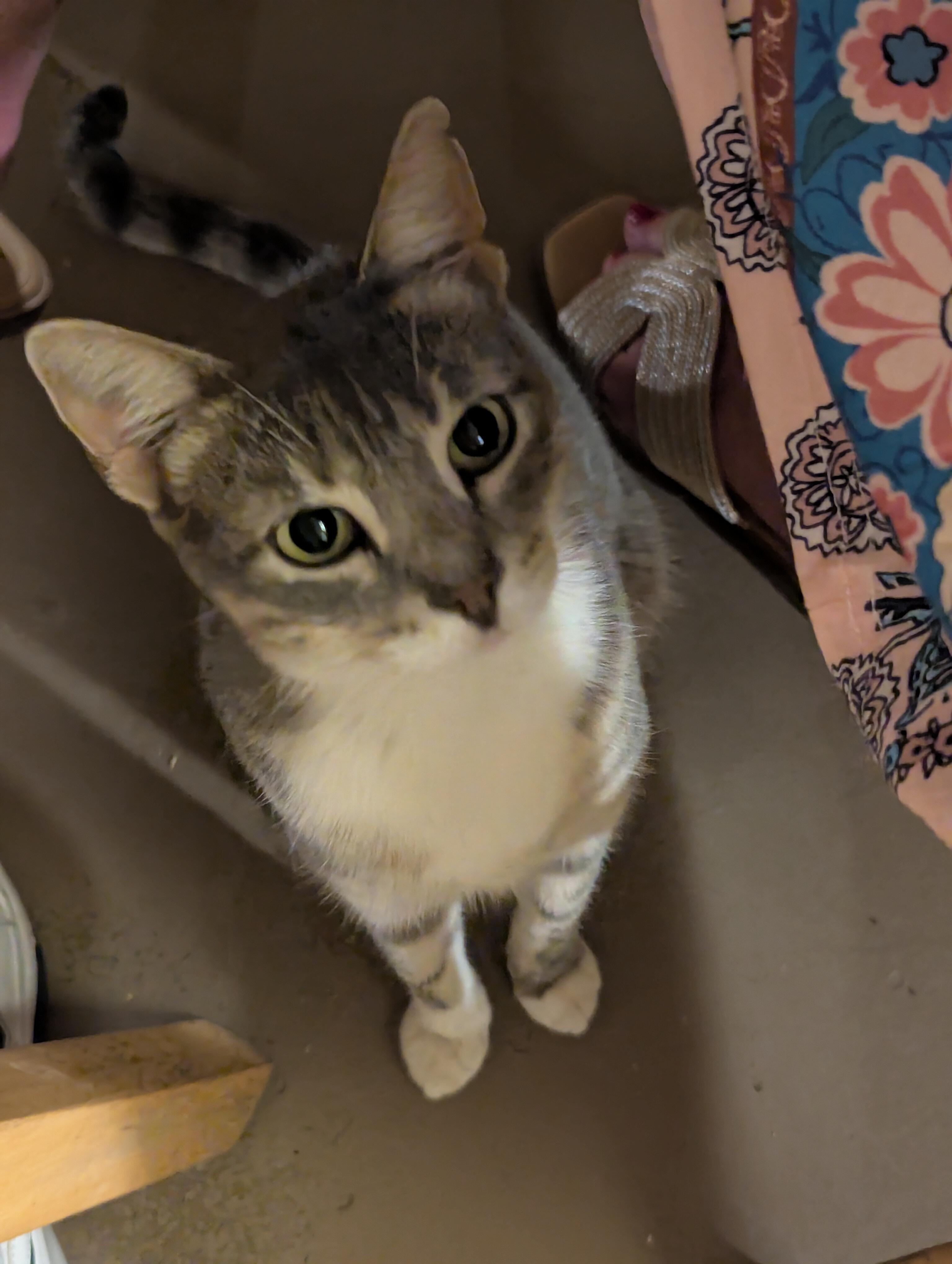
I like the idea of dessert on the house. As do the local cats
-
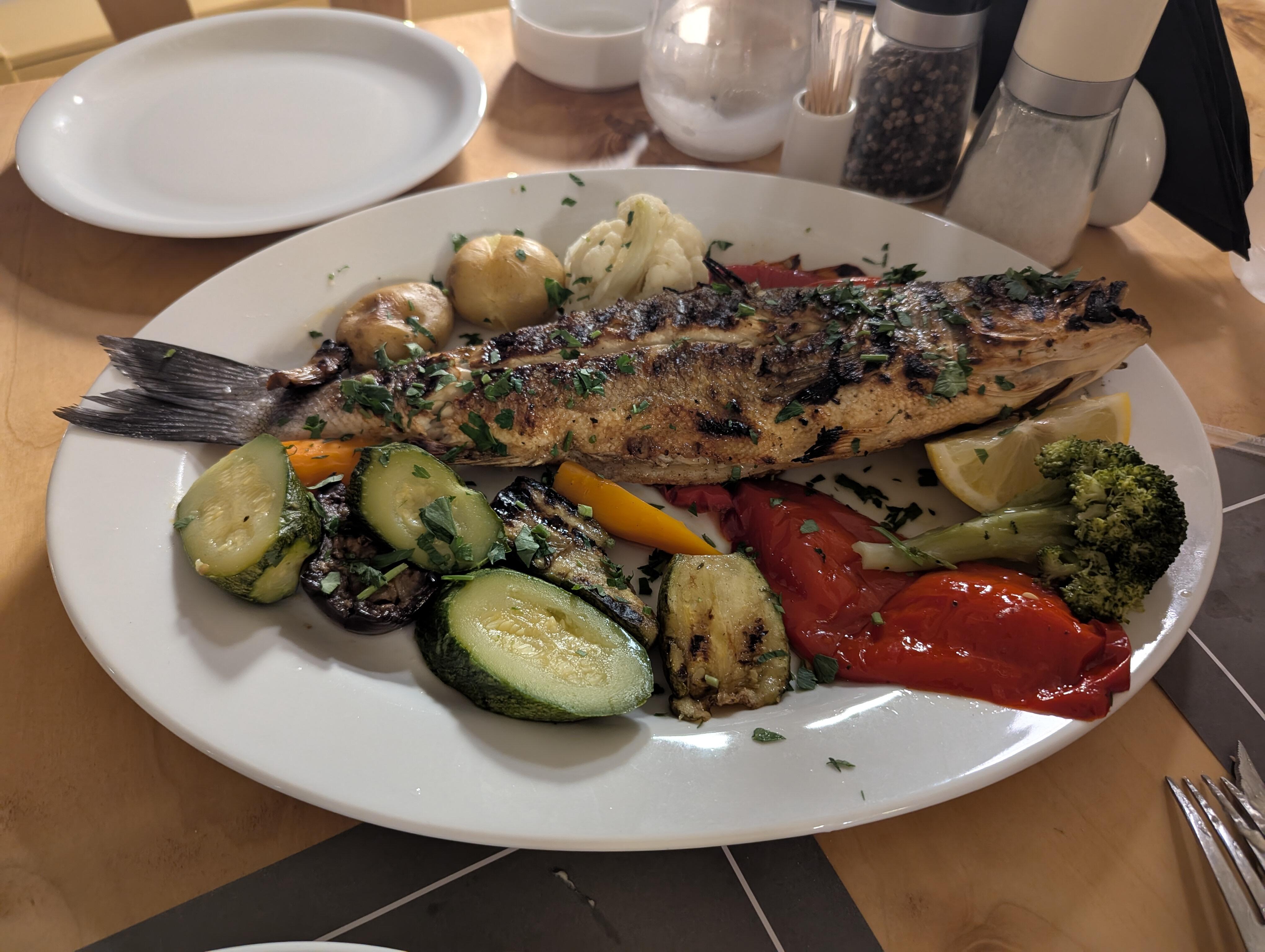
Fresh Fish
-
It might be a binder of Apple printed documentation for the Lisa.
-
Ye Macce Threade
Knuckledragger replied to Hopstretch's topic in GoRedwings19's Computer Help Hotline
Via Flickr, two fun bits of history: Edit: Anyone know what is that rectangular thing to the left of the Lisa? Behind the "bar of soap" mouse. I think it might be a software box.
-
Family started chipping in so I'm now over the 75% threshold. Just a little bit more to go.
-
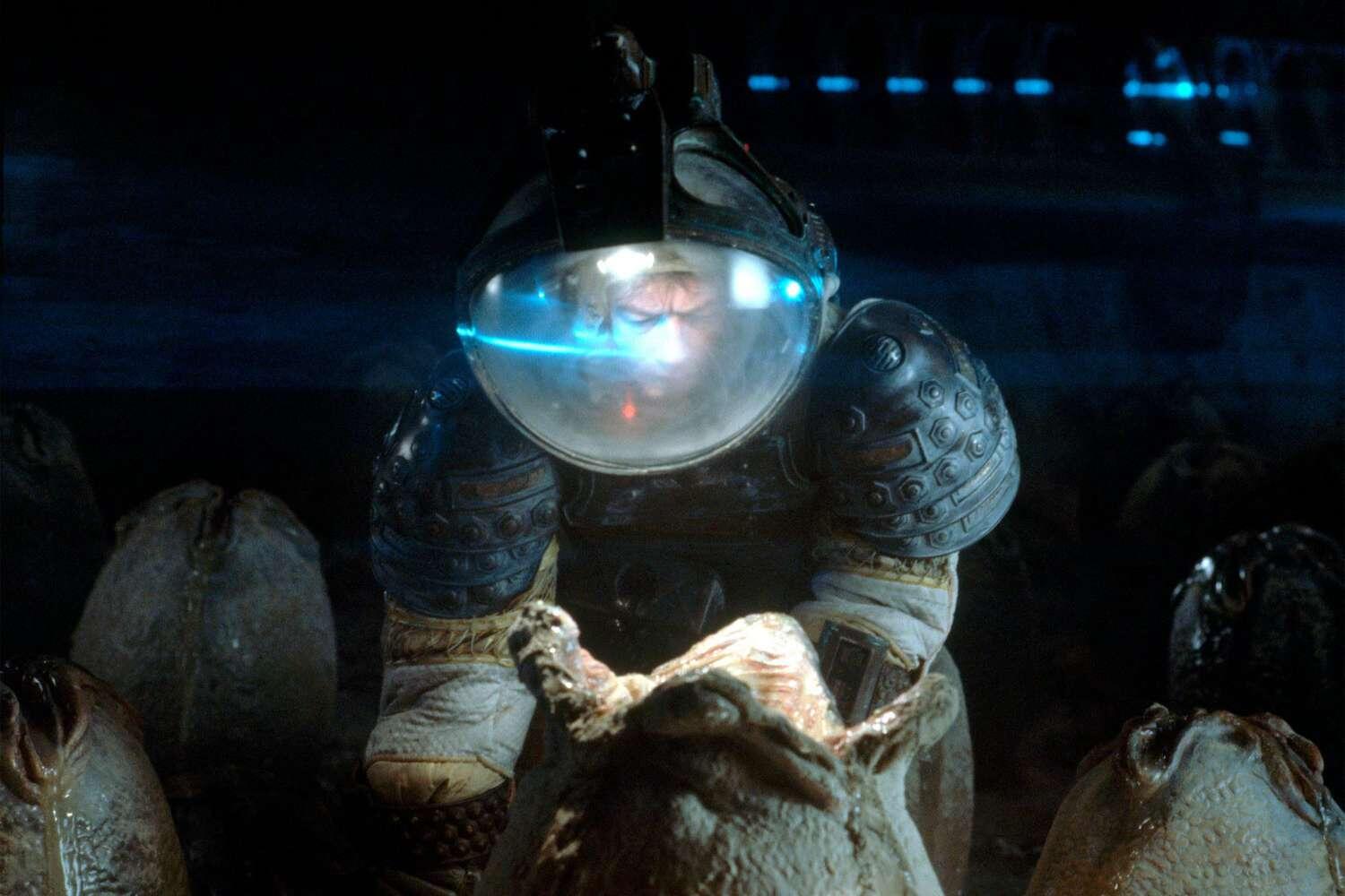
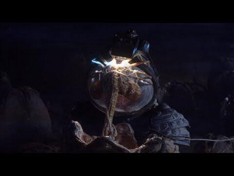
Apparently you've never watched the Alien movies.
-
Well that's reassuring. /s
-
Megatron Electrostatic Headphone Amplifier
JoaMat replied to kevin gilmore's topic in Do It Yourself
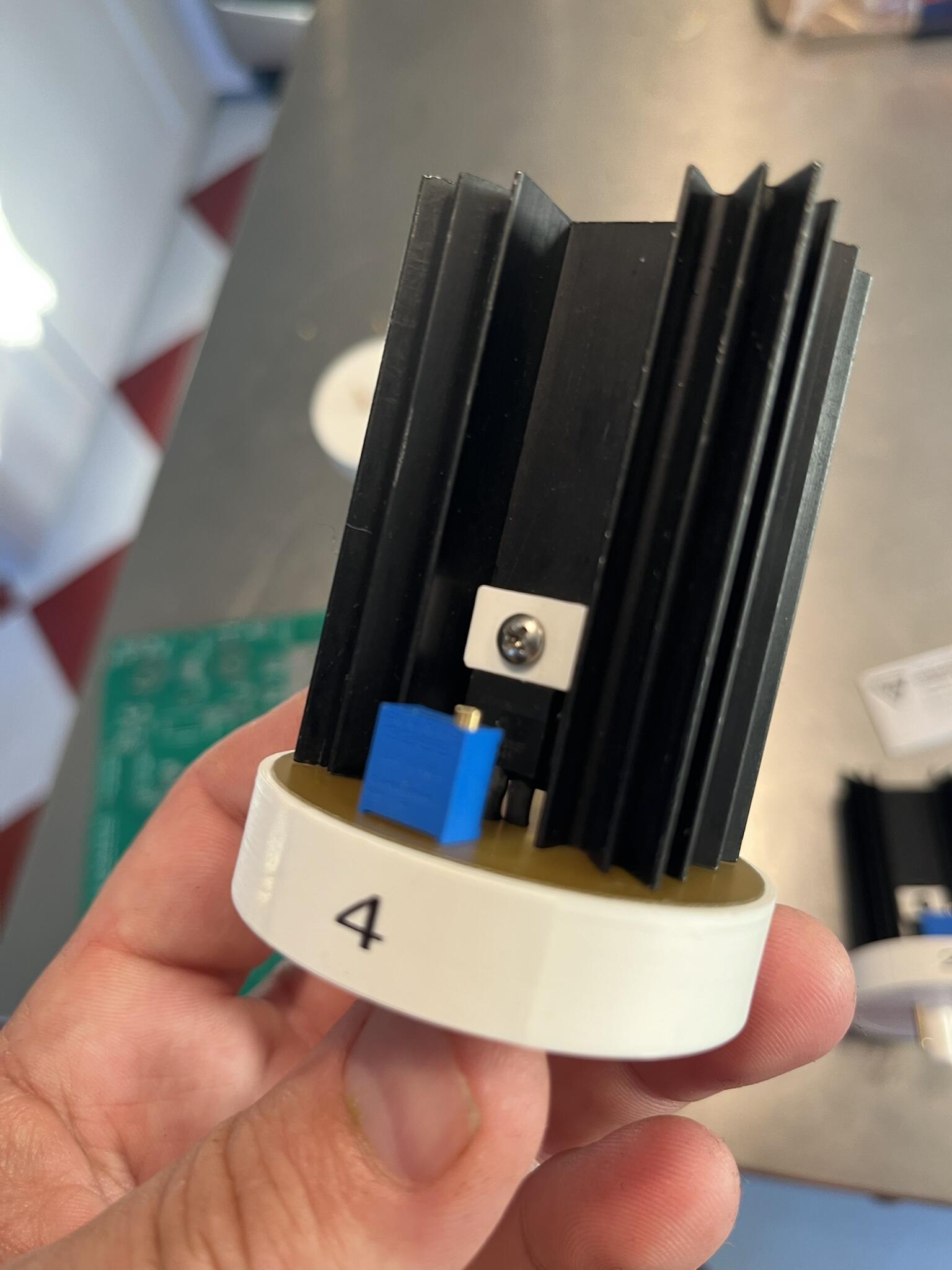
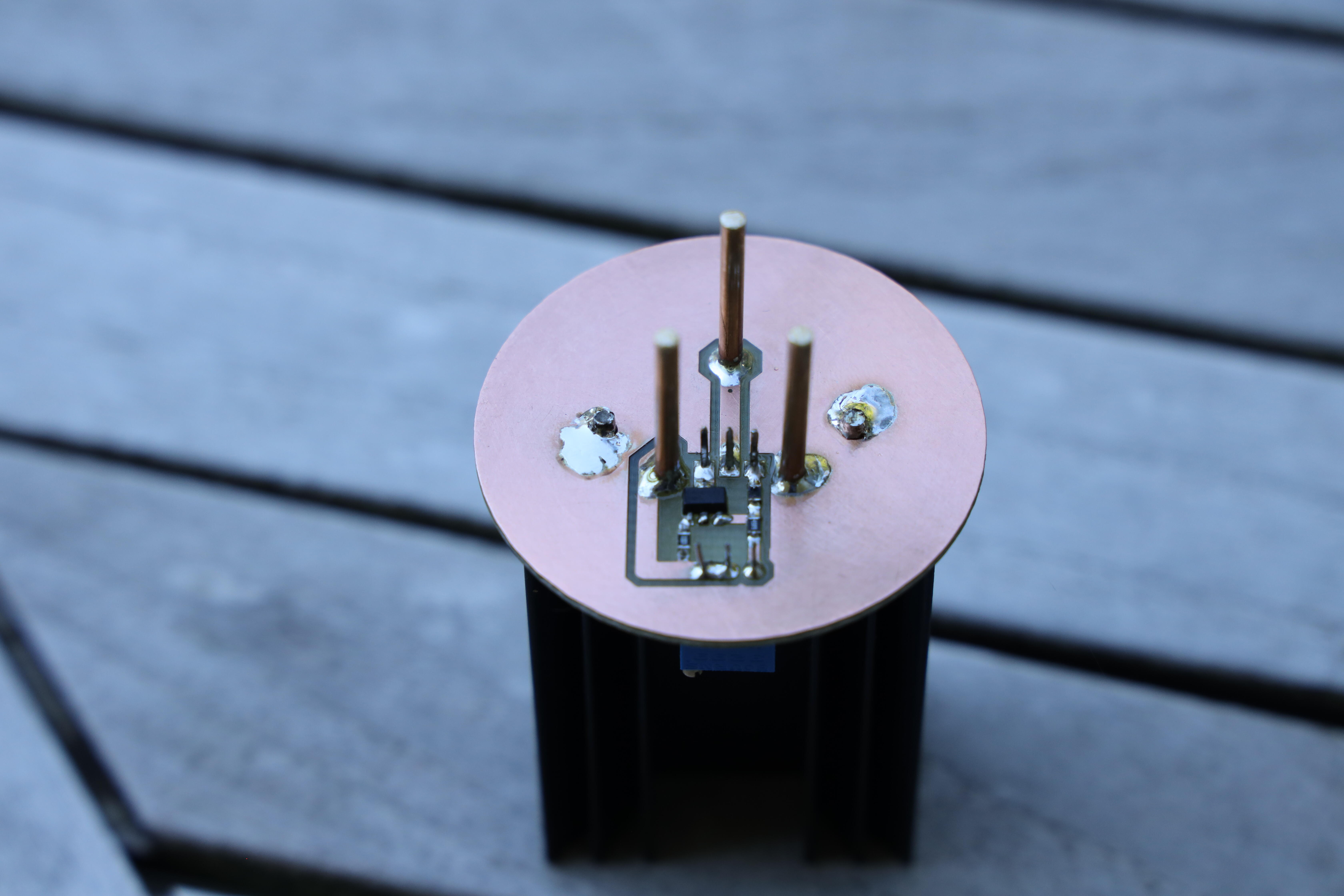
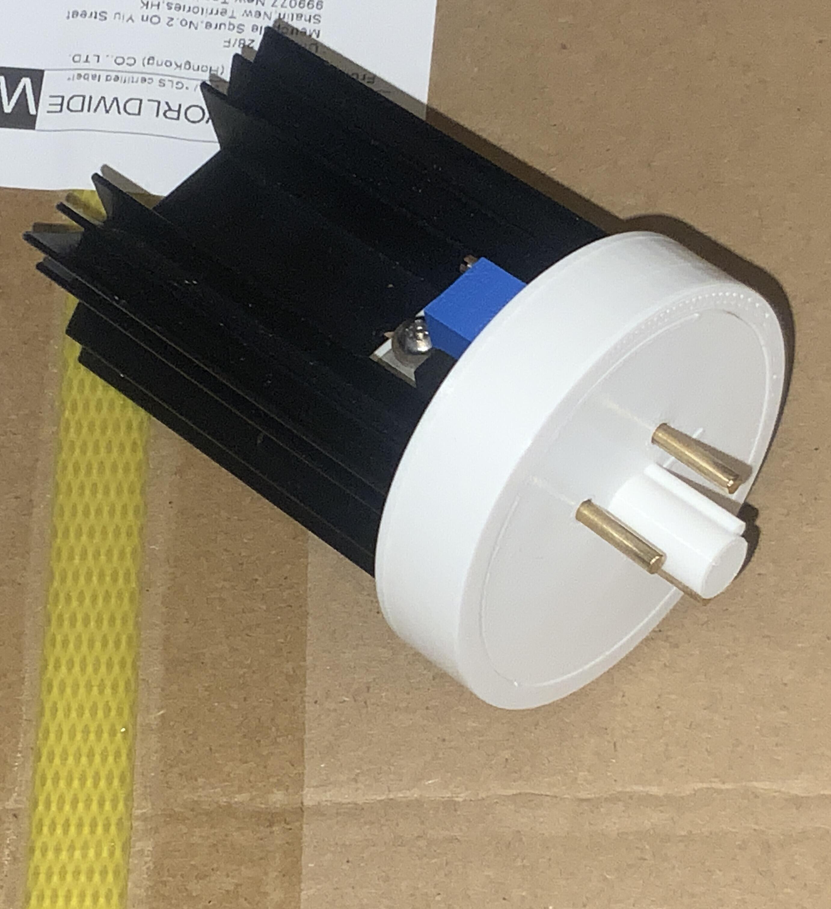
New solid state CCS for Megatron. Now with a third pin for ground. The pins are made from 2.5 mm brass rod, which is almost 0.10 mm thicker than tube pins. PCB is a CNC milled one side 1.5 mm copper clad. So, no copper on top side of PCB. Holes for the three pins are 1.0 mm deep and you have 0.5 mm epoxy laminates left. Transistor pins are protected with heat shrink tube and the exposed metal tab is protected with a 3D printed cover. The screw holding transistor to heat sink is electrical connected to it and to the ground pin. The white base with guide pin is made of three 3D printed parts.
-
First human case of flesh-eating screwworm parasite confirmed in US https://www.theguardian.com/us-news/2025/aug/25/new-world-screwworm-flesh-eating-parasite-case-us?CMP=share_btn_url
-
That seems really unlikely. If something that wants to kill you is already inside your body, I'd think it would just burrow in further.
-
Here are the links that my brother recommended: The League of American Bikers: https://bikeleague.org/#null https://bikeleague.org/ridesmart/ridesmartvideos California Bicycle Coalition: https://www.calbike.org I like blessingx's suggestion of a horn. I have a bell on my e-mtb bike. I also suggest both a front and rear lights to make yourself more visible when not in a group.
-
We've watched all four episodes and it's fun. But I have some kind of bumpy rash on the back of my neck and I'm concerned something is going to pop out and kill me.