

Leaderboard
-
Voltron
High Rollers17Points34512Posts -
Aura
High Rollers11Points6885Posts -
VPI
High Rollers8Points9103Posts -
Augsburger
High Rollers7Points13165Posts


Popular Content
Showing content with the highest reputation on 08/23/16 in all areas
-
4 points
-
4 pointsDid a pressure cooker pork loin. Now eating it. Sent from my iPhone using Tapatalk4 points
-
3 pointsYou're in for a treat, Steve. We are on ep. 5 and I am considering skipping ahead because Claire and Alden are slowing me down!3 points
-
3 pointsOk, I know my amps are not very pretty , but I like the simple front. I made the 20mA versión so it need a big heatsinks3 points
-
3 points
-
3 points1 point1 pointHadn't heard of Stranger Things. Now I know what to start watching tonight. Thanks!1 point1 point1 point1 point1 pointForgot to post brunch photos from Dottie's True Blue Café. Starters for the table were whiskey blueberry coffee cake and pecan cinnamon roll. Then I had a fried egg, prosciutto, avocado and provolone breakfast sandwich on a biscuit.1 pointSplit ground planes, all traces on bottom. Labeled. Let me know what else...
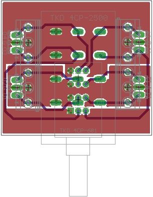 1 pointI doubt it. If you notice, the section mapping between the 601 and the 2500 is: 601 2500 2 1 3 2 1 3 4 4 The two top layer traces (section 3 on the 2500 to section 1 on the 601) could be routed on the bottom layer but they would have to go on the outside of the connectors and would be fairly long traces. The grounded pins on the pot sections for the 601 would also not correspond to a "channel". Tell me more about your desire to have the separate ground planes, and what you feel constitutes a "channel". My thoughts had been, as was done on Birgir's boards, to have the inputs on the right labeled as I1-I4 from bottom to top on the right side, and the outputs similarly on the left. I1/I2 would be a channel (+/-) and I3-I4 would be the other channel. As you can see above, if using the 601 pot, section 1 of the pot would be grounded on the L channel, but carrying the R+ signal (I3).1 point


Important Information
By using this site, you agree to our Terms of Use.
Account
Navigation
Search
Configure browser push notifications
Chrome (Android)
- Tap the lock icon next to the address bar.
- Tap Permissions → Notifications.
- Adjust your preference.
Chrome (Desktop)
- Click the padlock icon in the address bar.
- Select Site settings.
- Find Notifications and adjust your preference.
Safari (iOS 16.4+)
- Ensure the site is installed via Add to Home Screen.
- Open Settings App → Notifications.
- Find your app name and adjust your preference.
Safari (macOS)
- Go to Safari → Preferences.
- Click the Websites tab.
- Select Notifications in the sidebar.
- Find this website and adjust your preference.
Edge (Android)
- Tap the lock icon next to the address bar.
- Tap Permissions.
- Find Notifications and adjust your preference.
Edge (Desktop)
- Click the padlock icon in the address bar.
- Click Permissions for this site.
- Find Notifications and adjust your preference.
Firefox (Android)
- Go to Settings → Site permissions.
- Tap Notifications.
- Find this site in the list and adjust your preference.
Firefox (Desktop)
- Open Firefox Settings.
- Search for Notifications.
- Find this site in the list and adjust your preference.