

Leaderboard


Popular Content
Showing content with the highest reputation on 07/18/21 in Posts
-
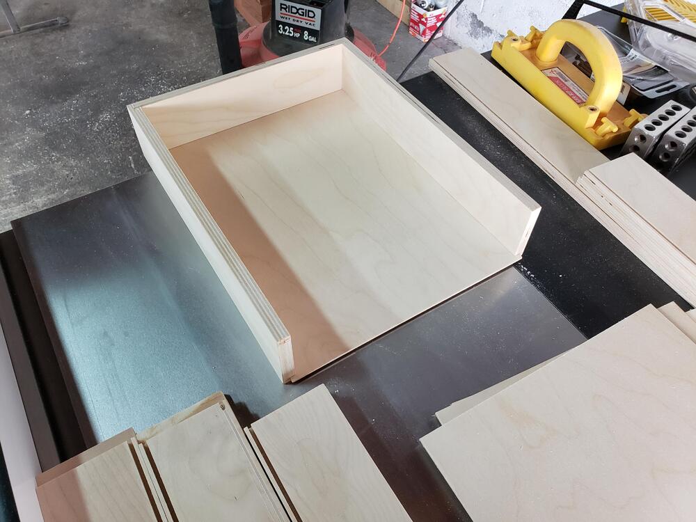
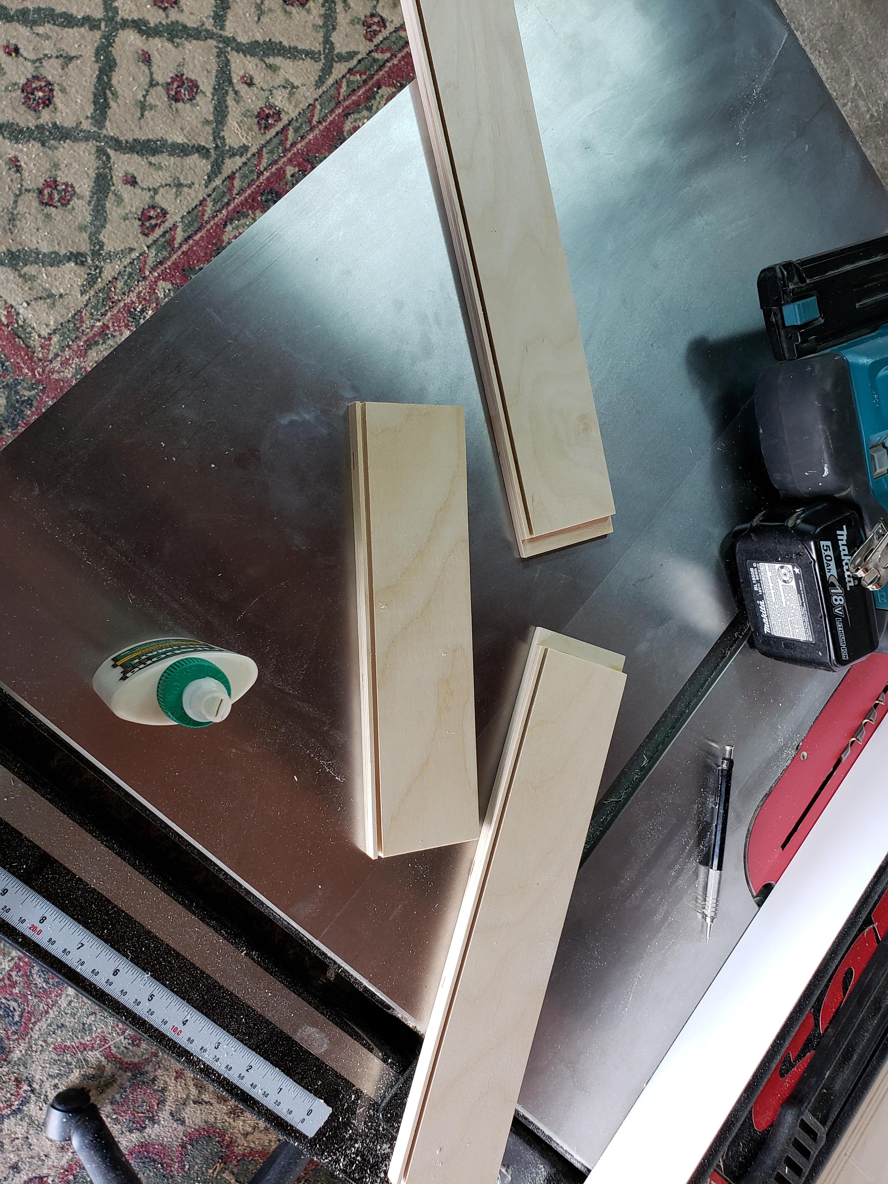
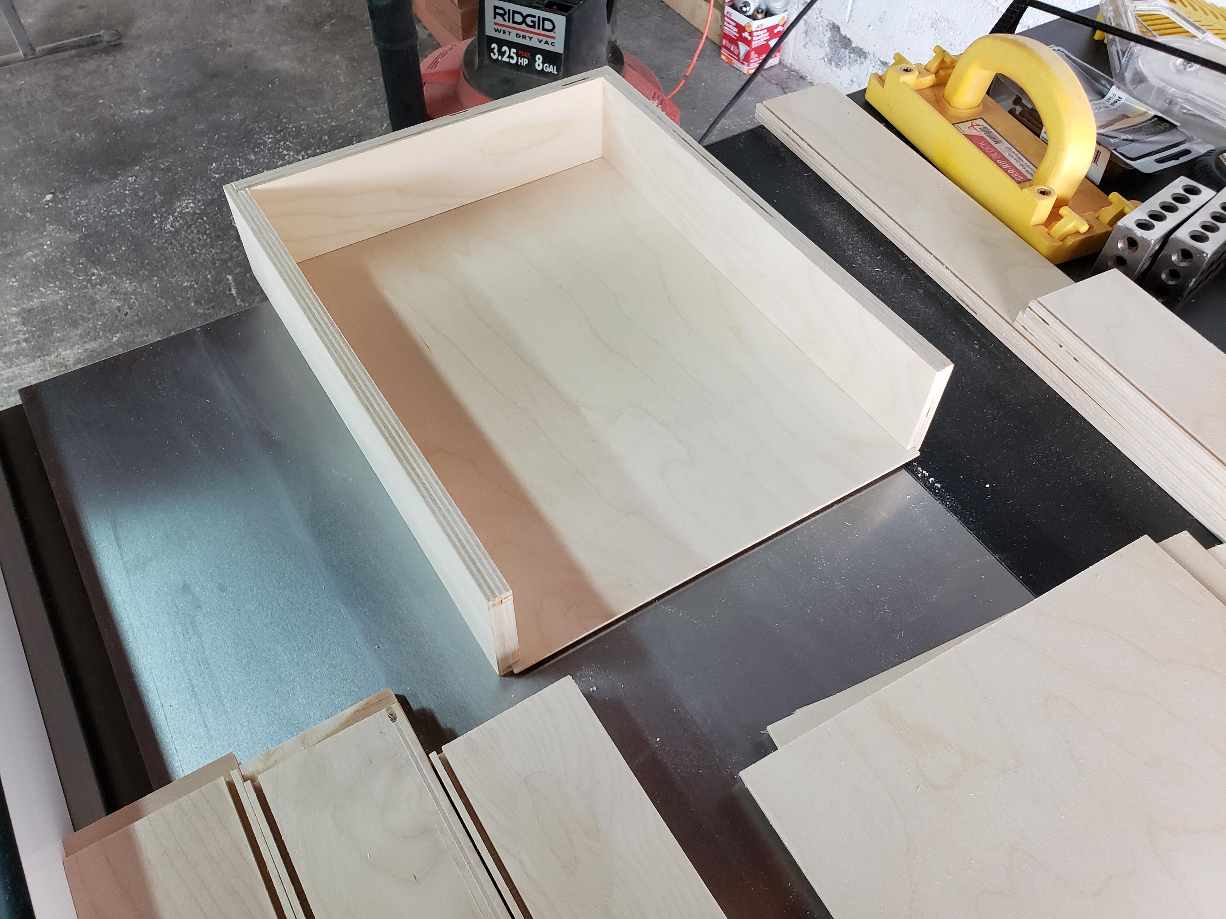
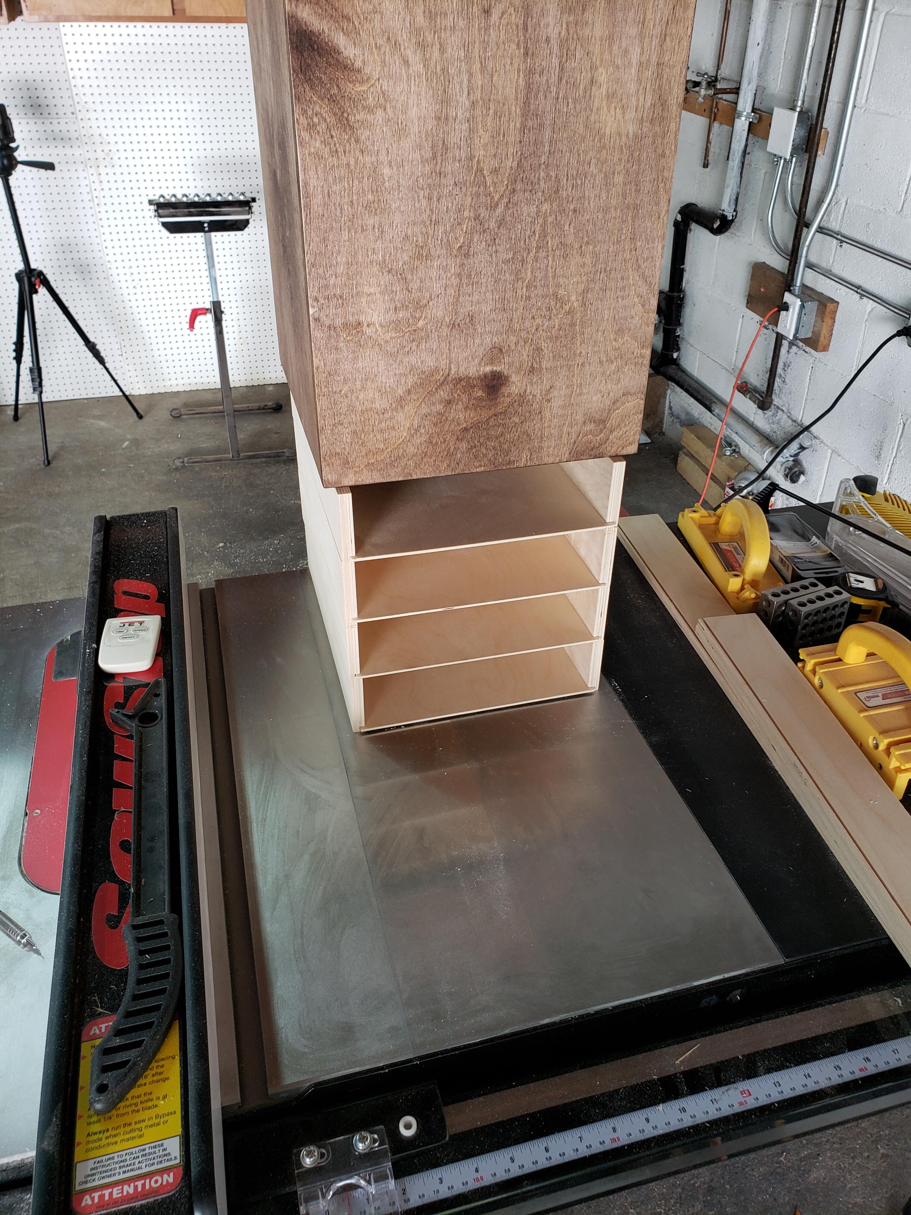
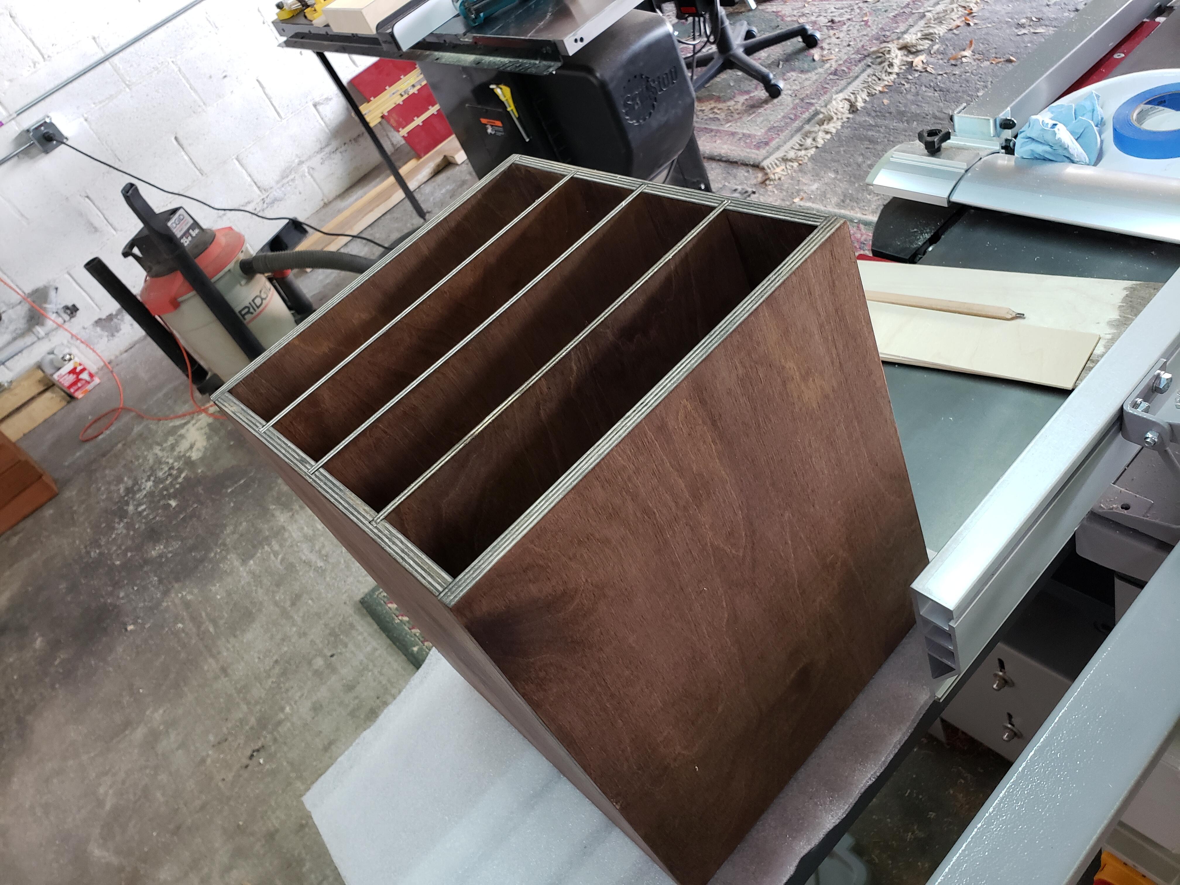
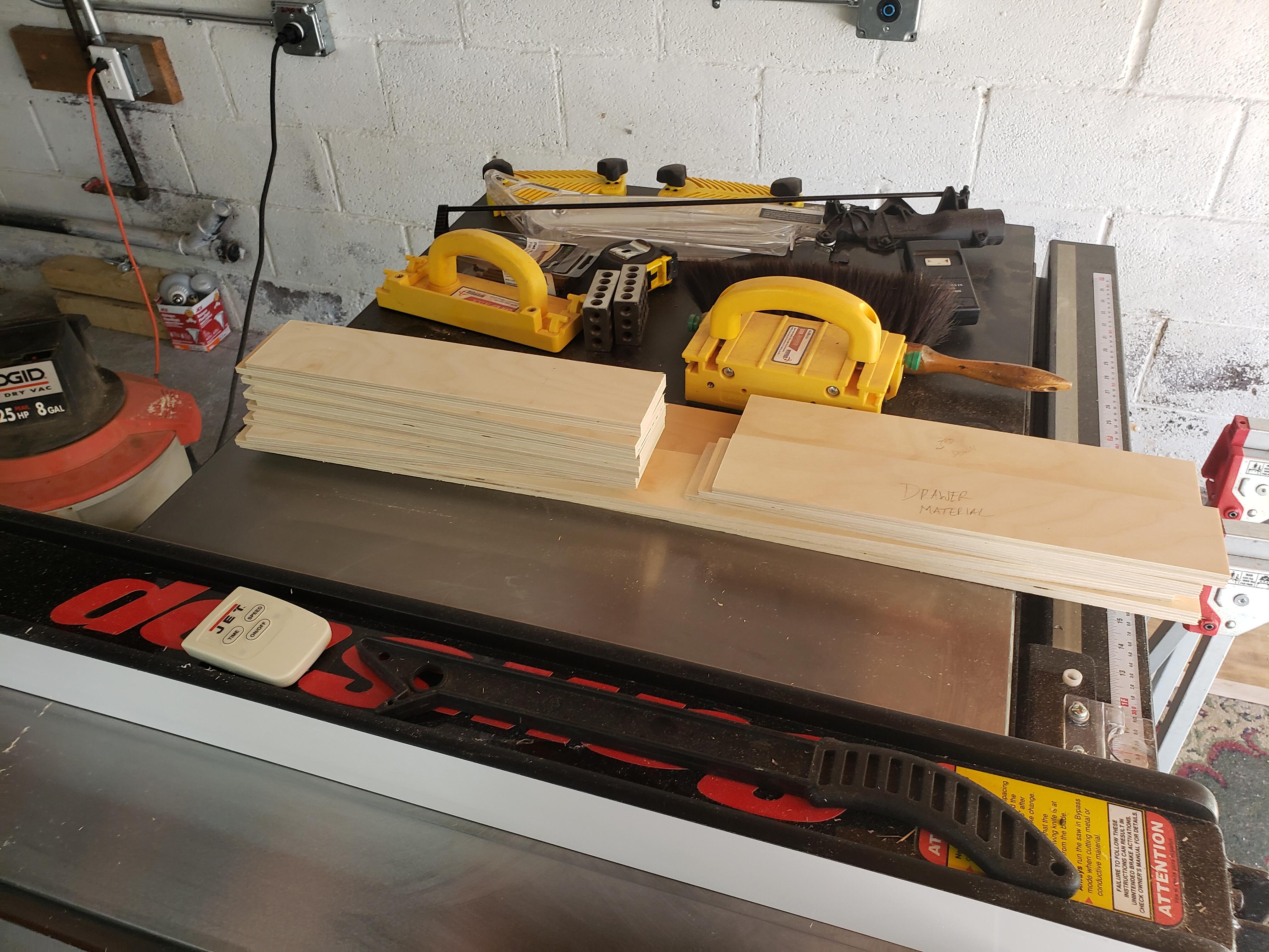
6 pointsThree sides of all four drawers are cut, assembled and bottoms slid into place. The drawers will be left natural, with a clear lacquer finish. Except the drawer fronts, which will be stained to match the box. The box sits atop the drawers for weight, to ensure that they dry flat. Tomorrow I'll cut the fronts to fit and stain them. Not sure what finish I'm going to use on the box, but I think it'll probably be boiled linseed oil, with a top coat of Tried-N-True.

 6 points
 -
4 points
-
11 Past The Hour Imelda May 2021 One of the quiet tracks - Example:3 points
-
3 points31.26 miles in 1:31:52 with 1109ft of elevation. When did you get a Class 1 Ebike?3 points
-
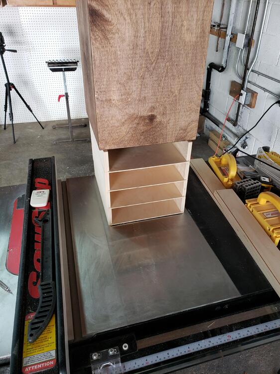
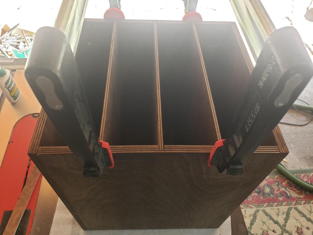
3 pointsGot the drawer dividers cut, glued and clamped up. I cut the drawer material to height, but a tad bit long and wide. I want to wait until the box cures, then I can un-clamp and measure to fit nice and snug. I have some drawer glide tape coming. This will attach to the bottom of the drawer sides and allow the drawers to slide with minimal friction. The box is too small for mechanical drawer glides.
 3 points
 -
2 points
-
Continuing the all-day DakhaBrakha love fest with Alambari
 2 points
 -
Synchronicity (Remastered 2003) The Police 1983 I feel bad for a generation that does not listen to albums - how would get to hear this masterpiece?:2 points
-
1 pointThe JAN Phillips are a nice choice to get started with though I prefer the Amperex. https://www.audiotubes.com Tube depot has a matching service as well. PS. Not sure about where to buy in Austria1 point
-
1 point1 pointGood NOS (heh) 6922s are probably rare as hell anymore. When I used to have a tube preamp (Counterpoint SA5.1) 10 years ago, I had a pair of Amperex PQ white label 6922s in it, which I really liked. The EH 6922 gold pins are quite good. If you can manage to find some vintage, you will pay out the nose for them, and possibly get ripped off. Some seemingly decent recommendations for dealers here: https://www.thegearpage.net/board/index.php?threads/online-tube-dealer-sticky.1197164/1 point1 point1 pointDecided to put in some speed work this morning since I was up at the crack of dawn seeing half the house off for a weekend (or more) of baseball in CT. Weather was pretty much perfect, warmish , no sun, virtually no wind.
 1 point1 point1 point1 point1 point1 point1 pointI've redesigned my own boards and using the RK50 typically. I'm currently using C3675 (4x for the active batteries), KSA1156, C4685A (output CCS), FJPF2145, STN9360, J79, K216.
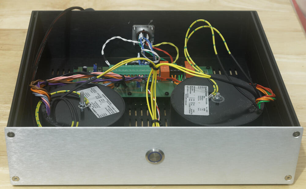
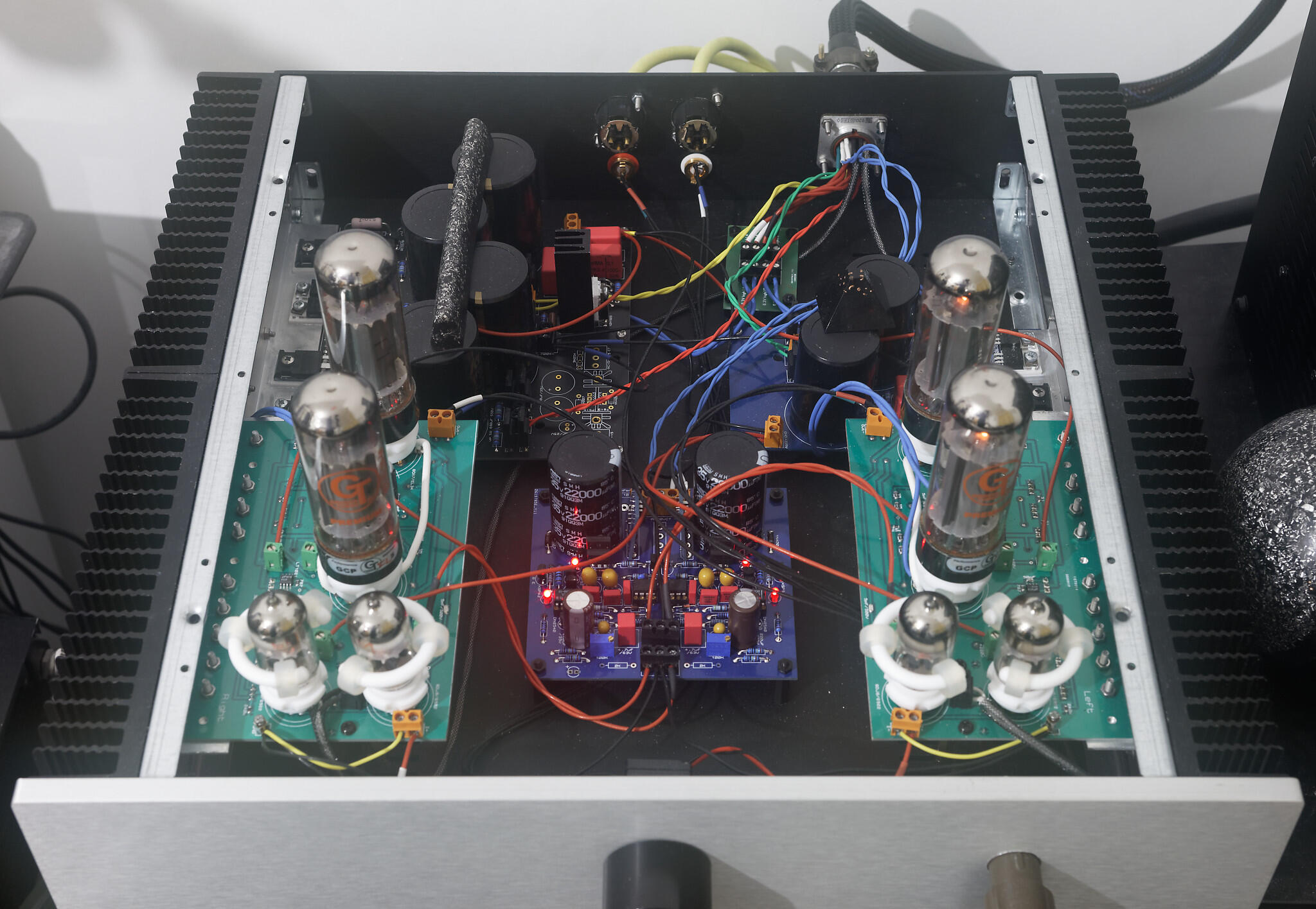
.thumb.jpg.35ea14ff655786279072f4969f8a0945.jpg) 1 point1 point1 pointFinally, my mini T2 is completed. Just want to share my build experience and listening impression for those who are about to build one. Also, a huge shout-out for JoaMat, who conceptualised and designed the amp, provided me with invaluable tips when I was debugging my mini T2 and encouraged me to share my experiences here. -------------------------------- Pics or it didn't happen: -------------------------------- Build experience: Before this amp, I have built the Carbon and Grounded Grid, as well as quite a few dynamic amps including the SMD Dynalo. Overall, I am comfortable dealing with electrostatic amp voltages, but I have limited experiences working on dense and tiny SMD boards. I built the SMD Dynalo with a soldering iron, but this method was unsuitable for the Mini T2 due to the density of the components and the fact that I tend to use copious amounts of flux grease when I solder by hand - it would be too tough to clean the flux stuck underneath the tiny components. Therefore, I decided to solder the SMD parts by the solder paste and hot-air gun method. I used 1 set of mini T2 board, 3 through-hole GRHV boards and 1 delay board (warmup.zip). This amp is fast to build so long as you have a decent hot air gun (I got mine from Taobao for around 25 USD), a pair of fine tip tweezers and some patience. I used a stencil to apply solder paste on one side of the mini T2 board first, then populated all SMD components and used the hot air gun to melt the solder paste. It was quite satisfying to see the tiny parts drawn into their rightful place by the magic of surface tension. It took me about 1 hour to complete the SMD soldering for 1 side, so I'd say that this method is really efficient for the number of parts to be populated. The through-hole components and the tube sockets were populated next, and I used some terminal blocks for the power rail inputs. Just be sure to apply jumper wire for the -15V near the servo opamp. Otherwise, you risk seeing 400V at voltage offset, and frying some input tubes. The transformers I used were 130W and 87W for the HV and LV respectively. There is also a dedicated floating 12V winding for the delay board, and separate filament supply windings are used for the power tubes and input tubes for each channel. Voltage rails were pretty standard - +-15V, +220V, +400V and -460V. The warm-up time was set to 25 sec. There is no need to adjust for output current bias as in the Carbon or GG. The balance servo is activated by default, and all there is to adjust is the output voltage offset with respect to ground, and it can be easily adjusted so long as the potentiometers are soldered to the same side as the tube sockets. The amp runs cool. I used heatsinks that measure 7cm tall, 30cm deep, 5cm wide for each side of the chassis. At steady state, the amp module runs at 39 deg C, PSU runs at 35 deg C. In comparison, my 450V 20mA biased Carbon runs at 48 deg C with 15cm-tall heatsinks. Here are some errors I encountered here and the directions I took to debug. They are based on spice simulation by JoaMat. Hopefully, my tips can help builders who encounter similar issues as I did. 1. On power-up, offset voltage rises to 400V immediately after the HV kicked in. Check the jumper connection for the opamp -15v power supply. They are very short and can be easily missed. 2. 50K resistor explodes (either R11 or R12). It is likely due to an unconnected input tube or dead tube. Check input tubes and Q1A/B, Q4/5, Q11/12, Q3A/B of the same side. Also check tube sockets, because even the expensive ones can have loose connection on NOS tubes. 3. Q1A/B burns. This might not be easy to spot. The sign can be as subtle as a discoloration/fading of the silkscreen on the component surface, or a subtle exudation of flux around the collector pin of the component. This is likely due to a shorted input tube. ------------------------------ Sound impressions Take this section with a pinch of salt, for every DIY build is one-of-a-kind, and mine is no exception. For my mini T2, I used Duelund tinned copper wire as input cable, EIZZ stepped attenuator, STAX SPC earspeaker wires as output wires and a 5-pin socket ripped from a STAX extension cable. The headphone I used was the ES1a by ES Labs. I wish I had the Stax flagships to do this impression and comparison. The amp is fed by a AK4497 DAC, straight out of DAC and a coupling capacitor, bypassing any low-pass filters. For the following impression, I used decent tubes - Mullard xf2 EL34 as output, Brimar ECC88 as V1 and Sovtek 6922 as V2. Tubes do affect the sound significantly, and I will talk about that later in the discussion. My 450V 20mA bias Carbon with GRHV&LV will be a point of reference, as I am sure that this is a sound that many here are familiar with. It has the same volume pot as the mini T2 but SPC input wires and copper output wires. The mini T2 is full sounding with a natural tone. It has got a certain “WOW” factor that makes my carbon sound unimaginative in comparison. First off, the tonality of the mini T2 is warm and mildly bright such that the sound is airy but non-fatiguing, no matter how loud I cranked the volume up. The bass extends deep with a sufficient rumble where the track calls for it. The airy top end gives the amp a wide soundstage, that is paired with sufficient depth. Instrument and vocal placement are accurate and appropriate, without excessive forwardness or recess. Despite the soundstage being big, it does not sound hollow, because the music is full of details and creates a sense of well-layered space that is almost holographic. I have tested the amp briefly with other tubes and found that input and output tubes affect the sound most significantly. If input tubes have slightly mismatched sections, the balance would be too great to be zero-ed with potentiometer and balance servo. The small tubes I used are unassuming. Had I upgraded to better tubes, I guess the amp would sound better. Compared to the Carbon, the mini T2 sounds more organic, more layered and the mids are considerably warmer. It is also way more forgiving on bad recordings. The timbre sounds truer to life, soundstage is slightly larger, and feels like the music has more room to breathe. However, bass extension is not as deep as on the Carbon, and Carbon generally feels more analytical and snappier. To conclude, if there’s one word to describe this amp, it would be “fun”. It’s fun to build and definitely fun to listen to and roll tubes. I consider it as a step up from the Carbon when I use some decent tubes. Otherwise, this amp with standard new-production tubes would be at least on par as the Carbon.1 point1 pointLately the left channel humming has increased to become even more bloody annoying. But… today I cured it (pure luck - trial and error approach). I have two umbilicals between psu and amplifier. Both carrying 580V bias and then joining at the stax connector. So, I removed left 580V bias wire in amplifier and the hum disappeared. To my ears the amplifier is now dead silent.1 pointhttps://www.shun-teh.com.tw/en/category/Aluminum-Extrusion-Heat-Sink-Above-width-200mm/A03.html This company can cut heat sink size and drill screw thread holes according your drawing, even if you only need two piece. It is good choice if you want to design your own case.1 point1 pointI used two transformers. both with electromagnetic shields, static shields and potted from http://www.mueller-rondo.com/kontakt.htm . (The low voltage transformer can be used for the blue hawaii - the 6922 windings are just not used the other voltages and currents are fine.) low voltage: transformer two windings 6.3V 4.5A for EL34 heaters one winding for each channel NOTE these windings are -400VDC to ground two windings 6.3V 1.5A for 6992 heaters one for each channel and my HT delay board two windings 15.5V 0.4A for golden reference LV board + and - 15VDC high voltage transformer one winding 365V 0.2A for dual golden reference HV board -460VDC. NOTE 365VAC gives 516VDC which gives less than 10% margin before reaching the 550V limit of most high voltage 550V 470uF input caps on the golden reference HV... so be careful if your household mains voltages are usually higher than spec. one winding 322V 0.2A for dual golden reference HV board +400VDC and +580V stax bias one winding 192V 0.18A for golden reference HV board +220VDC The blue hawaii just fits in a single 2u case 400mm deep, using 1 transformer with less windings - one less high voltage and two less 6.3V, golden reference LV board and golden reference HV board. The mini T2 has two transformers AND an extra HV board so the issue is not height but depth, to give you a size idea the transformers are Low voltage diameter 105mm height 55mm High voltage diameter 115mm height 65mm not having shields in the transformers will result in some hum and electrical interference if you turn the volume all the way up if you go single case. Not potting the transformers might make them a little smaller. putting the transformers into a separate case makes both the blue hawaii and mini t2 absolutely silent. you cant easily use the space bellow the mini t2 amp boards because they have 4 pillars which screw into the bottom of the case so you don't bend the amp boards when inserting or removing the valves. Neither the golden reference LV or HV boards will fit bellow the am boards because of this. for both my blue hawaii and mini t2 builds I went with the following case https://modushop.biz/site/index.php?route=product/product&path=102&product_id=195 its 2u, 400mm deep and has large heat sinking and is fully aluminium so fairly easy to drill. The heat sinking is overkill for the mini t2 - which runs quite cool, but the blue hawaii needs those large heat sinks, For the umbilical chord I used 1KV silicon rubber multi-strand copper hookup wires (https://www.mouser.co.uk/Search/Refine?Keyword=CT2956) for good flexibility and Russian 19 pin military connectors (https://www.ebay.co.uk/itm/19-pin-Soviet-Military-connector-Female-Male-Set-Oty-1/254196620095?ssPageName=STRK%3AMEBIDX%3AIT&_trksid=p2057872.m2749.l2649). I then covered the bundle with expandable nylon braid and tested the leads with an insulation tester and they passed 5 minutes at 2500V with 20+Gohm resistance. They failed insulation at 5KV. P.S. if you build golden reference HV boards kemet do 550V 470uF caps which are 65mm high and will fit in a 2u case https://www.mouser.co.uk/Passive-Components/_/N-5g73Z1yzvvqx?Keyword=kemet+550V+470uF&FS=True. Be careful Kemet also sell 680uF 550V caps that are 80mm high and will need a 3u case to fit . (https://www.mouser.co.uk/ProductDetail/KEMET/ALC10A681EL550?qs=%2Fha2pyFadug678O2NPlQ%2F8WMW0dBZWV2y30oREQu6XgezeenvV90cA%3D%3D). for the +220VDC golden ref board you can save some money and go kemet 470uf 450V or even 400V. I didnt simply because I might re-purpose the 220V board to a higher voltage sometime.But the 550v 470uF kemet caps are not cheap. P.S. the golden reference LV board is not necessary, only the servos are run from the + and - 15V lines so you could just populate the low voltage section of the GRHV board. However, if you don't want thumps on switch-off the + and -12V lines require large capacitors so the servos stay powered while the HV lines fade. I found ~15000uF to 22000uF is required but these caps are physically too large to fit in the simple LV section of the GRHV board. They fit fine in the GRLV board, but a full GRLV board is extra expense just to avoid switch off thump. I use GRLV boards in lots of projects so again they can be repurposed...
1 point1 point1 pointFinally, my mini T2 is completed. Just want to share my build experience and listening impression for those who are about to build one. Also, a huge shout-out for JoaMat, who conceptualised and designed the amp, provided me with invaluable tips when I was debugging my mini T2 and encouraged me to share my experiences here. -------------------------------- Pics or it didn't happen: -------------------------------- Build experience: Before this amp, I have built the Carbon and Grounded Grid, as well as quite a few dynamic amps including the SMD Dynalo. Overall, I am comfortable dealing with electrostatic amp voltages, but I have limited experiences working on dense and tiny SMD boards. I built the SMD Dynalo with a soldering iron, but this method was unsuitable for the Mini T2 due to the density of the components and the fact that I tend to use copious amounts of flux grease when I solder by hand - it would be too tough to clean the flux stuck underneath the tiny components. Therefore, I decided to solder the SMD parts by the solder paste and hot-air gun method. I used 1 set of mini T2 board, 3 through-hole GRHV boards and 1 delay board (warmup.zip). This amp is fast to build so long as you have a decent hot air gun (I got mine from Taobao for around 25 USD), a pair of fine tip tweezers and some patience. I used a stencil to apply solder paste on one side of the mini T2 board first, then populated all SMD components and used the hot air gun to melt the solder paste. It was quite satisfying to see the tiny parts drawn into their rightful place by the magic of surface tension. It took me about 1 hour to complete the SMD soldering for 1 side, so I'd say that this method is really efficient for the number of parts to be populated. The through-hole components and the tube sockets were populated next, and I used some terminal blocks for the power rail inputs. Just be sure to apply jumper wire for the -15V near the servo opamp. Otherwise, you risk seeing 400V at voltage offset, and frying some input tubes. The transformers I used were 130W and 87W for the HV and LV respectively. There is also a dedicated floating 12V winding for the delay board, and separate filament supply windings are used for the power tubes and input tubes for each channel. Voltage rails were pretty standard - +-15V, +220V, +400V and -460V. The warm-up time was set to 25 sec. There is no need to adjust for output current bias as in the Carbon or GG. The balance servo is activated by default, and all there is to adjust is the output voltage offset with respect to ground, and it can be easily adjusted so long as the potentiometers are soldered to the same side as the tube sockets. The amp runs cool. I used heatsinks that measure 7cm tall, 30cm deep, 5cm wide for each side of the chassis. At steady state, the amp module runs at 39 deg C, PSU runs at 35 deg C. In comparison, my 450V 20mA biased Carbon runs at 48 deg C with 15cm-tall heatsinks. Here are some errors I encountered here and the directions I took to debug. They are based on spice simulation by JoaMat. Hopefully, my tips can help builders who encounter similar issues as I did. 1. On power-up, offset voltage rises to 400V immediately after the HV kicked in. Check the jumper connection for the opamp -15v power supply. They are very short and can be easily missed. 2. 50K resistor explodes (either R11 or R12). It is likely due to an unconnected input tube or dead tube. Check input tubes and Q1A/B, Q4/5, Q11/12, Q3A/B of the same side. Also check tube sockets, because even the expensive ones can have loose connection on NOS tubes. 3. Q1A/B burns. This might not be easy to spot. The sign can be as subtle as a discoloration/fading of the silkscreen on the component surface, or a subtle exudation of flux around the collector pin of the component. This is likely due to a shorted input tube. ------------------------------ Sound impressions Take this section with a pinch of salt, for every DIY build is one-of-a-kind, and mine is no exception. For my mini T2, I used Duelund tinned copper wire as input cable, EIZZ stepped attenuator, STAX SPC earspeaker wires as output wires and a 5-pin socket ripped from a STAX extension cable. The headphone I used was the ES1a by ES Labs. I wish I had the Stax flagships to do this impression and comparison. The amp is fed by a AK4497 DAC, straight out of DAC and a coupling capacitor, bypassing any low-pass filters. For the following impression, I used decent tubes - Mullard xf2 EL34 as output, Brimar ECC88 as V1 and Sovtek 6922 as V2. Tubes do affect the sound significantly, and I will talk about that later in the discussion. My 450V 20mA bias Carbon with GRHV&LV will be a point of reference, as I am sure that this is a sound that many here are familiar with. It has the same volume pot as the mini T2 but SPC input wires and copper output wires. The mini T2 is full sounding with a natural tone. It has got a certain “WOW” factor that makes my carbon sound unimaginative in comparison. First off, the tonality of the mini T2 is warm and mildly bright such that the sound is airy but non-fatiguing, no matter how loud I cranked the volume up. The bass extends deep with a sufficient rumble where the track calls for it. The airy top end gives the amp a wide soundstage, that is paired with sufficient depth. Instrument and vocal placement are accurate and appropriate, without excessive forwardness or recess. Despite the soundstage being big, it does not sound hollow, because the music is full of details and creates a sense of well-layered space that is almost holographic. I have tested the amp briefly with other tubes and found that input and output tubes affect the sound most significantly. If input tubes have slightly mismatched sections, the balance would be too great to be zero-ed with potentiometer and balance servo. The small tubes I used are unassuming. Had I upgraded to better tubes, I guess the amp would sound better. Compared to the Carbon, the mini T2 sounds more organic, more layered and the mids are considerably warmer. It is also way more forgiving on bad recordings. The timbre sounds truer to life, soundstage is slightly larger, and feels like the music has more room to breathe. However, bass extension is not as deep as on the Carbon, and Carbon generally feels more analytical and snappier. To conclude, if there’s one word to describe this amp, it would be “fun”. It’s fun to build and definitely fun to listen to and roll tubes. I consider it as a step up from the Carbon when I use some decent tubes. Otherwise, this amp with standard new-production tubes would be at least on par as the Carbon.1 point1 pointLately the left channel humming has increased to become even more bloody annoying. But… today I cured it (pure luck - trial and error approach). I have two umbilicals between psu and amplifier. Both carrying 580V bias and then joining at the stax connector. So, I removed left 580V bias wire in amplifier and the hum disappeared. To my ears the amplifier is now dead silent.1 pointhttps://www.shun-teh.com.tw/en/category/Aluminum-Extrusion-Heat-Sink-Above-width-200mm/A03.html This company can cut heat sink size and drill screw thread holes according your drawing, even if you only need two piece. It is good choice if you want to design your own case.1 point1 pointI used two transformers. both with electromagnetic shields, static shields and potted from http://www.mueller-rondo.com/kontakt.htm . (The low voltage transformer can be used for the blue hawaii - the 6922 windings are just not used the other voltages and currents are fine.) low voltage: transformer two windings 6.3V 4.5A for EL34 heaters one winding for each channel NOTE these windings are -400VDC to ground two windings 6.3V 1.5A for 6992 heaters one for each channel and my HT delay board two windings 15.5V 0.4A for golden reference LV board + and - 15VDC high voltage transformer one winding 365V 0.2A for dual golden reference HV board -460VDC. NOTE 365VAC gives 516VDC which gives less than 10% margin before reaching the 550V limit of most high voltage 550V 470uF input caps on the golden reference HV... so be careful if your household mains voltages are usually higher than spec. one winding 322V 0.2A for dual golden reference HV board +400VDC and +580V stax bias one winding 192V 0.18A for golden reference HV board +220VDC The blue hawaii just fits in a single 2u case 400mm deep, using 1 transformer with less windings - one less high voltage and two less 6.3V, golden reference LV board and golden reference HV board. The mini T2 has two transformers AND an extra HV board so the issue is not height but depth, to give you a size idea the transformers are Low voltage diameter 105mm height 55mm High voltage diameter 115mm height 65mm not having shields in the transformers will result in some hum and electrical interference if you turn the volume all the way up if you go single case. Not potting the transformers might make them a little smaller. putting the transformers into a separate case makes both the blue hawaii and mini t2 absolutely silent. you cant easily use the space bellow the mini t2 amp boards because they have 4 pillars which screw into the bottom of the case so you don't bend the amp boards when inserting or removing the valves. Neither the golden reference LV or HV boards will fit bellow the am boards because of this. for both my blue hawaii and mini t2 builds I went with the following case https://modushop.biz/site/index.php?route=product/product&path=102&product_id=195 its 2u, 400mm deep and has large heat sinking and is fully aluminium so fairly easy to drill. The heat sinking is overkill for the mini t2 - which runs quite cool, but the blue hawaii needs those large heat sinks, For the umbilical chord I used 1KV silicon rubber multi-strand copper hookup wires (https://www.mouser.co.uk/Search/Refine?Keyword=CT2956) for good flexibility and Russian 19 pin military connectors (https://www.ebay.co.uk/itm/19-pin-Soviet-Military-connector-Female-Male-Set-Oty-1/254196620095?ssPageName=STRK%3AMEBIDX%3AIT&_trksid=p2057872.m2749.l2649). I then covered the bundle with expandable nylon braid and tested the leads with an insulation tester and they passed 5 minutes at 2500V with 20+Gohm resistance. They failed insulation at 5KV. P.S. if you build golden reference HV boards kemet do 550V 470uF caps which are 65mm high and will fit in a 2u case https://www.mouser.co.uk/Passive-Components/_/N-5g73Z1yzvvqx?Keyword=kemet+550V+470uF&FS=True. Be careful Kemet also sell 680uF 550V caps that are 80mm high and will need a 3u case to fit . (https://www.mouser.co.uk/ProductDetail/KEMET/ALC10A681EL550?qs=%2Fha2pyFadug678O2NPlQ%2F8WMW0dBZWV2y30oREQu6XgezeenvV90cA%3D%3D). for the +220VDC golden ref board you can save some money and go kemet 470uf 450V or even 400V. I didnt simply because I might re-purpose the 220V board to a higher voltage sometime.But the 550v 470uF kemet caps are not cheap. P.S. the golden reference LV board is not necessary, only the servos are run from the + and - 15V lines so you could just populate the low voltage section of the GRHV board. However, if you don't want thumps on switch-off the + and -12V lines require large capacitors so the servos stay powered while the HV lines fade. I found ~15000uF to 22000uF is required but these caps are physically too large to fit in the simple LV section of the GRHV board. They fit fine in the GRLV board, but a full GRLV board is extra expense just to avoid switch off thump. I use GRLV boards in lots of projects so again they can be repurposed...
 1 point


.jpg.1a65716e83cacbc65794651e1441c5b7.jpg)


Important Information
By using this site, you agree to our Terms of Use.