Leaderboard


Popular Content
Showing content with the highest reputation on 08/20/23 in all areas
-
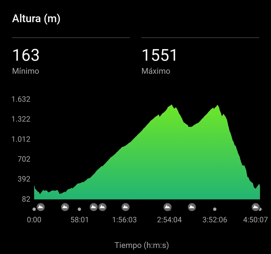
Crossed the 1/3 mark yesterday, thanks folks. Logged some solid training miles this morning before the rest of the family was awake.
(2).thumb.jpg.738e5dcbcafa674b1df776aea87b850c.jpg) 4 points
4 points -
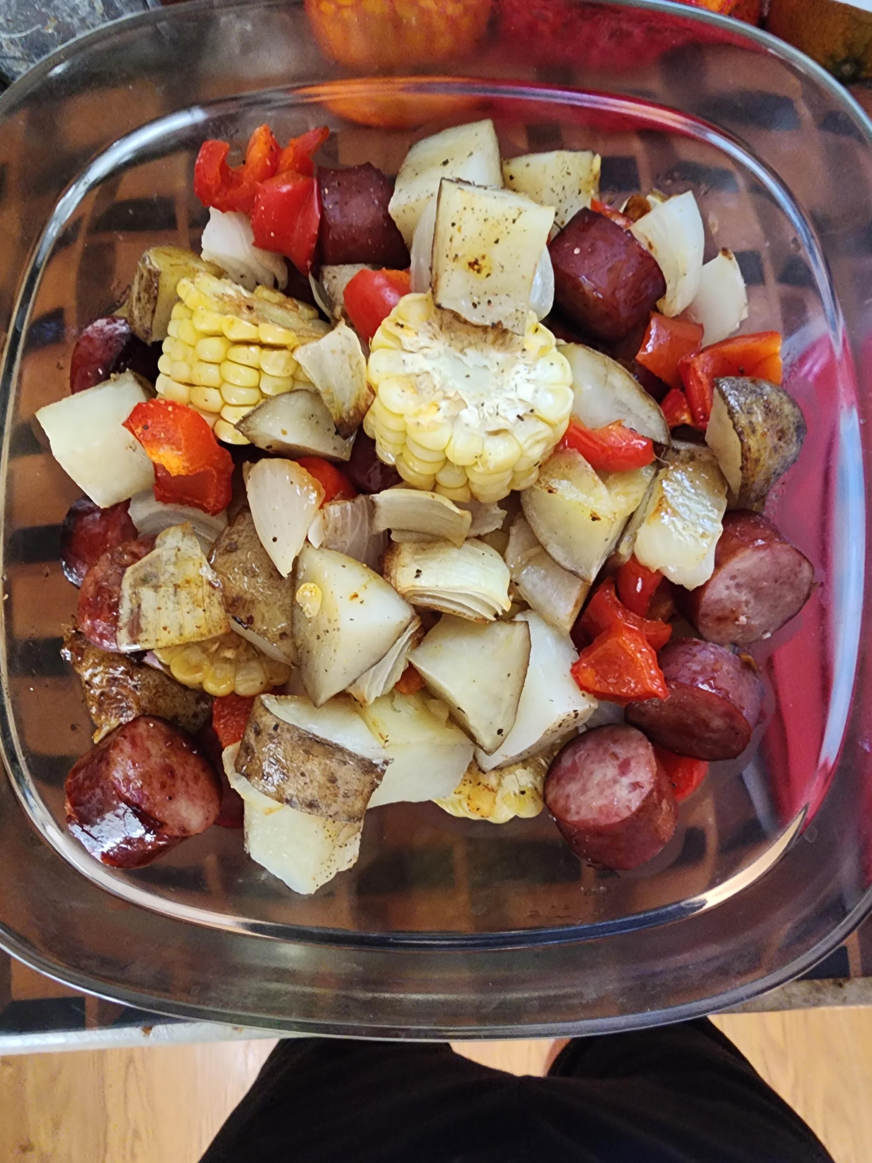
3 pointsPrepped and started cooking one of my favorite sheet pan meals for dinner tonight, and to munch on for the next several days. About 15 minutes in the oven, Al's Sister Rinni and Neice Dorothy called and wanted to meet out for dinner. Never turning down a fun time with this Mother/Daughter duo, the meal will go into the fridge for a meal tomorrow. I'll pick up a loaf of Good Earth's baguette while I'm out, and that'll make it even better. Italian tonight. Maybe a good salad too.
 3 points
 -
Noice! The analog espresso is the best out of the three I tried (analog, organic, and I forget the third one). It's my favourite store-buyable coffee by far, and not just because it says "black cat" on it. 😺2 points
-
My Blackcat analog showed up...yay. I ran out of espresso and have been using Inteligentsia Summer Solstice Blend from my last order and it's made supper espresso drinks albeit a bit of work to dial in. HS
 2 points
 -
Jon Batiste - World Music Radio I'm amazed that these guys at Odesli keep adding streaming services but they won't include Qobuz1 point
-
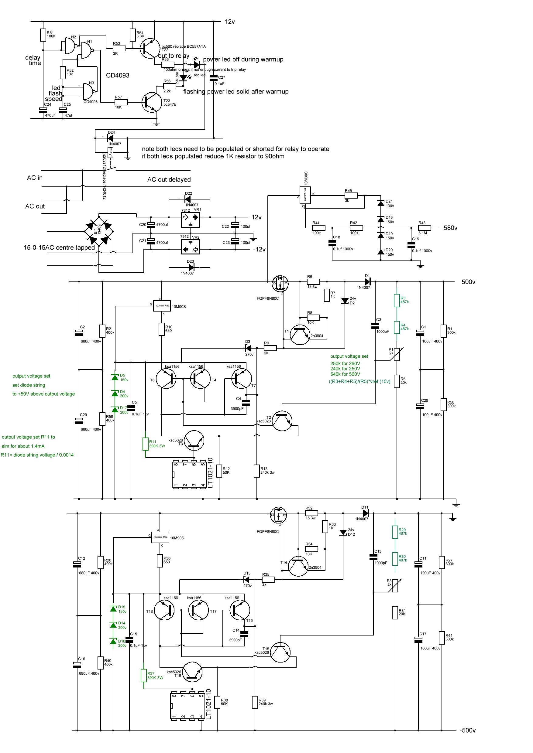
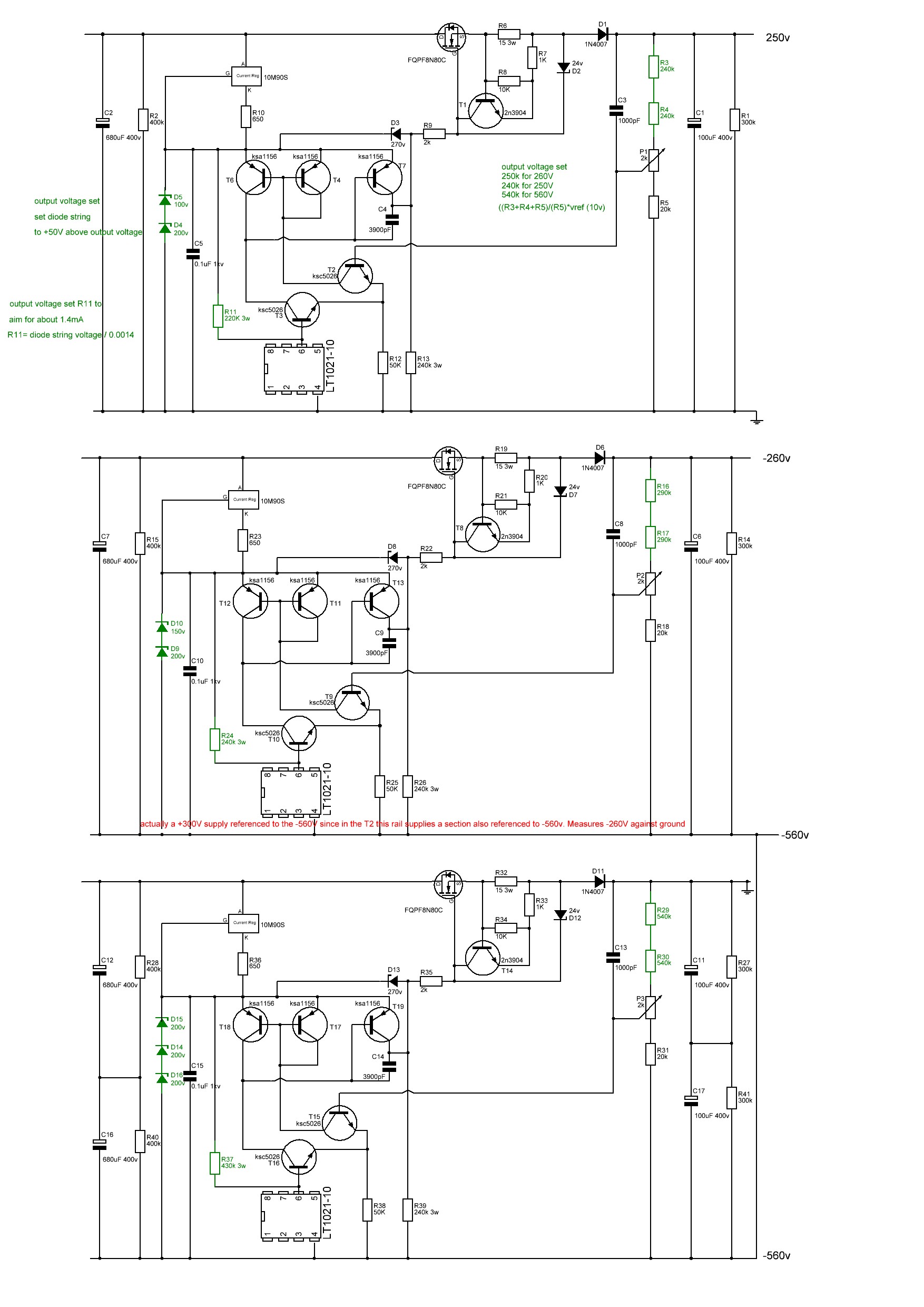
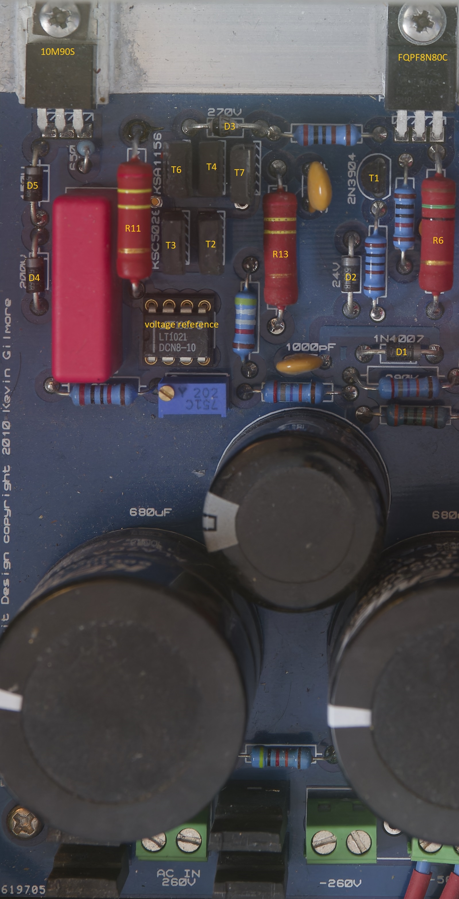
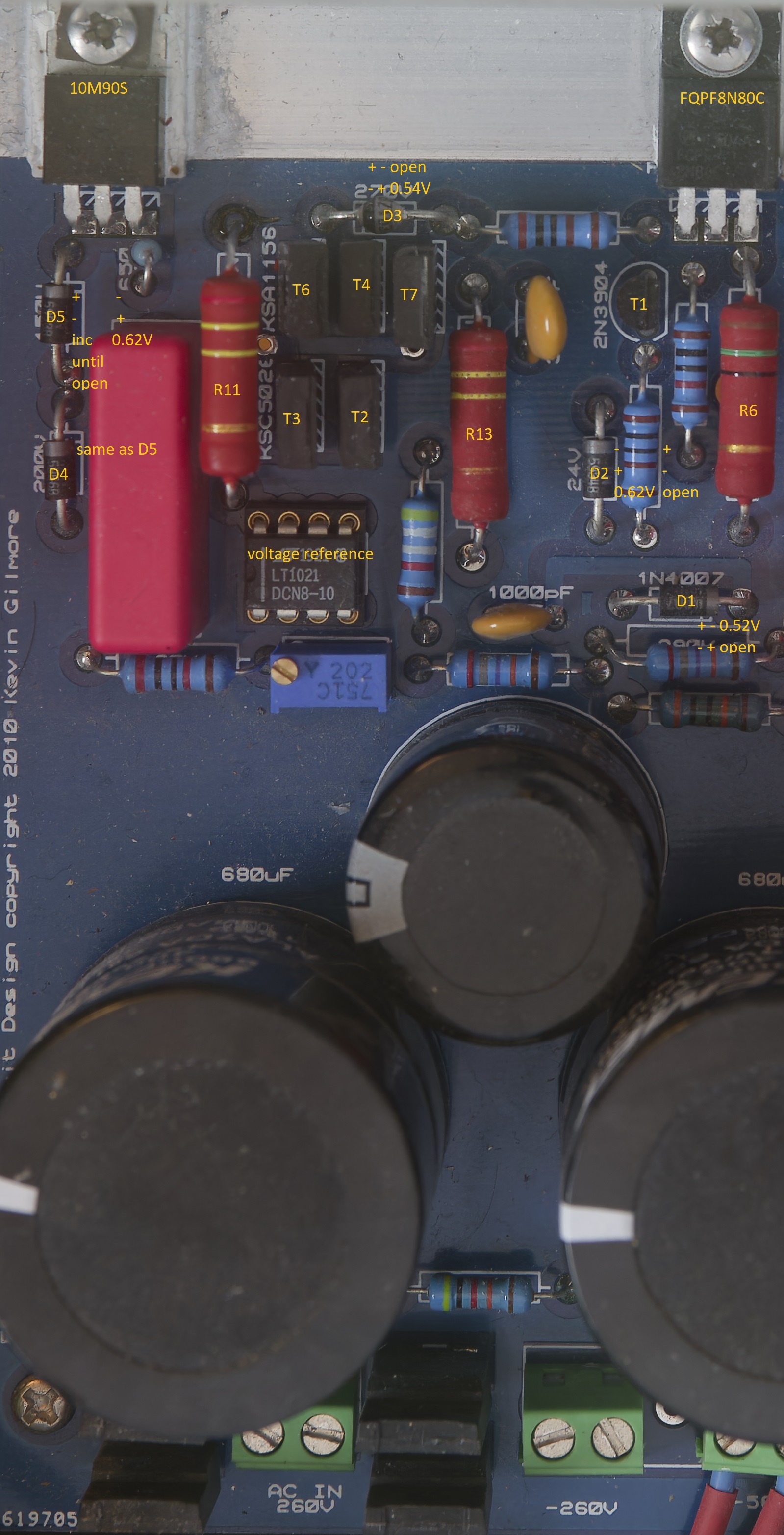
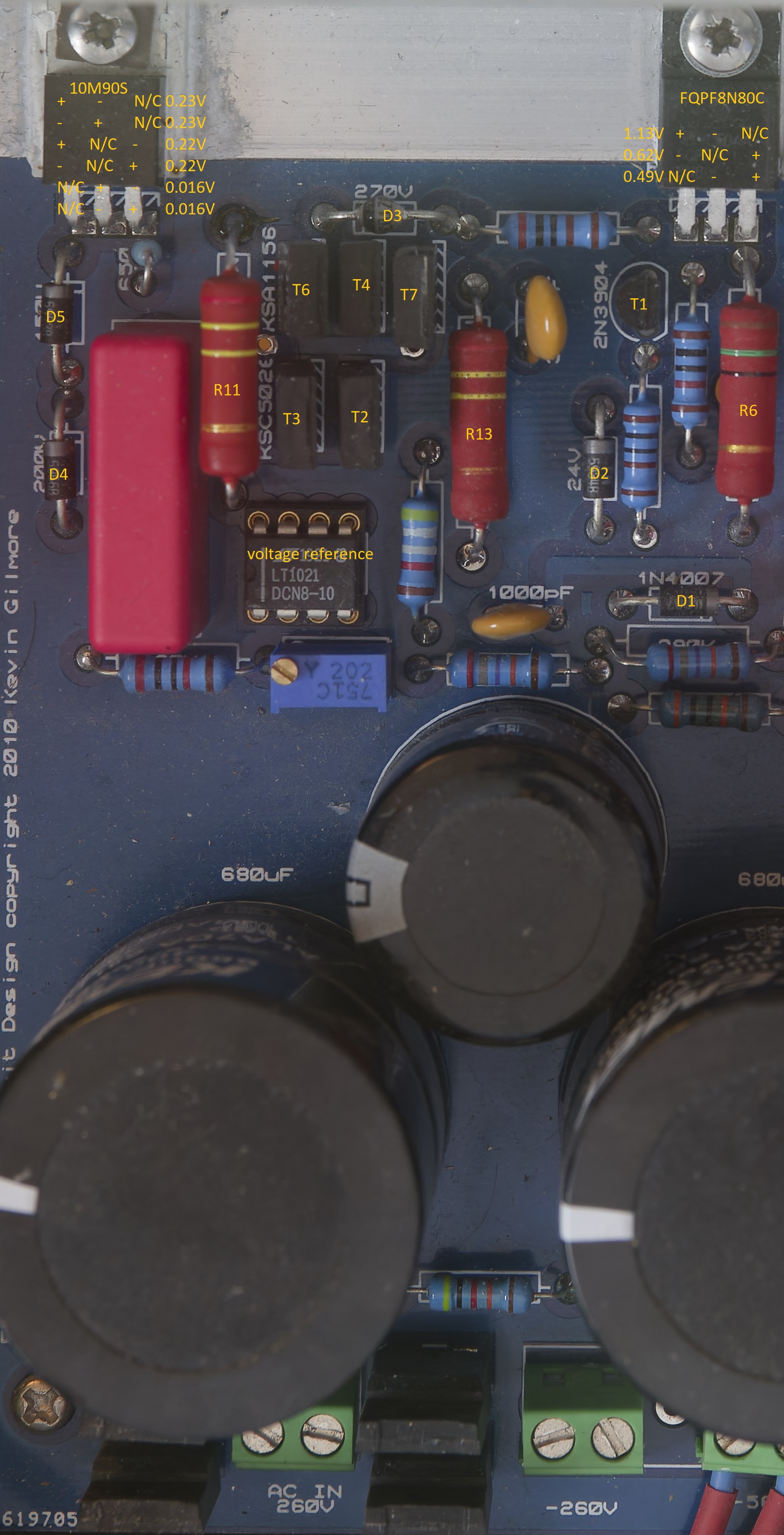
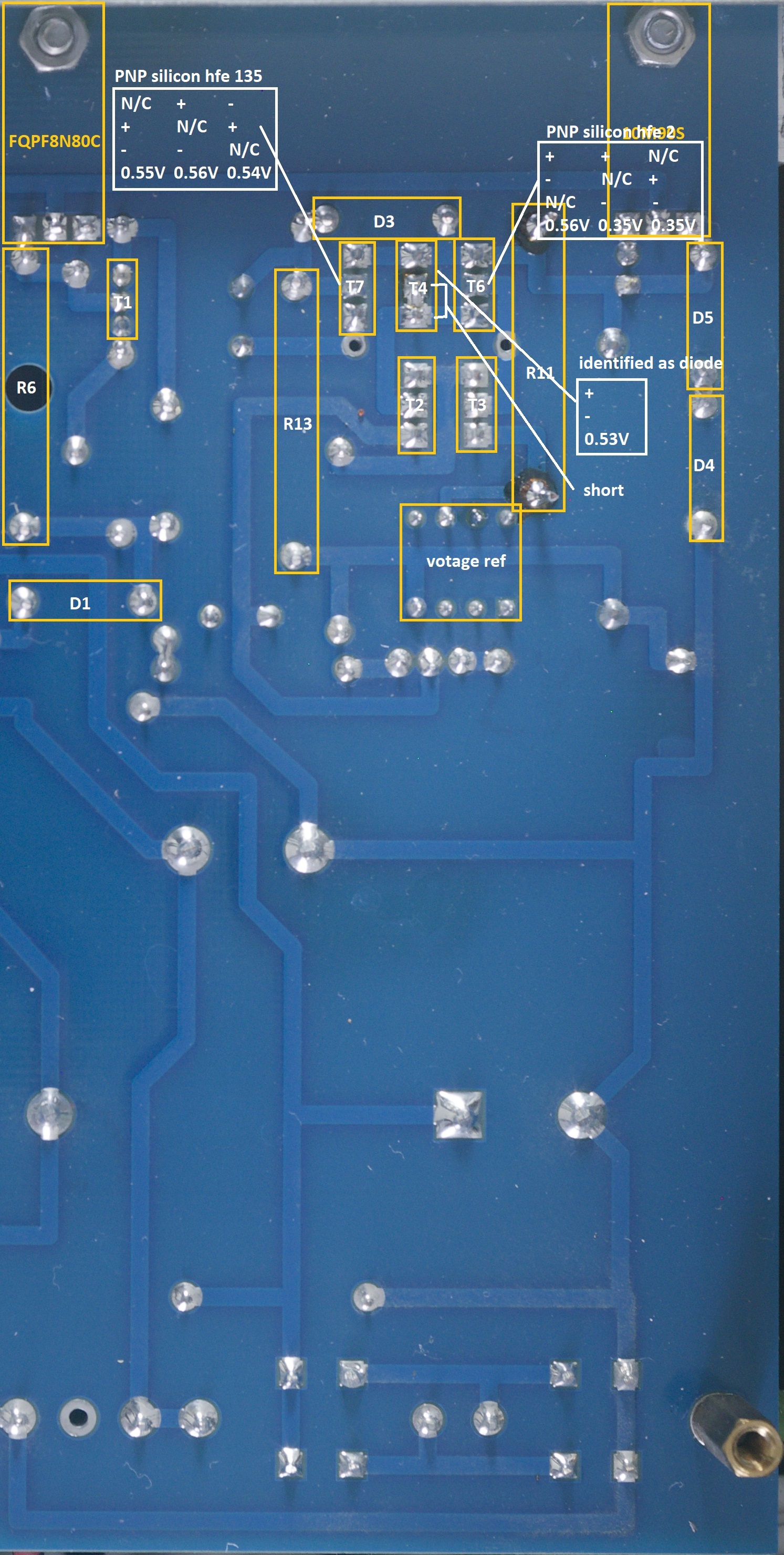
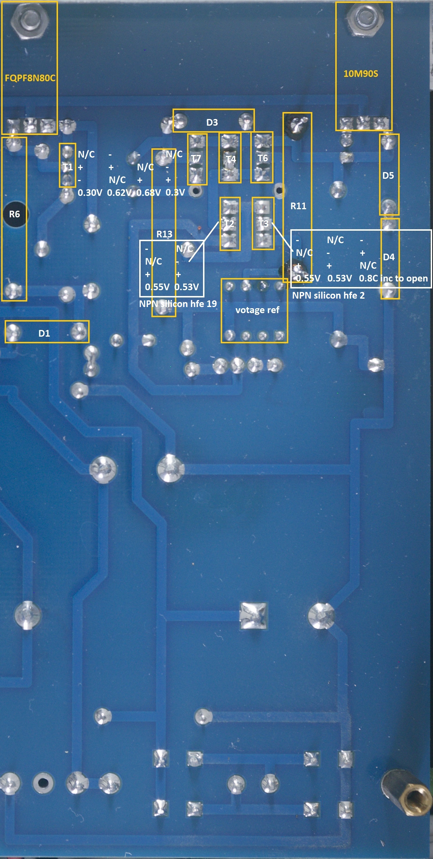
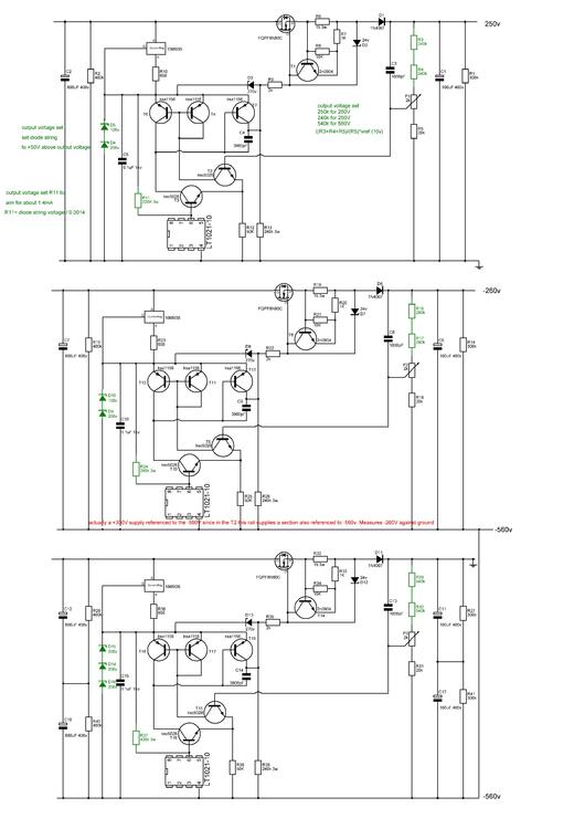
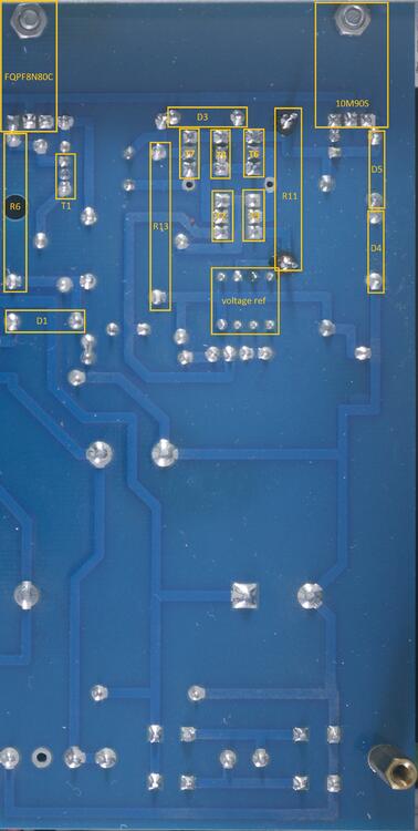
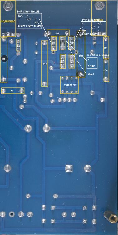
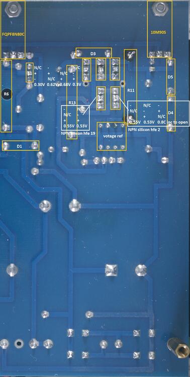
1 pointSince the T2 needs a complex power supply I am also including a T2 power supply testing guide. There are multiple options for the T2 power supply but the one I built is: The gerbers can be found here: <insert link> The guide is intended for both pre-power on verification of an amp build, verification of voltages on power on and general troubleshooting. All tests are performed using a Brymen BM869s and peak DCA75. Using a different multimeter may effect the results slightly but you should still get similar behaviours and ball-park figures. All tests are performed with the psu not connected to an amp and no mains transformer connected. unfortunately many of the transistors are packed tightly together so it is not easy or really possible to get test probes onto all the legs of all the transistors from the top and so the verification guide will be separated into two halves: testing from the top and testing from the bottom. Since all the high voltage power supplies are basically identical except for differing values for some resistors ad the pre regulator zeners I will cover one psu rai and the diode tests and dca75 tests should be the same for the other high voltage rails. (The 500V and above rails also have two caps in series with bleed resistors in parallel for the input smoothing and output smoothing to reduce the financial cost of the caps and increase the cap options) The low voltage rails are trivial - diode bridge, bulk cap, monolithic off the shelf regulator and smoothing cap and so will not be covered. NOTE the 3w resistor which direct connects to the 10 volt reference will get hot (depending upon the supply rail) it can reach 80C+, If you look at my schematics above I suggest increasing the value of the resistor to reduce the current and decrease the temperature. Also raise it from the pcb as much as possible to keep it away from the nearby 0.1uF capacitor. NOTE if you use 0.1% precision resistors for the output voltage set resistors then they must be rated at above 250V for the 560V rail or (in my experience if you use 250V rated working voltage resistors their resistance will drift higher and higher with time and the 560V rail will eventually hit the zener string voltage of 600V and this will cause an uncorrectable dc offset in your T2 amp). Transistor and diode location Top The two ksc5026 (T3 and T2) form a long tail pair with T3 input being the 10V reference and T2 input being the the voltage across R5 (and half of P1) in the voltage set string. To improve the performance of the differential amp T6 and T4 form a current mirror. R12 is the common resistor for the long tail. The output of the long tail comes from the collector of T3 and goes to T7. Probe Tests from above Diode test of the zener pre regulator D5 and D4 measuring across each separately, you will get about 0.6V drop, probes reversed the multimeter will register a steadily increasing voltage until it shows open. This is true of each zener in the string. Diode test D2 you will get about 0.6v drop in one direction and an instant open in the other Diode test D1 you will get about 0.52v drop in one direction and an instant open in the other Diode test D3 you will get about 0.54v drop in one direction and an instant open in the other Note it is possible for a transistor to fail in such a way it has very little gain but still has a diode drop and so diode checking transistors is not a foolproof measure of a transistors health. But 0V drop when not expected indicates a short etc. Diode and dca75 tests of the 10m90s NOTE the 10m90s has a live tab and absolutely must be insulated from the heatsink it is mounted to. Like the 10m90s in the t2 amp boards the 10m90s measures the same when the polarity of the probes has been reversed. Just like the T2 amp the peak dca75 can't identify this component in circuit and variously shows it as a low voltage zener ~ 1.6V or an led. Diode and dca75 tests of the fqp8n80s The peak dca75 can't identify this component in circuit and variously misidentifies it as two diodes or a diode and led. Diode checks from underside Transistor and diode location Bottom Diode test T1 2N3904 NPN transistor. forms the active part of the current limit circuit. It monitors the current through R15 and when the voltage drop across the resistor gets too high T1 starts to cut off the pass mosfet FQPF8M80C. If you get correct voltage output with no load but any load massively decreases the output down to about 75V suspect T1 has gone short circuit. Diode and DCA 75 test T2 and T3 KSC5026 NPN transistor. These form the long tail pair differential amp which compares the voltage reference against a portion of the output voltage controlled by the trimmer P1 and the series resistor ladder R3, R4 R5. There should be very close to 10V across R5 if not one possibility is R3 and R4 have too higher a resistance value, possibility from using resistors with a too low working voltage - especially in the -560V rail which puts more than 250V across each of R3 and R4 in the series ladder. NOTE T2 is connected to a both ends of a cap and so this cap will slowly charge resulting in the diode test reading showing an increasing voltage drop until the multimeter finally displays open when the cap has charged to the same voltage as the meter outputs and so no current flows at all fooling the meter into thinking there is an open circuit. This does not occur with T3 The dca75 reliably and correctly identifies T2 as a NPN silicon transistor hfe 19 and T3 as a NPN silicon transistor hfe 2. Diode and DCA75 test T4, T6 T7. Ksa156 PNP transistor. T4 and T6 form the current mirror for the long pair differential amp. NOTE T4 has base and collector shorted together and so measures similarly to a single diode. The DCA correctly and reliably identifies T7 as a PNP transistor hfe 135 The DCA obviously identifies T4 as a diode junction if you don't connect the 3rd lead, otherwise it just reports a short between two of the leads - which is correct. The DCA correctly and reliably identifies T6 as a PNP transistor hfe 2 <<<work in progress>>>


 1 point
 -
1 point
-
1 point
-
1 point
-
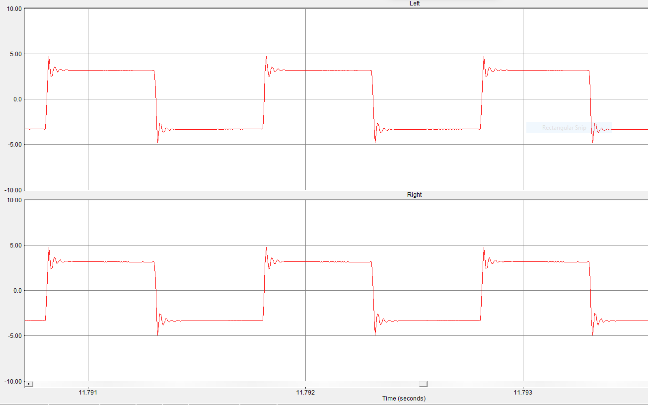
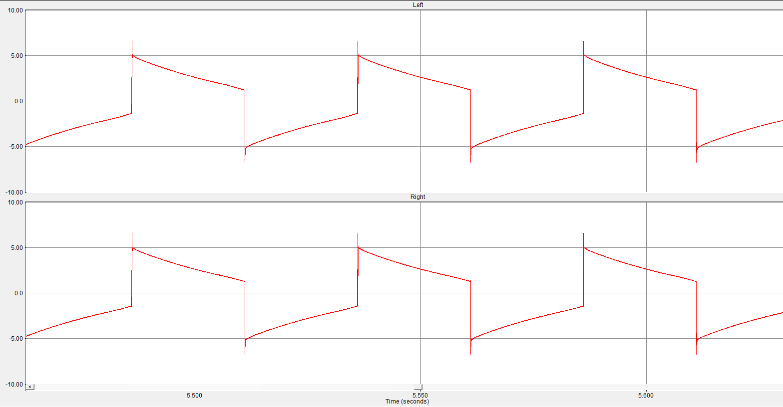
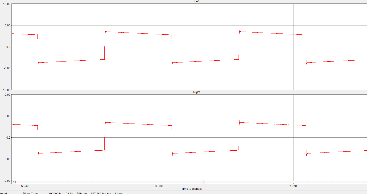
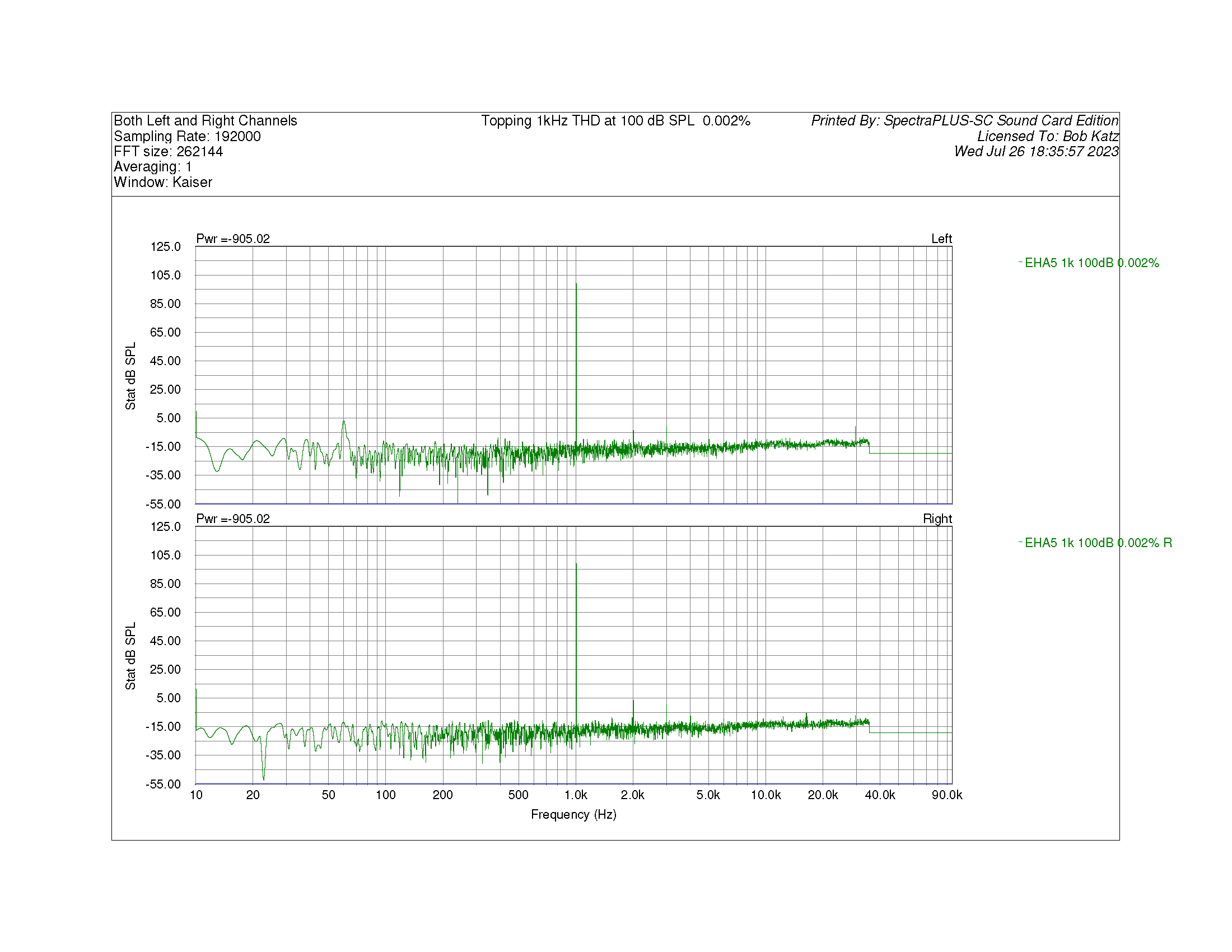
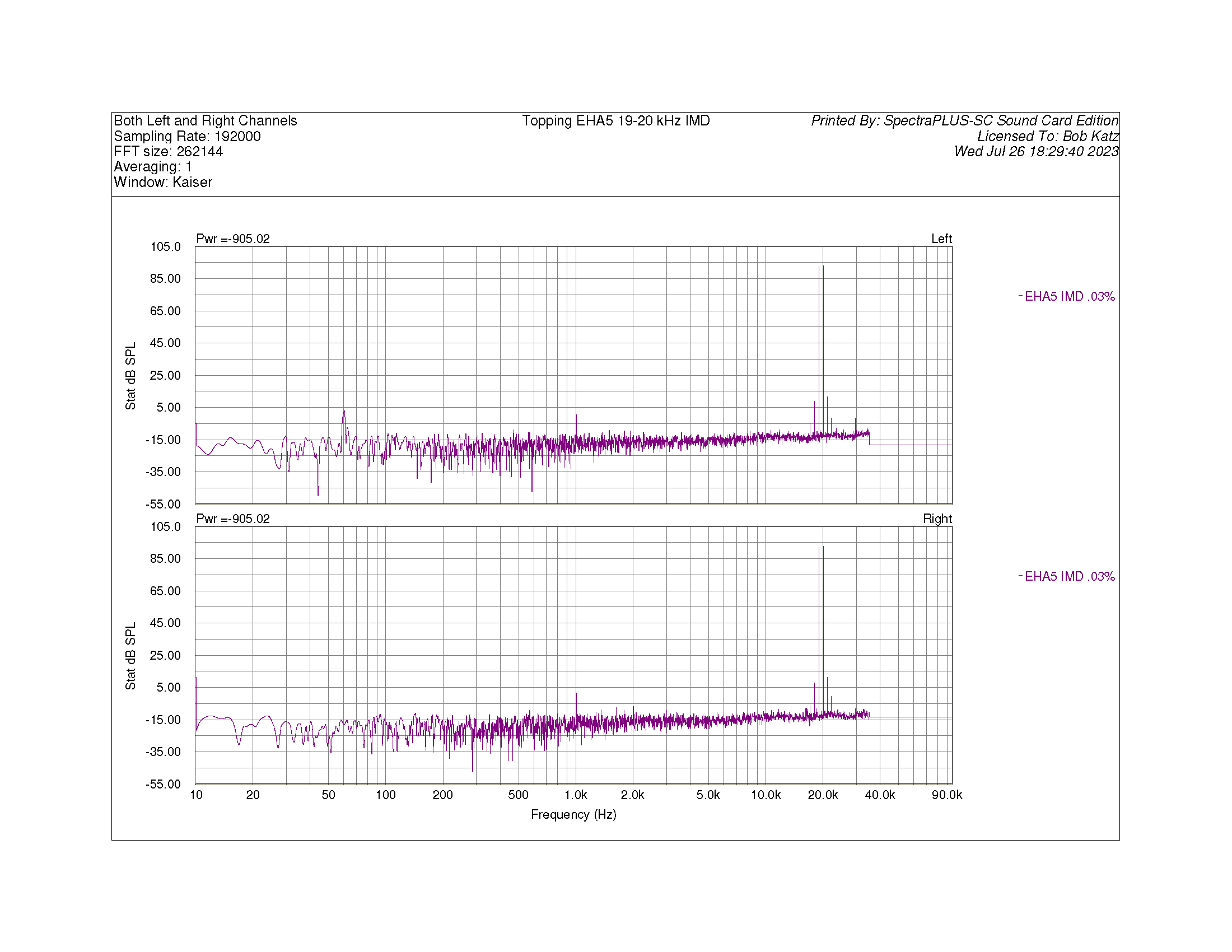
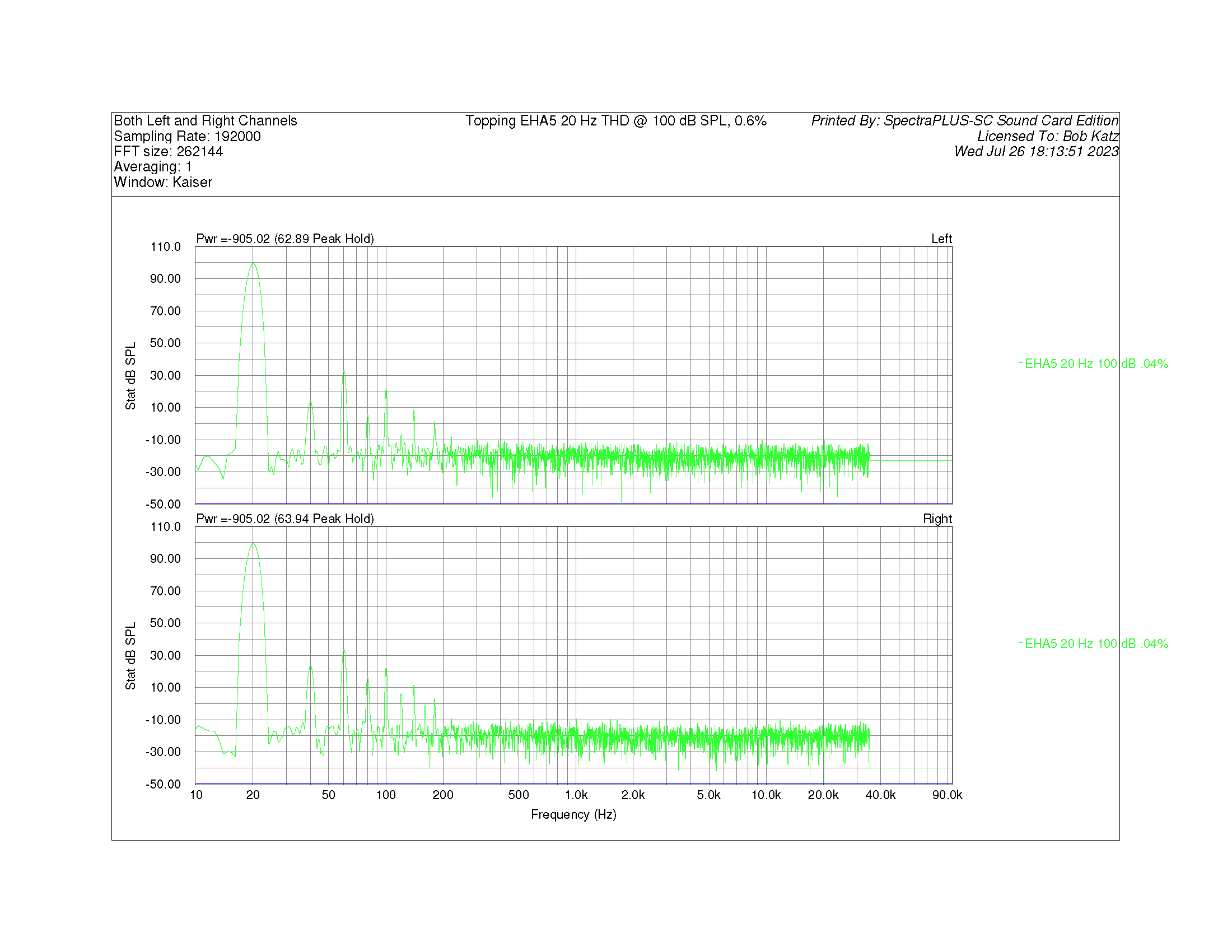
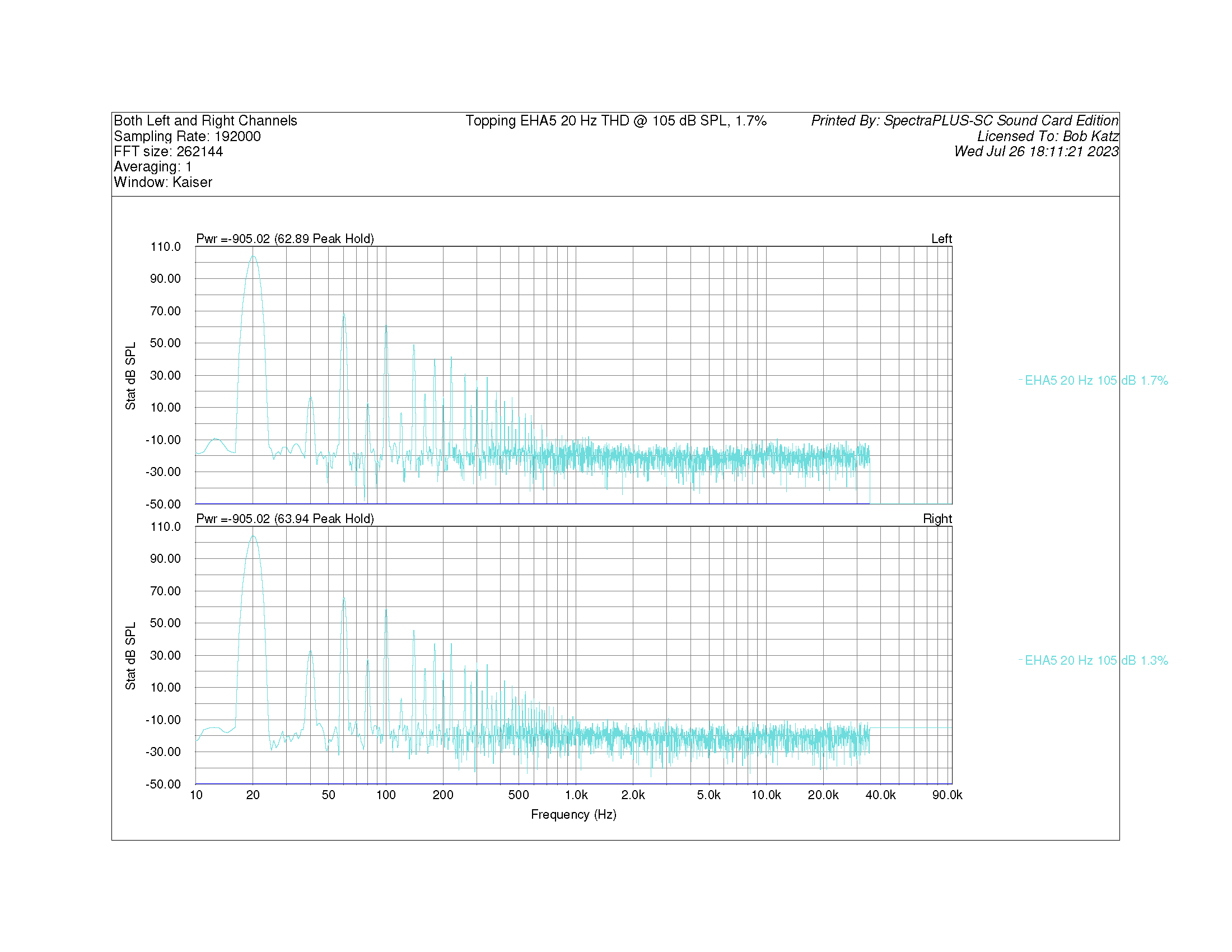
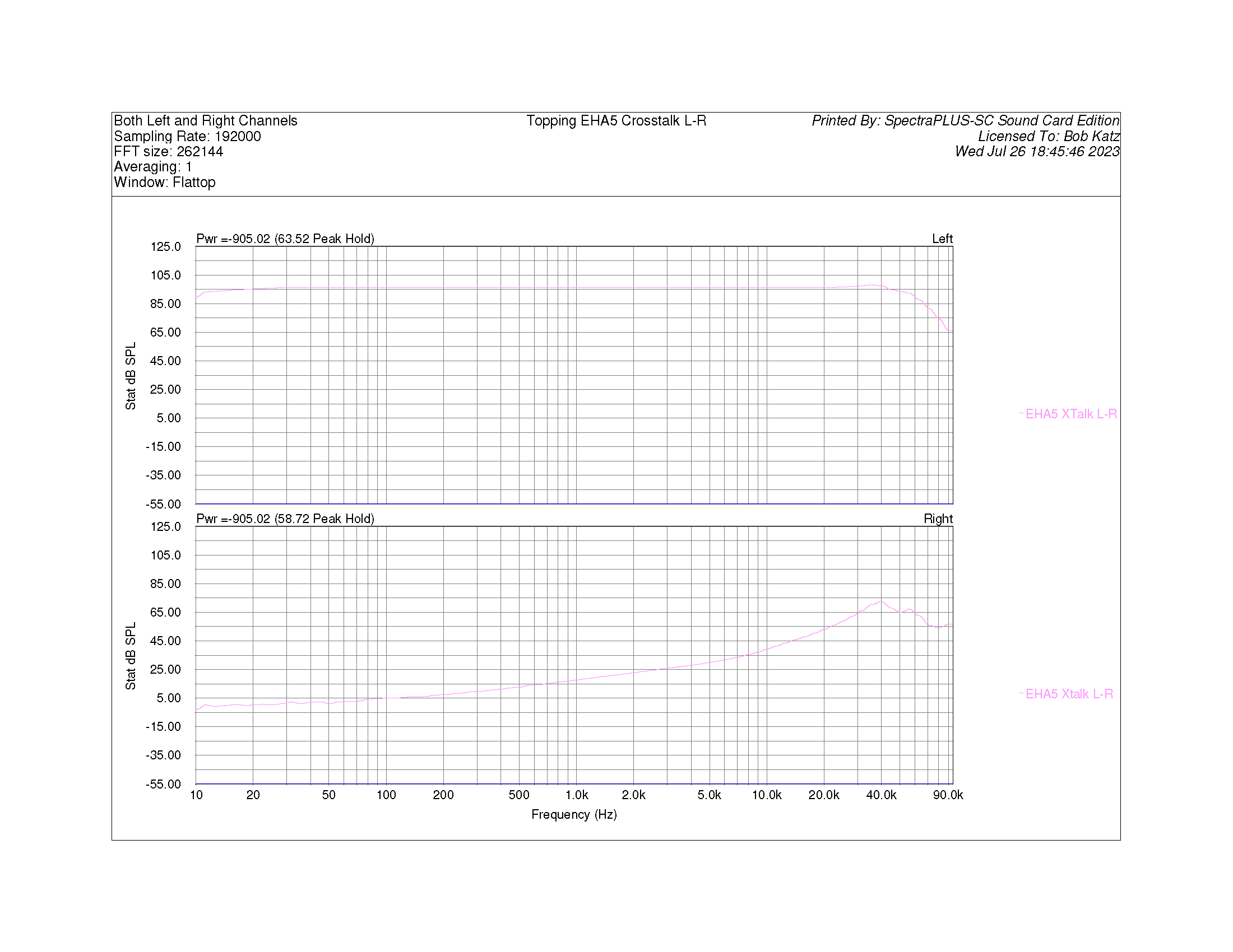
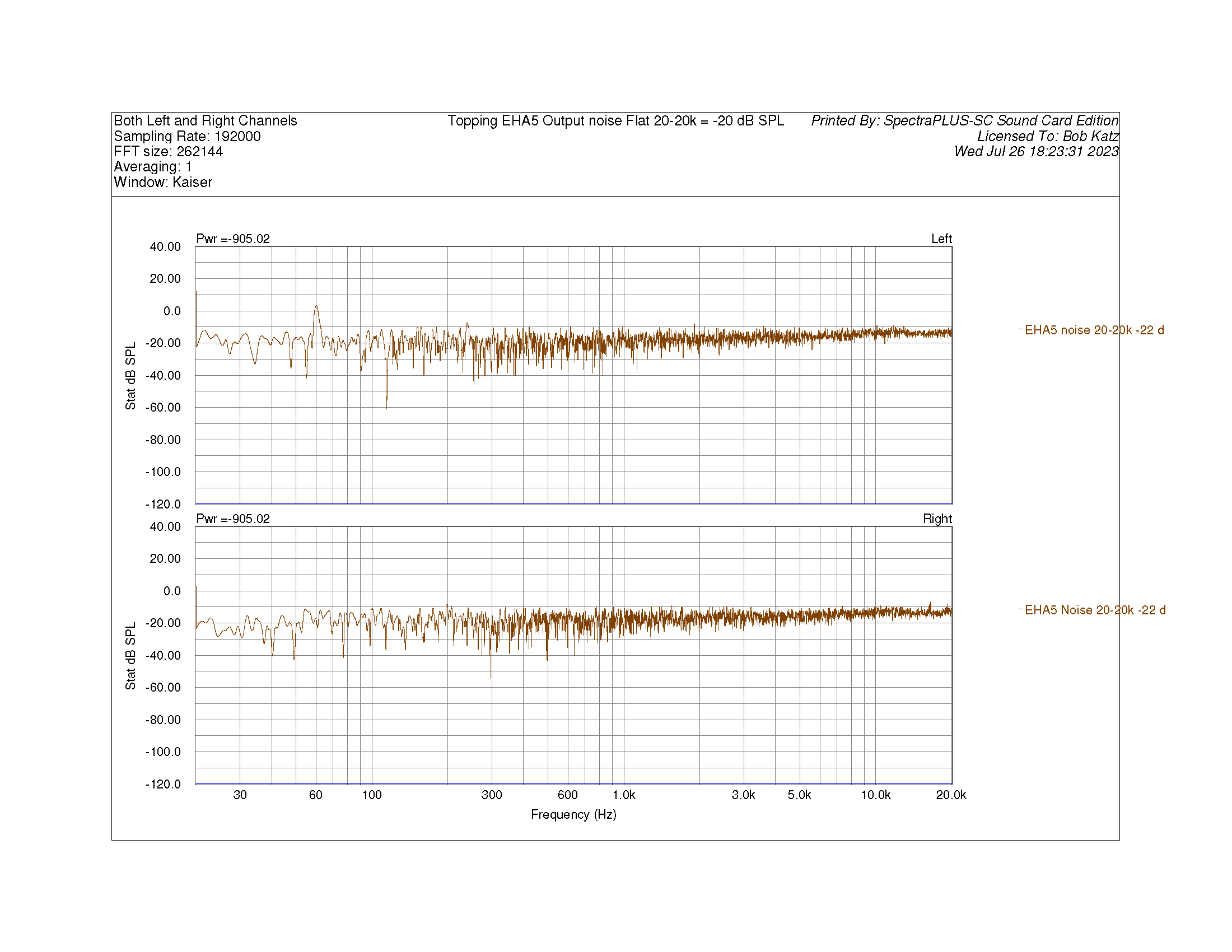
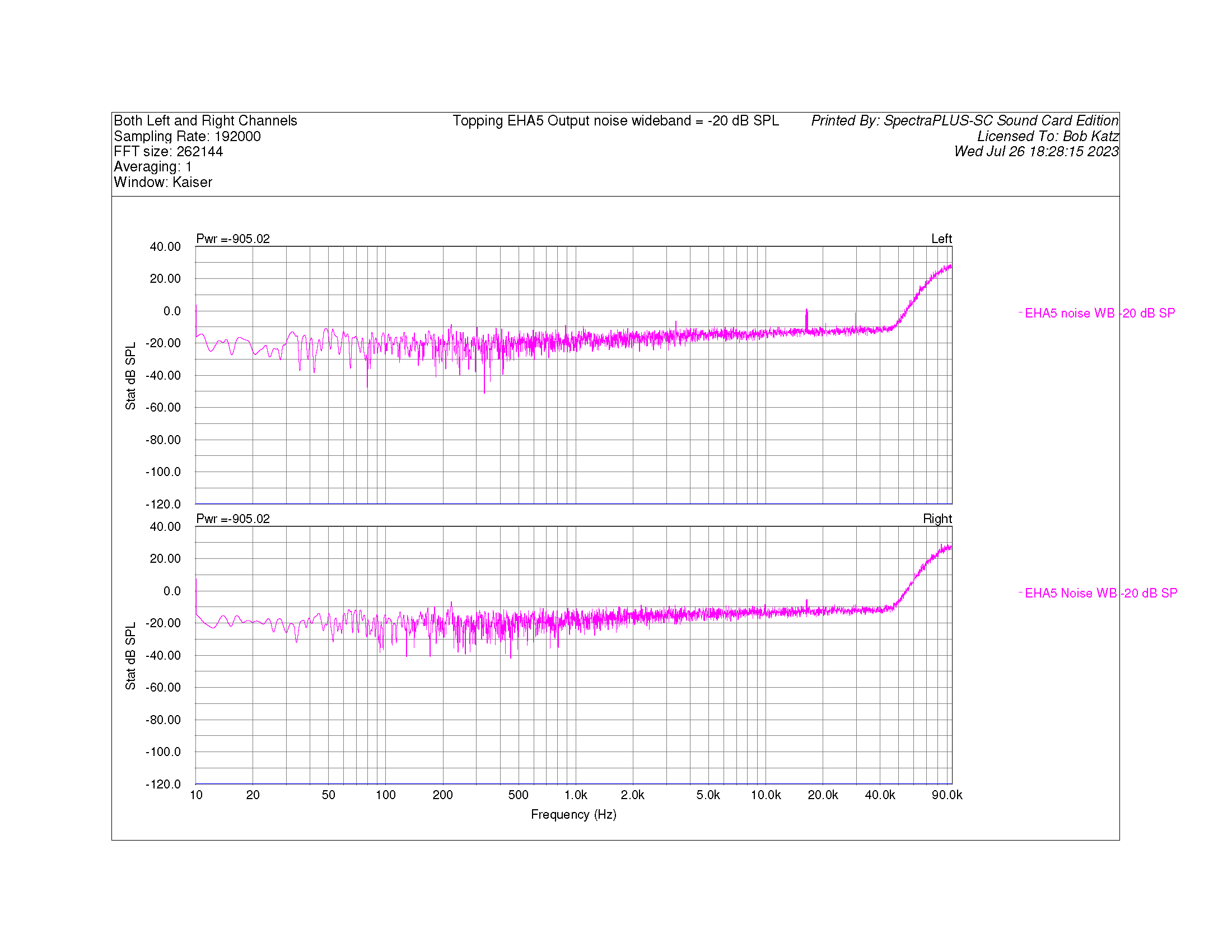
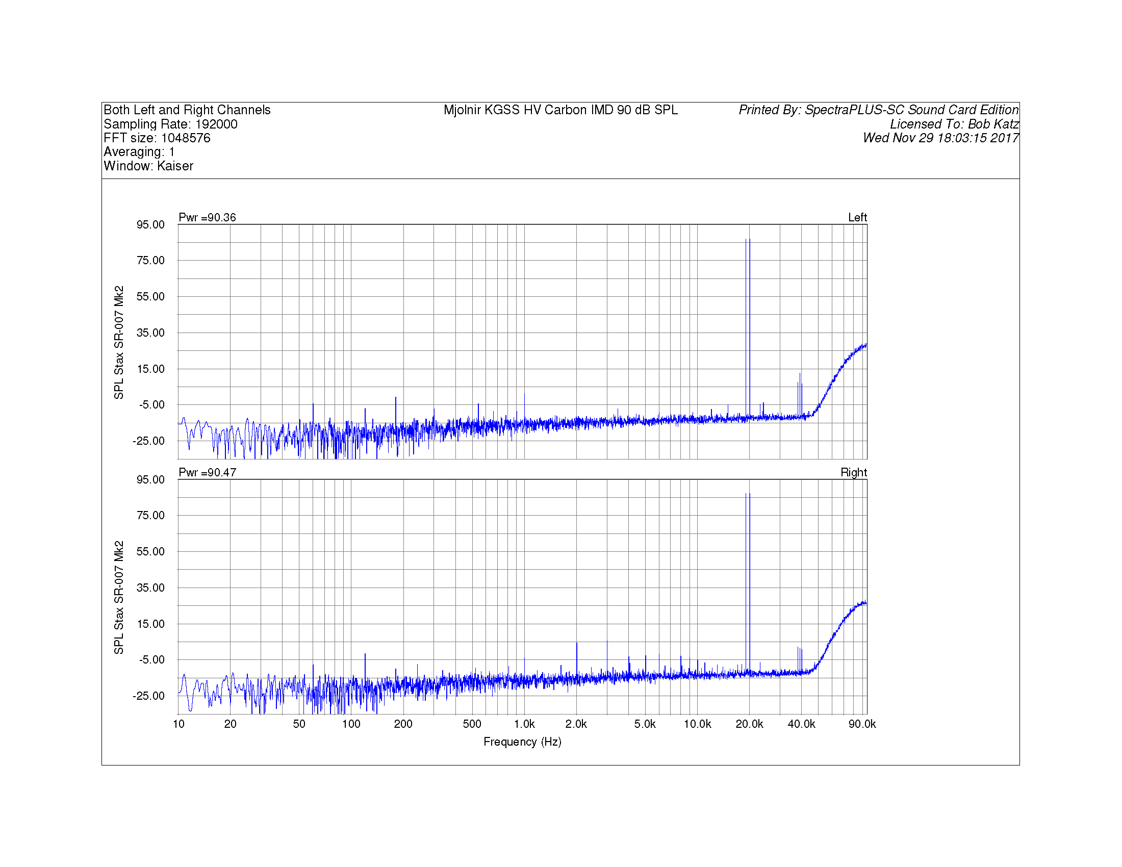
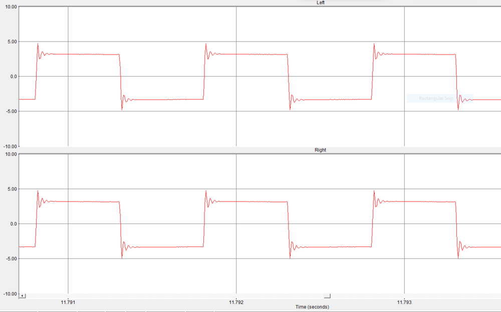
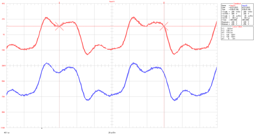
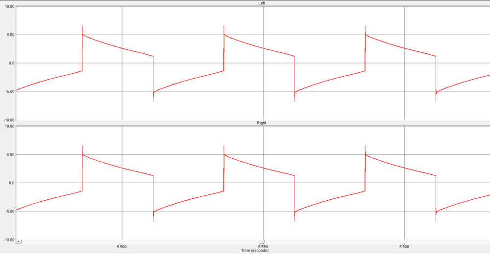
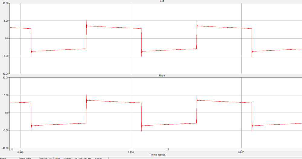
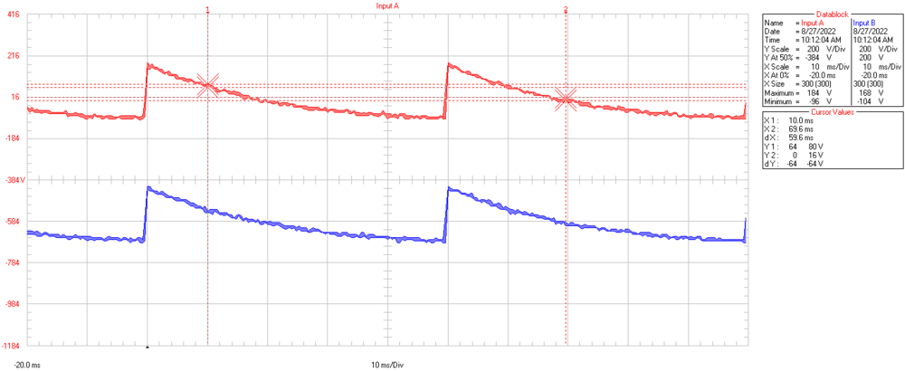
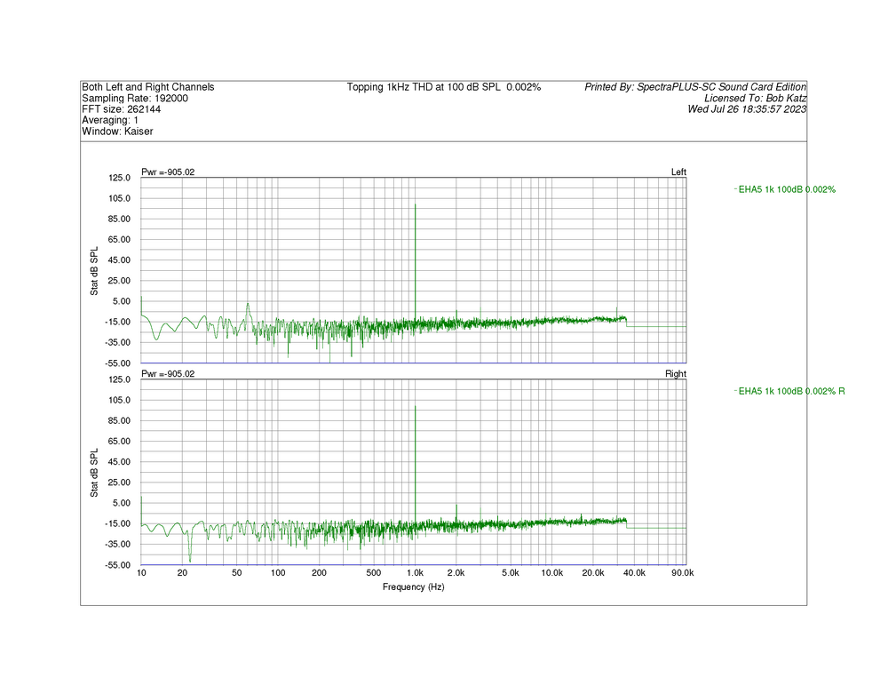
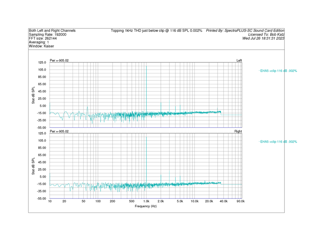
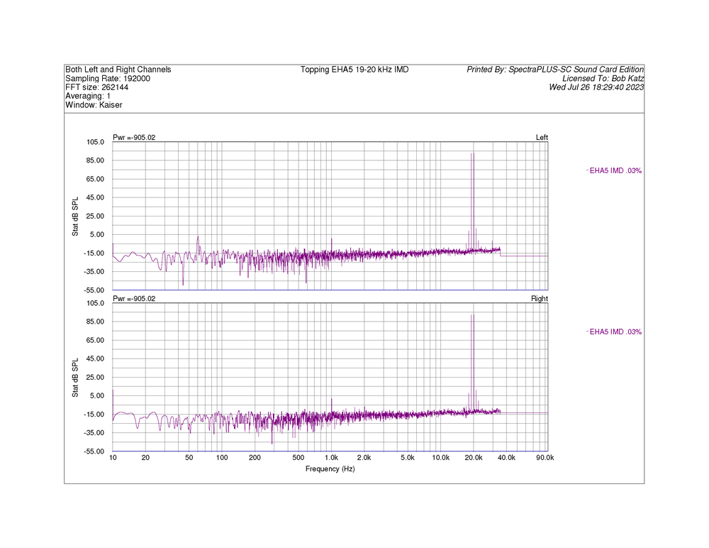
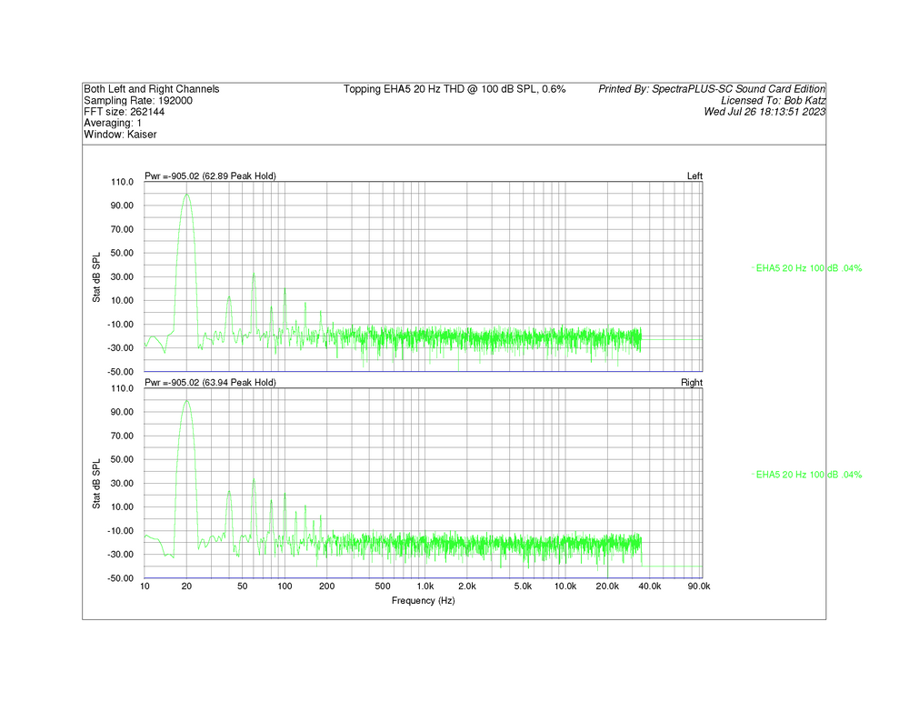
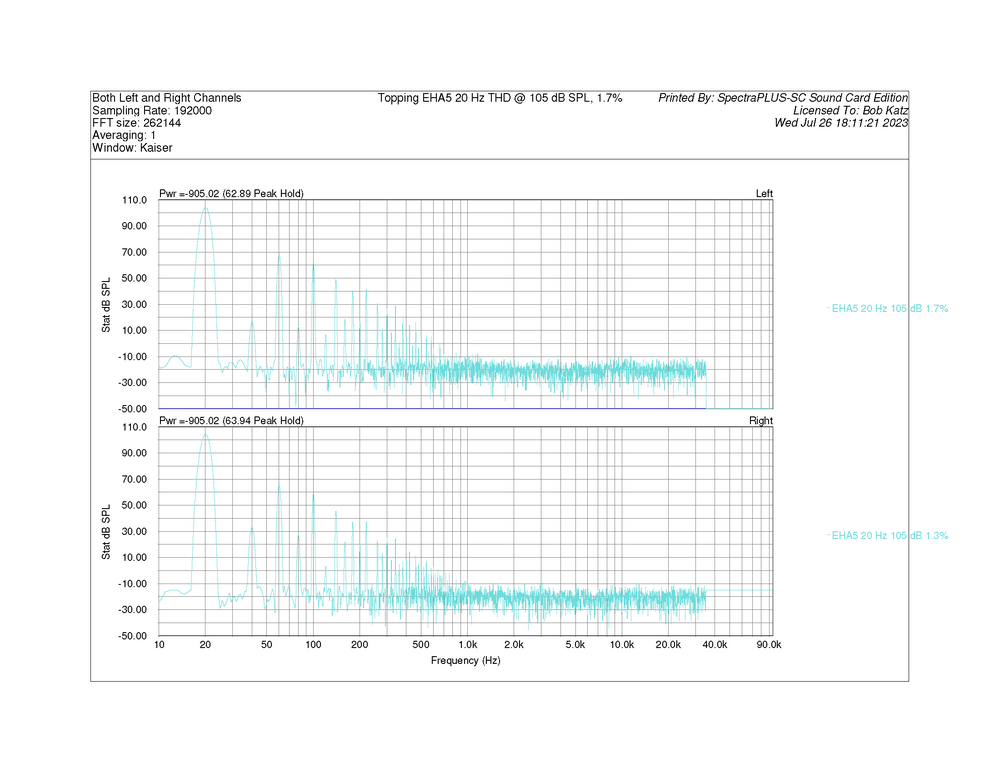
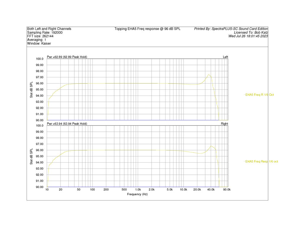
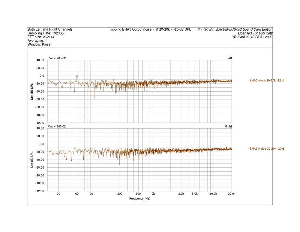
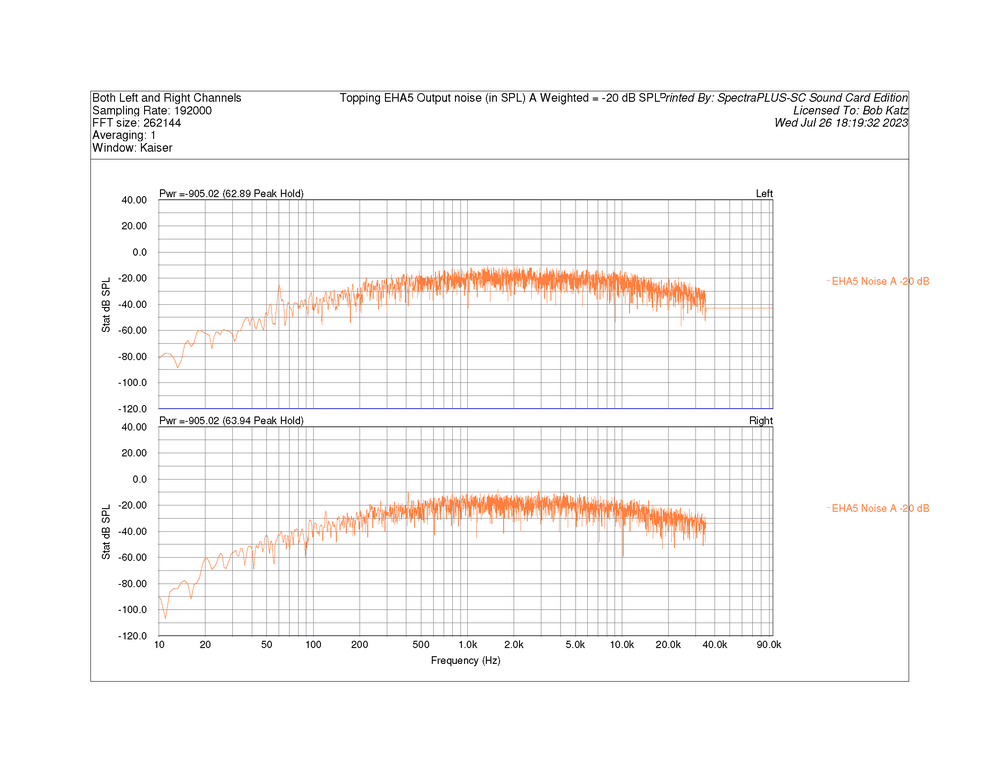
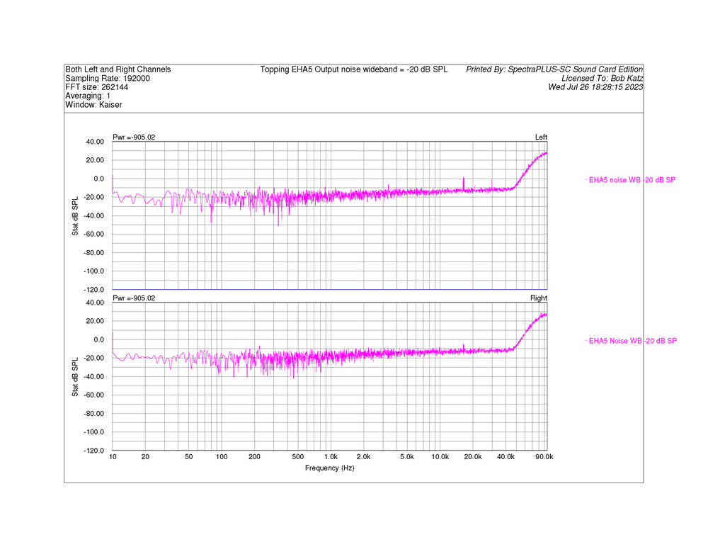
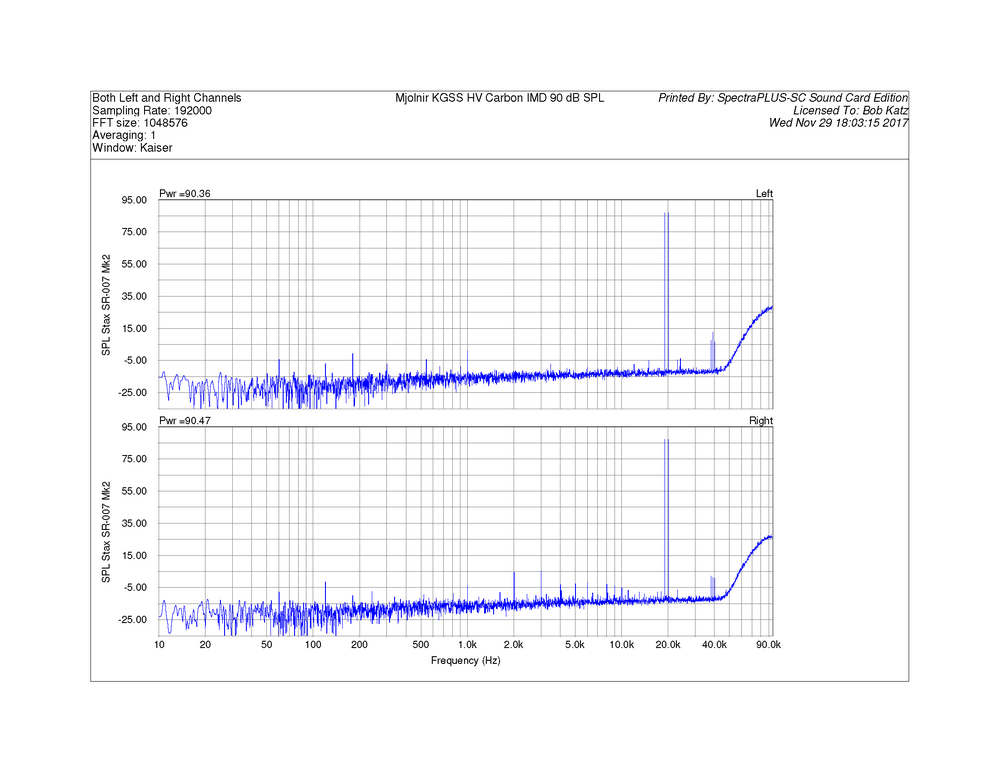
1 pointI bought the Topping and got it this week, with hopes it could be a second or extra Stat amp. I was even planning on doing a "bargain stat amp" feature at my new journalistic home "Positive Feedback", where you can find my review of the Audeze CRBNs, for example. Anway, I'm not going to publish, I don't like to publish reviews of bad gear 😞 What a disappointment this amp turned out to be. My disappointment came in stages. The first stage was an optimistic listen: "Hey, not too bad". At that time I was listening to some simple classical and folk arrangements: with solo voices and guitar, the weaknesses of the Topping circuit are not immediately obvious. But as soon as I played more complex music, full orchestra, rock band, you name it. Where it starts to get real harsh, bloated, lose dimension is with complex music, full orchestra, rock band, you name it. The more I listened, the more I started to hate this amp. I WILL BET THAT THERE ARE MEASUREMENTS THAT WILL REVEAL THIS AMP'S WEAKNESSES. You just have to know how to find out where the bodies are buried. I did find some that clearly show its weaknesses. Attached below. Frequency response (with a 100 pf load), Output level just before clipping, THD at various frequencies at normal levels and just before clipping (spectrum and %), IMD (19-20 kHz) (spectrum and %). The one thing I should have measured is a special multitone signal I use, I bet that would show where the bodies are buried, and tell us why the amp falls totally flat the more complex the music you put into it. But I'm so disenheartened and disappointed by the sound of it that I don't have the energy to bring it back to the test bench. I like to display an amplifier's measurements in equivalent SPL, based on Stax 007 and CRBN nominal sensitivity of 100 volts RMS = nominally 100 dB SPL. It helps bring a real-world perspective to amplifier measurements. Topping Factory spec for max is 700 volts RMS (I suppose the factory took this a cat's hair below clipping and only at 1 kHz). I measured maximum output at 1 dB below clipping at 630 volts RMS at 1 kHz, equivalent to 116 dB SPL. But When performing the 20 Hz THD test, the amp's DC protection circuit kicked in and the most I could get out of it at 20 Hz with a continuous sine wave was the equivalent of 105 dB SPL, 177 volts RMS before the amp shut down. So the lower the frequency, the worst the amp's headroom for transients. Plus, the THD at low frequencies is pretty bad, the transformer saturates very strongly. To see where the skeletons are buried in this amp, take a look at my measurements. The measurements to really study is a comparison of the Mjolnir KGSS HV Carbon and the Topping at nominally 90 dB equivalent SPL of IMD 19-20 kHz 1:1 ratio. I think that lurking in that measurement is at least one of the reasons why the Topping sounds so harsh and the Mjolnir sounds so pure. The primary difference tone at 1 kHz in the spectrum does not tell the story. Notice the high frequency side bands near the 19-20 kHz that begin to reveal to us the Topping's nonlinearities. There's more in the attachments. I'm sorry that I didn't do the multitone, I will some day, when I get around to it, and I'm sure it will reveal the skeleton underneath the "golden glow" of this amp. The date in the Fluke scope pictures is wrong... it's actually yesterday, 7/28/23. I have to fix the date in my Fluke Scope. Every time the battery dies, it loses the date 😞

 1 point
 -
Oh dear. Today has been one of bad discoveries. First off, the 5D IV is running ancient firmware. After much banging of head against various objects, I managed to go from 1.17 to 1.4. I still cannot get the (gosh darn) Canon EOS utility for MacOS to connect to the 5D via USB. I was able to connect the 5D to my WiFi network and get things working that way. While all of the above has been stressful and headache inducing, it pales in comparison to this afternoon's discovery. Since yesterday I have tried every single one of my many CF cards with the 5D. It has rejected all of them. At first I wasn't too surprised as my CF cards are old and older. My cranky old 30D doesn't like most of them. My ID 5D classic is less picky. I now know why the 5D IV doesn't like any of them: It has a bent bin. The paste eating absolute chucklefuck previous owner shoved a card in the wrong way and either never noticed or never told anyone. I'm now weighing my options about whether or not I want to keep this camera. I still have not successfully gotten app that will report the camera's shutter actuation count. It's looking like I'm going to have to pursue that on (shudder) Windows.0 points
-
0 points
(2).jpg.95471642d8723baf91c5444e39df11e7.jpg)