

Leaderboard


Popular Content
Showing content with the highest reputation on 01/26/19 in all areas
-
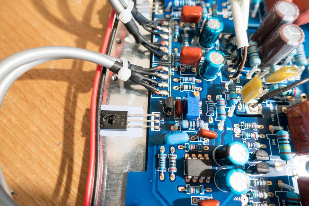
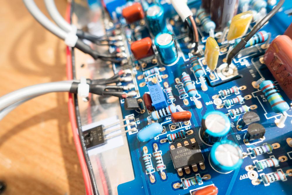
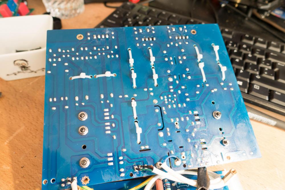
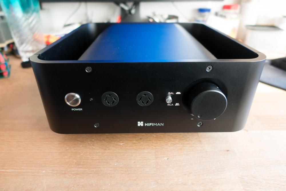
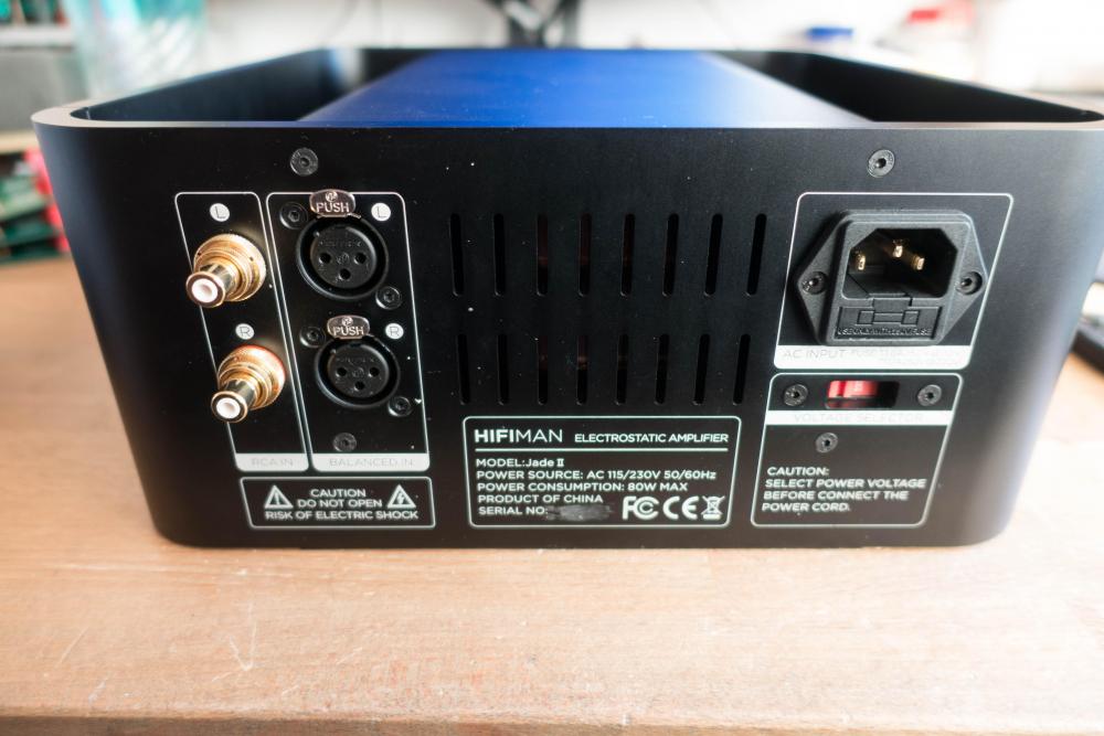
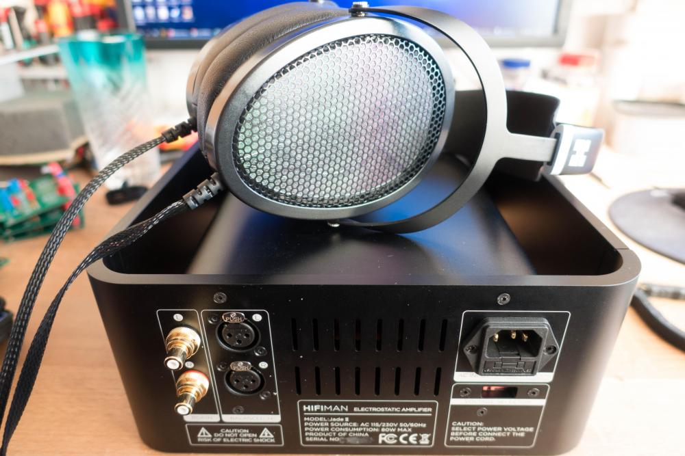
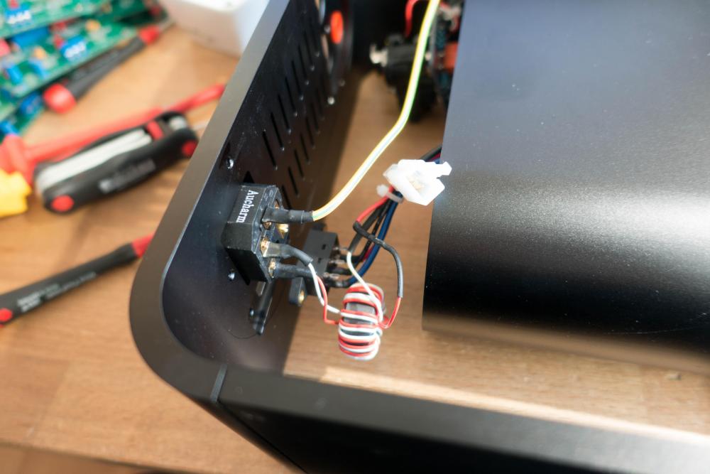
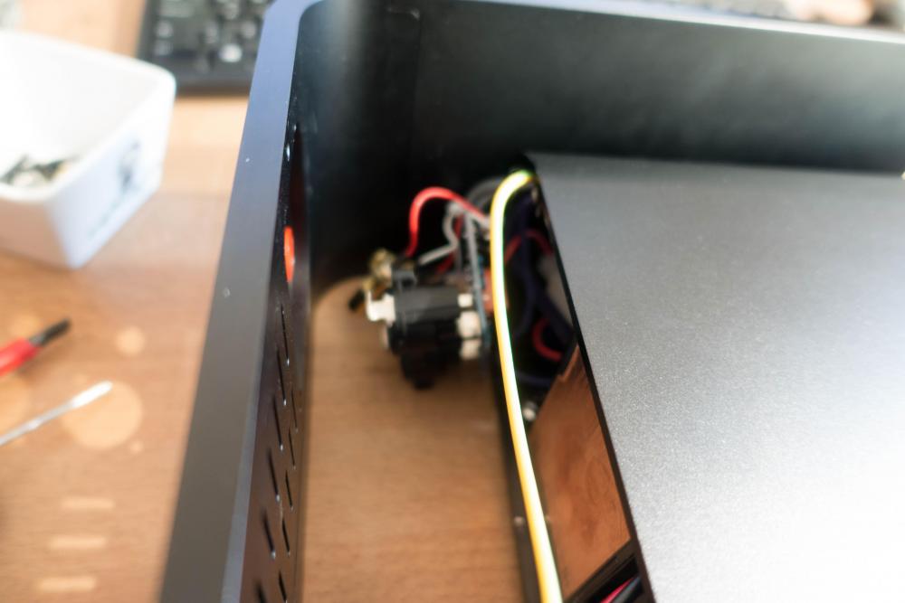
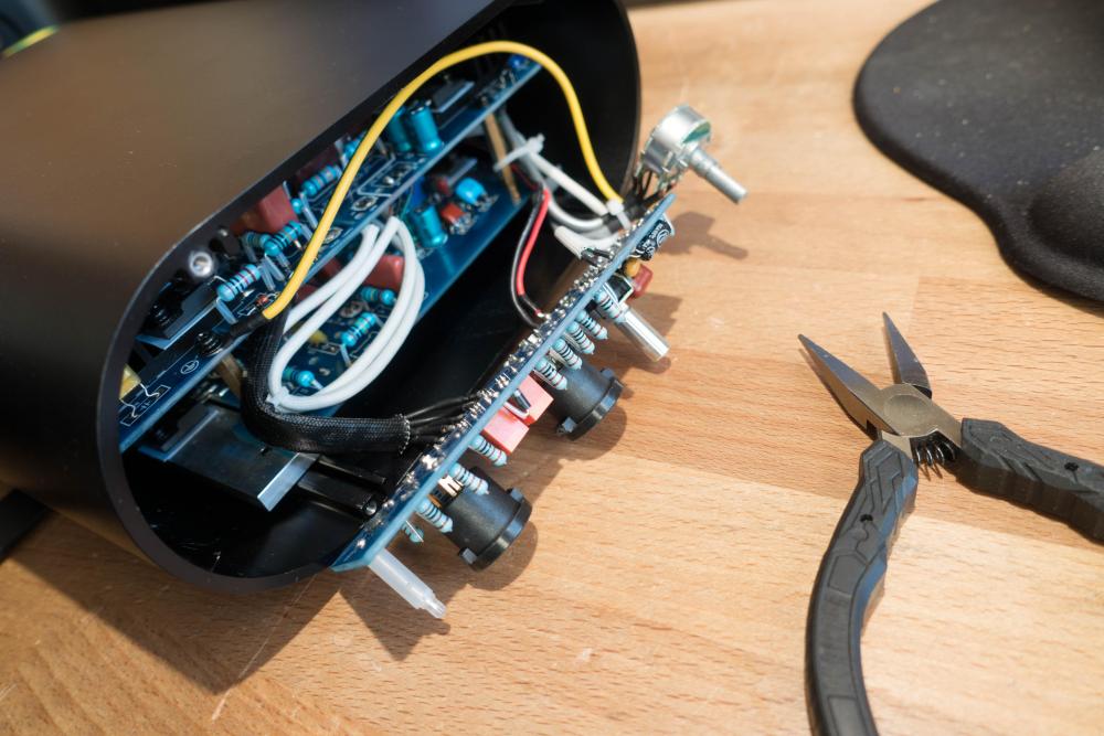
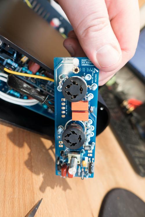
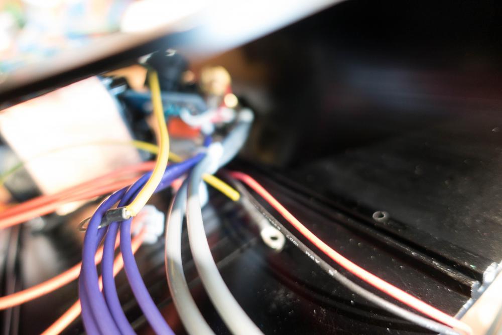
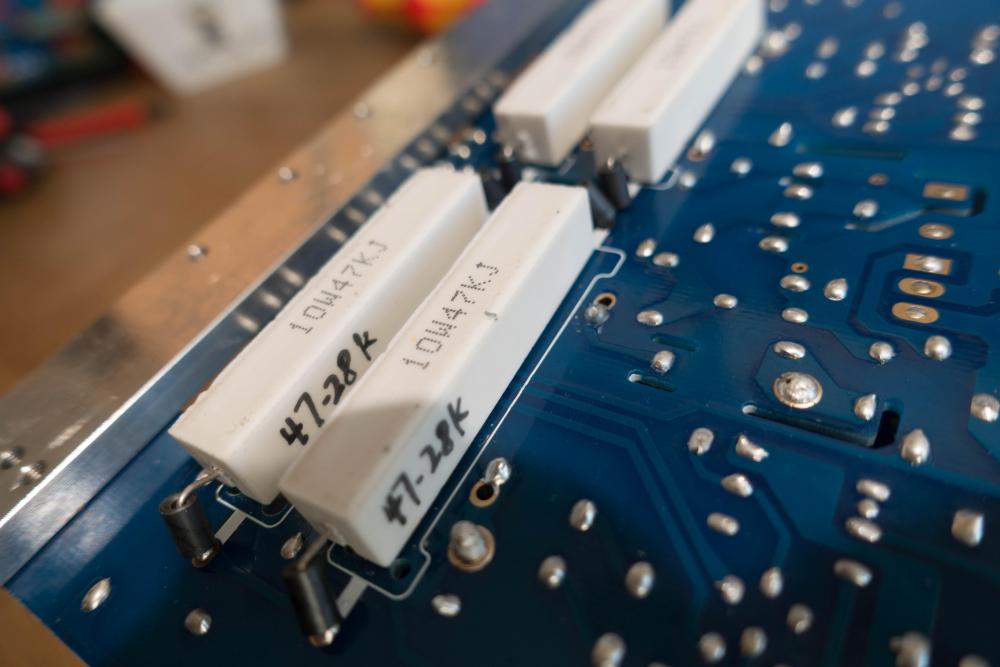
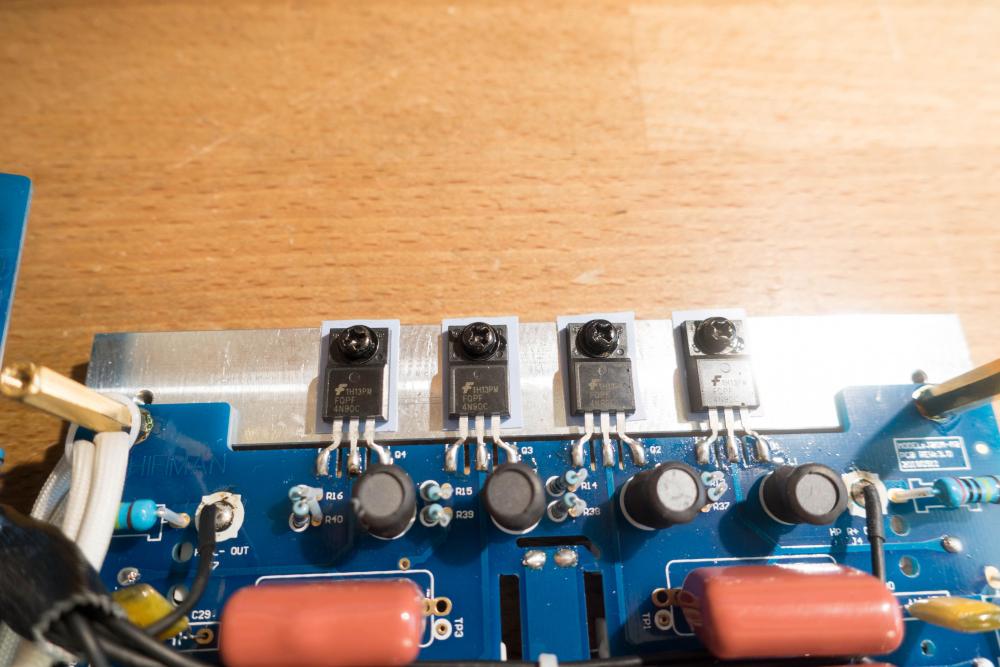
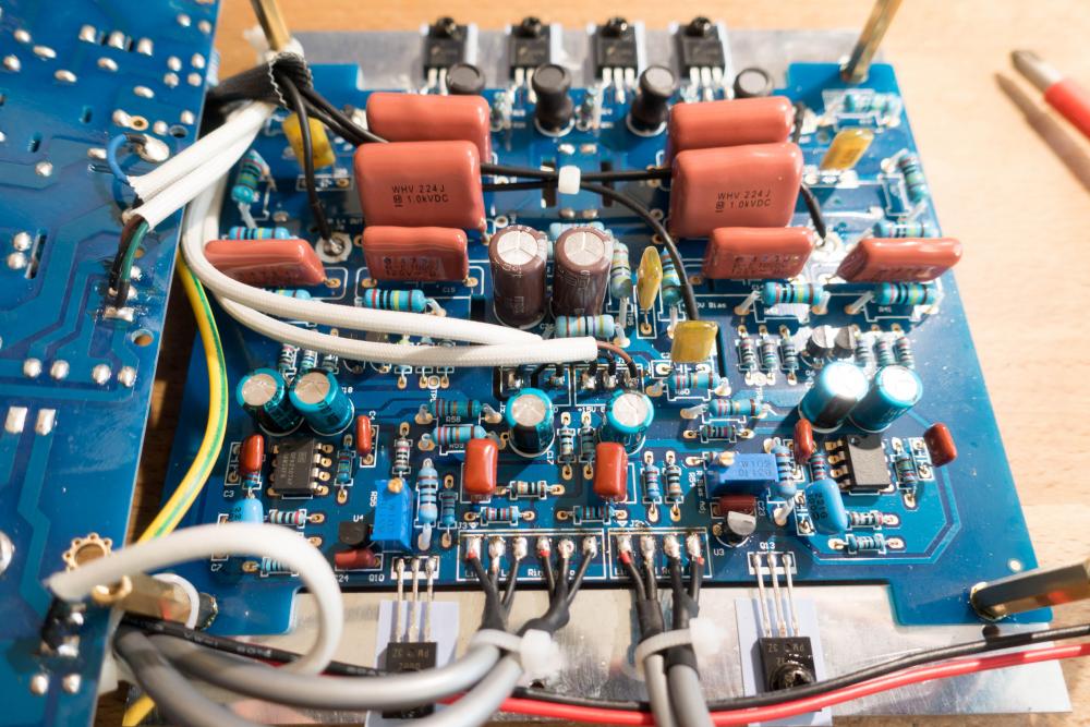
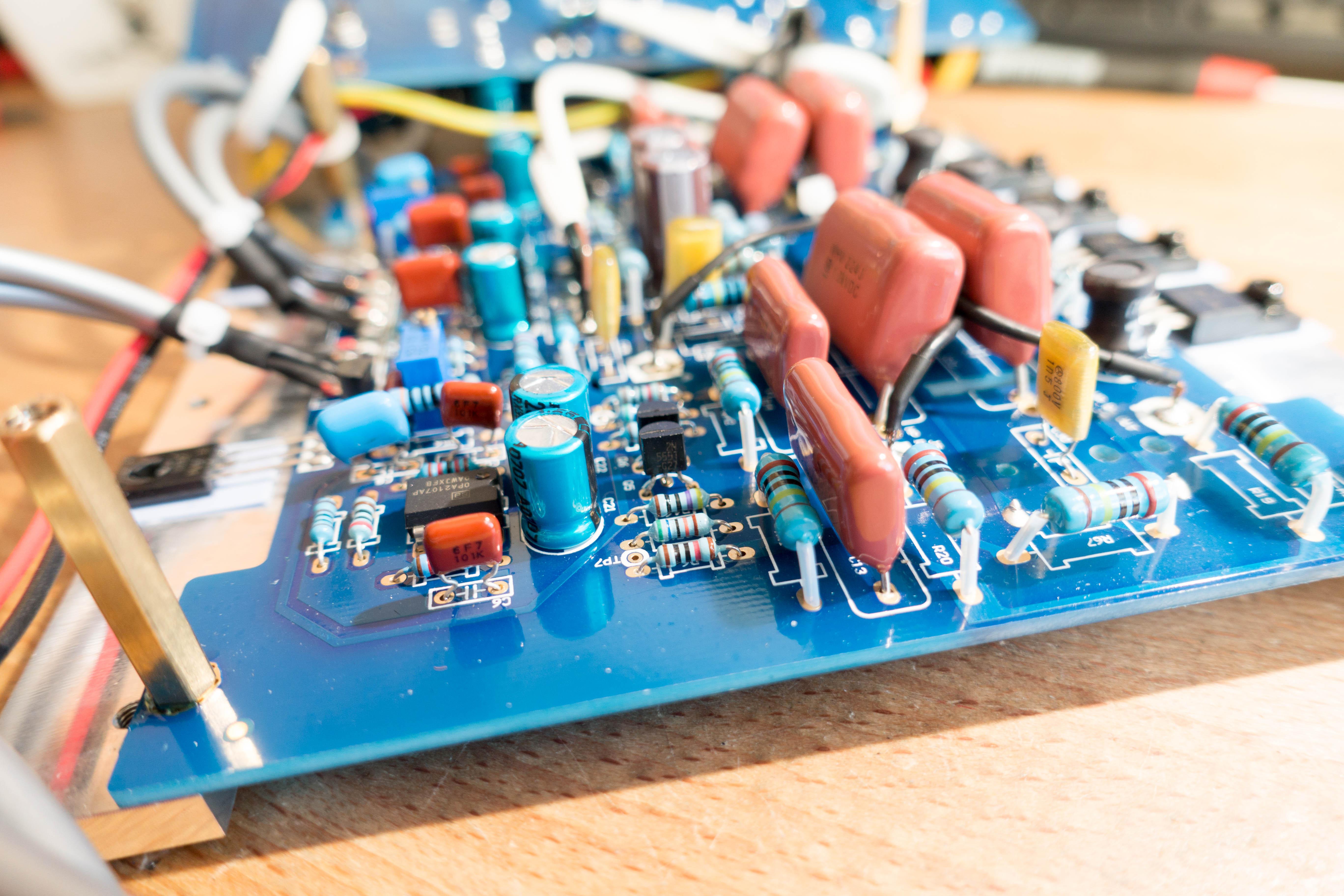
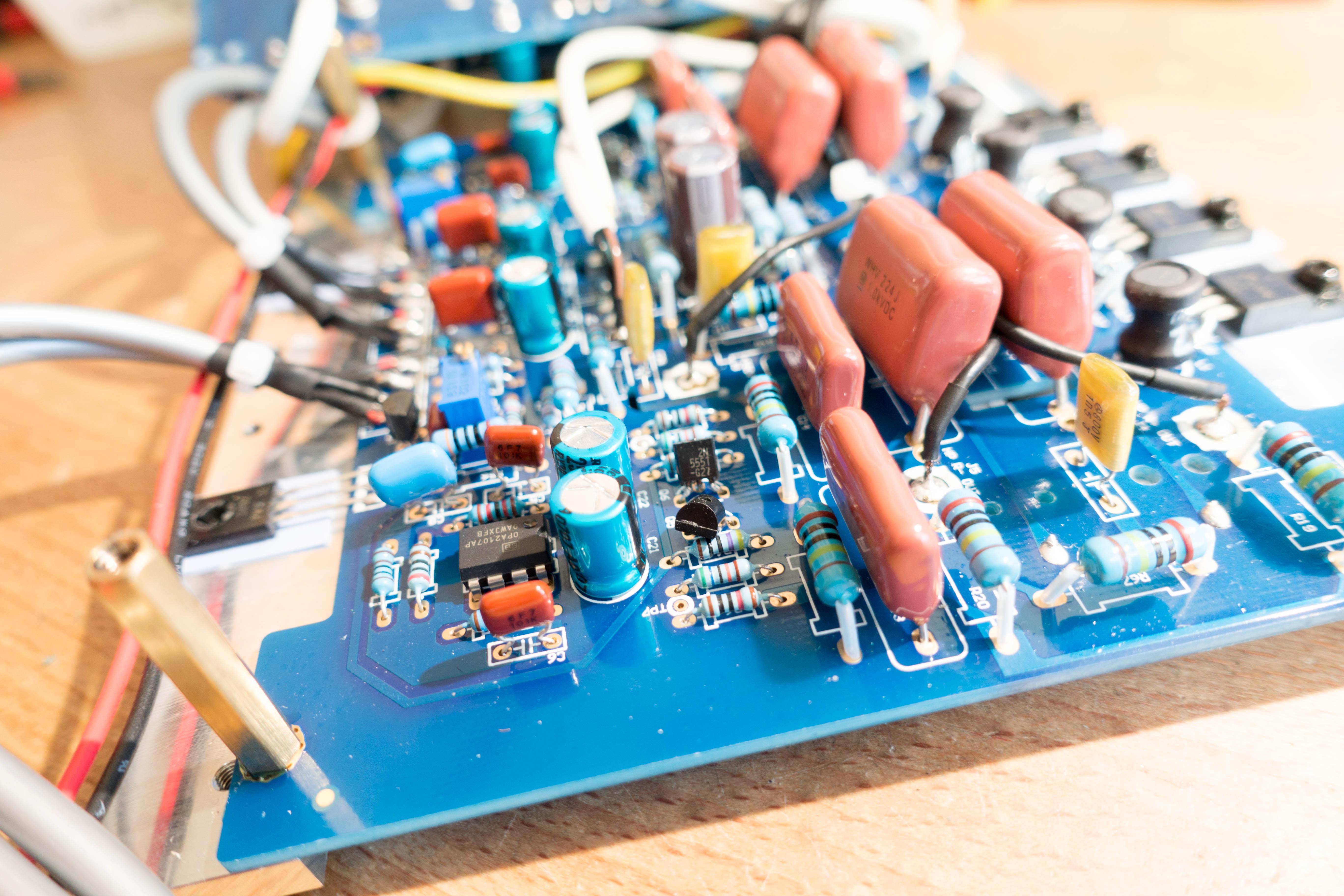
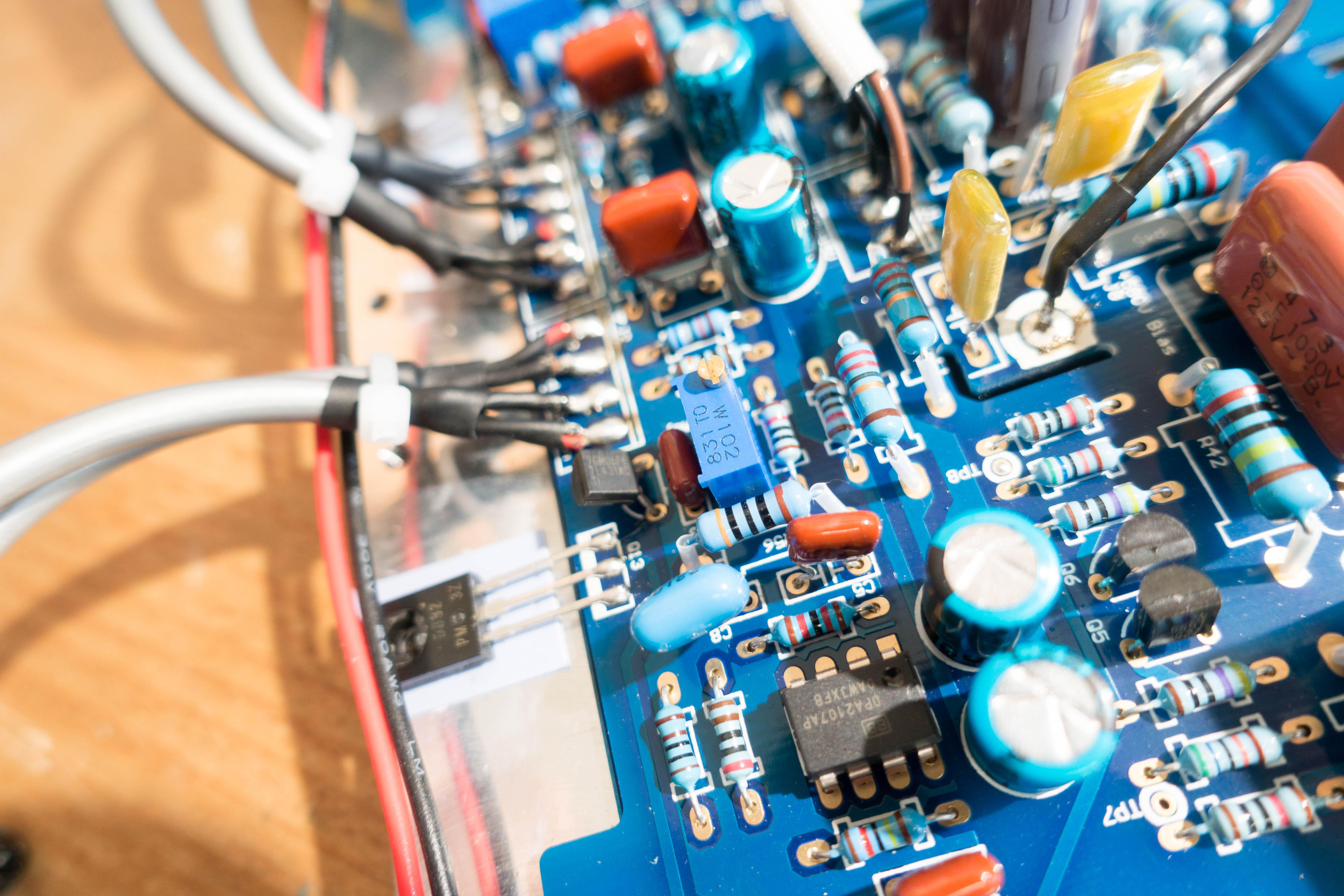
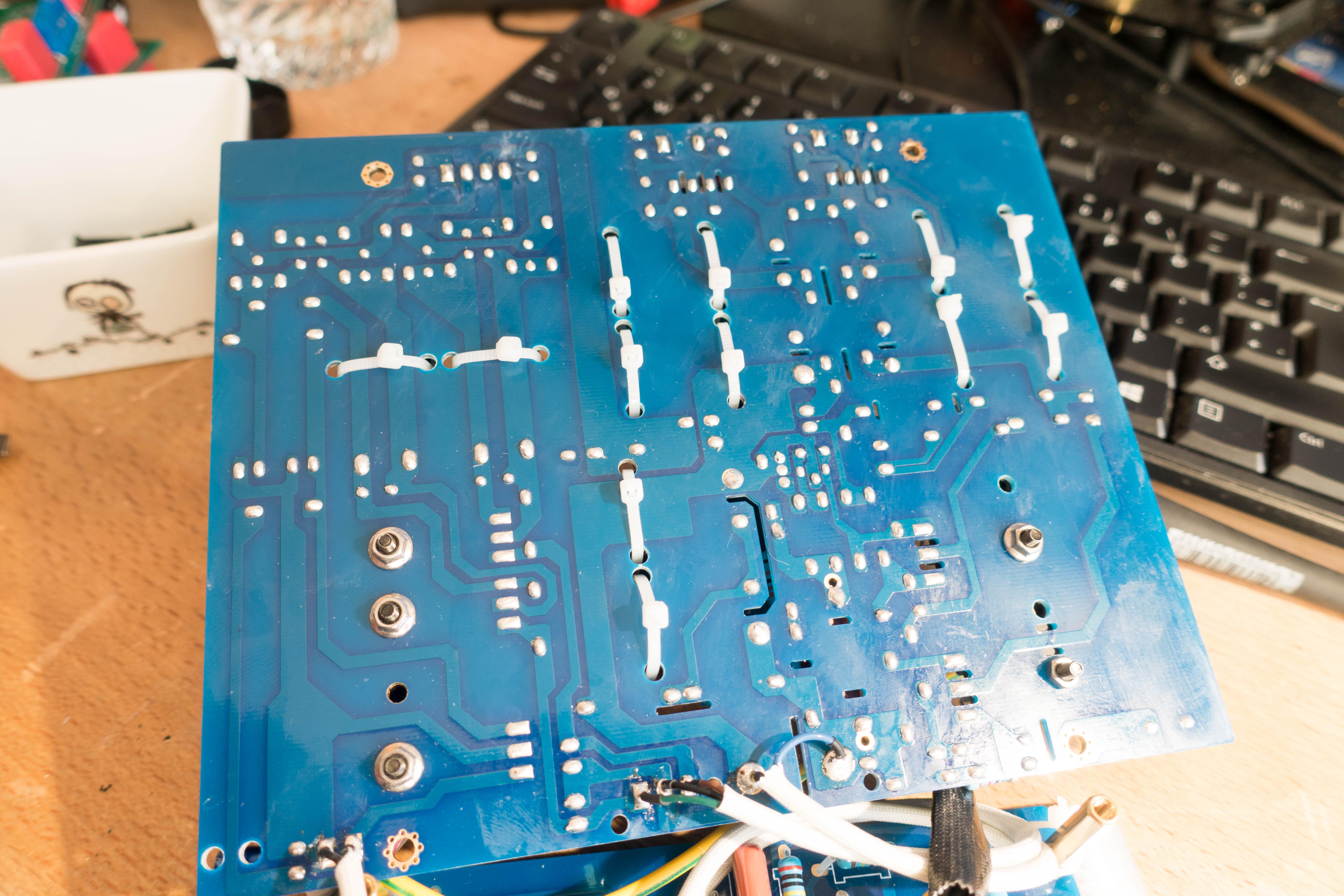
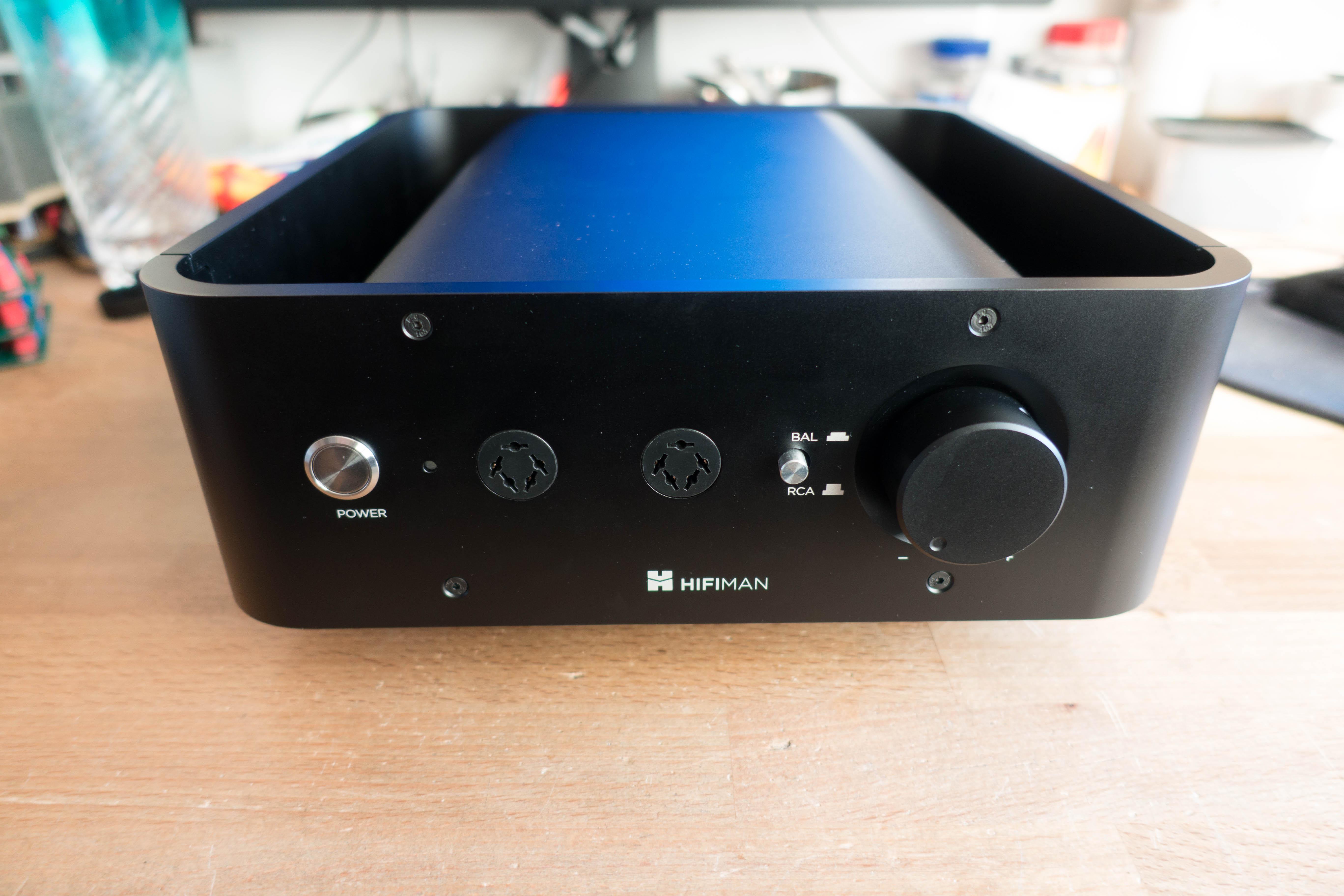
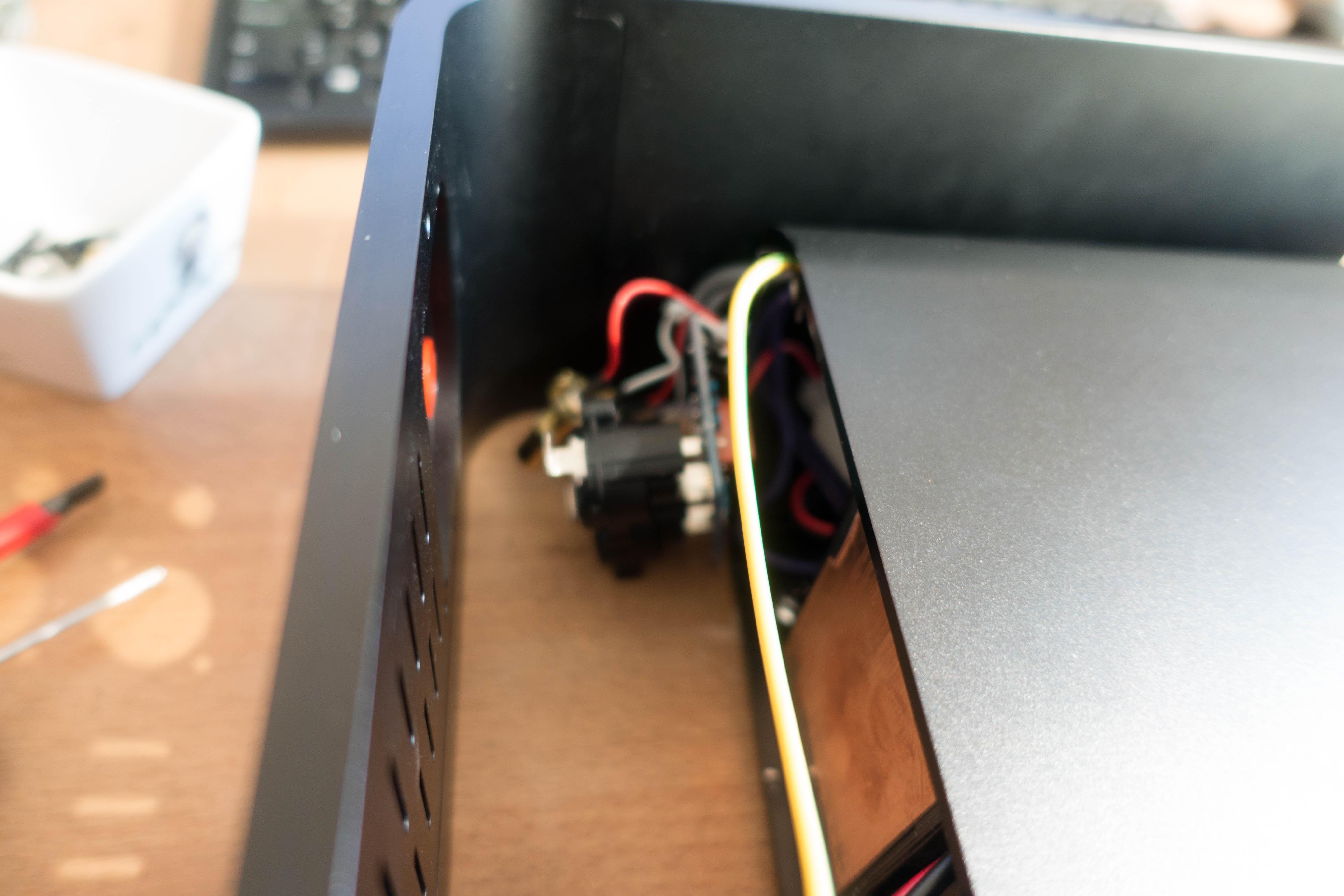
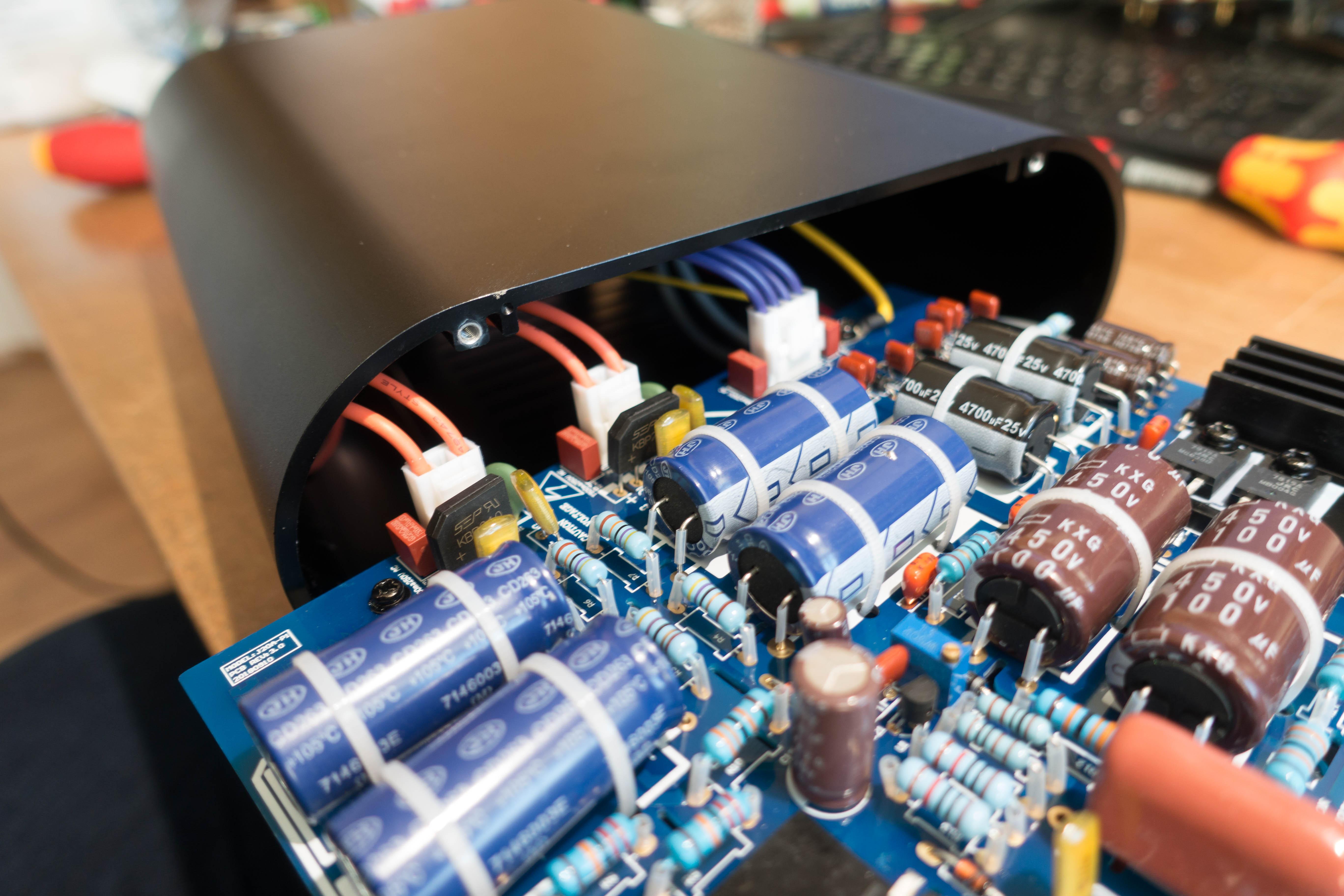
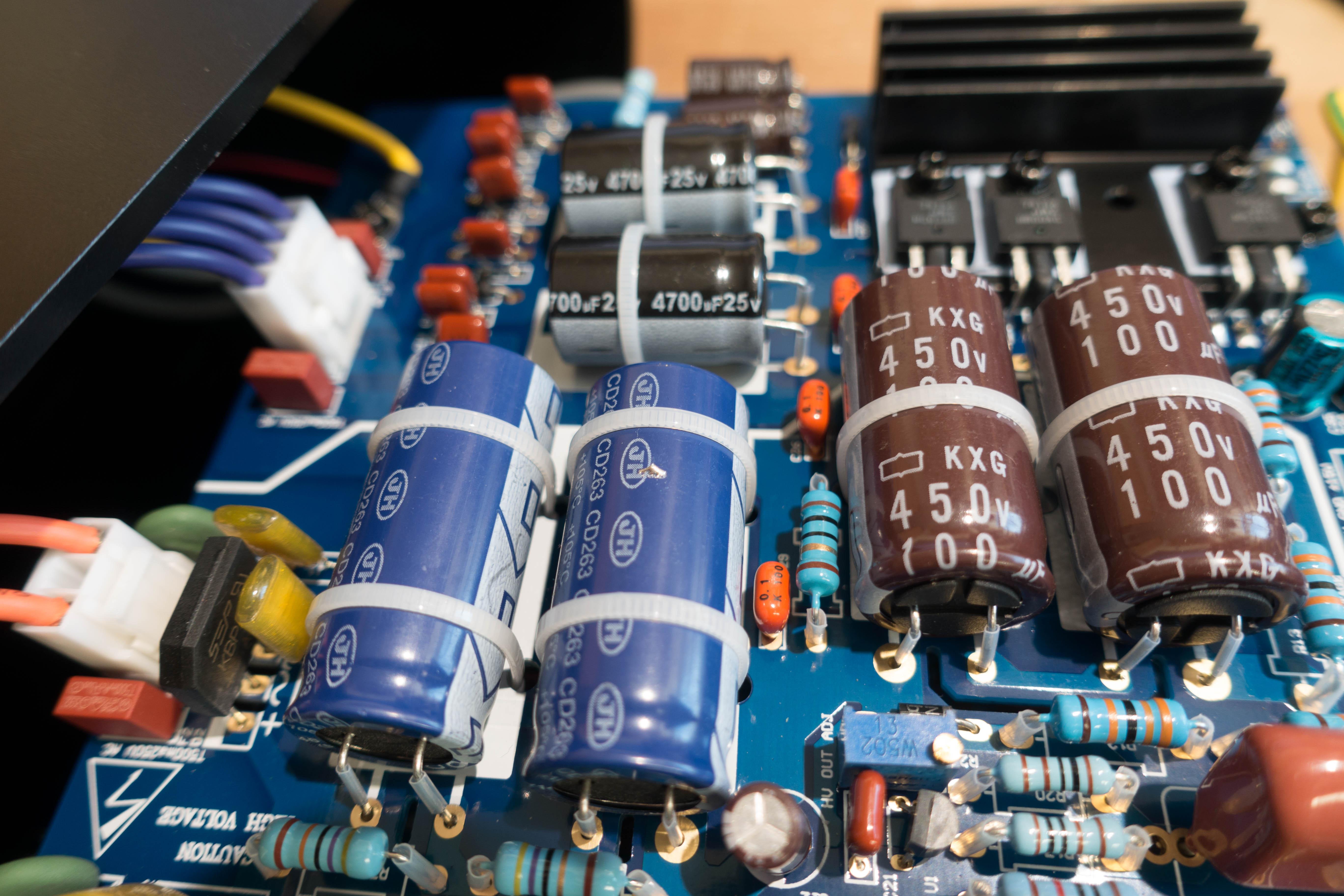
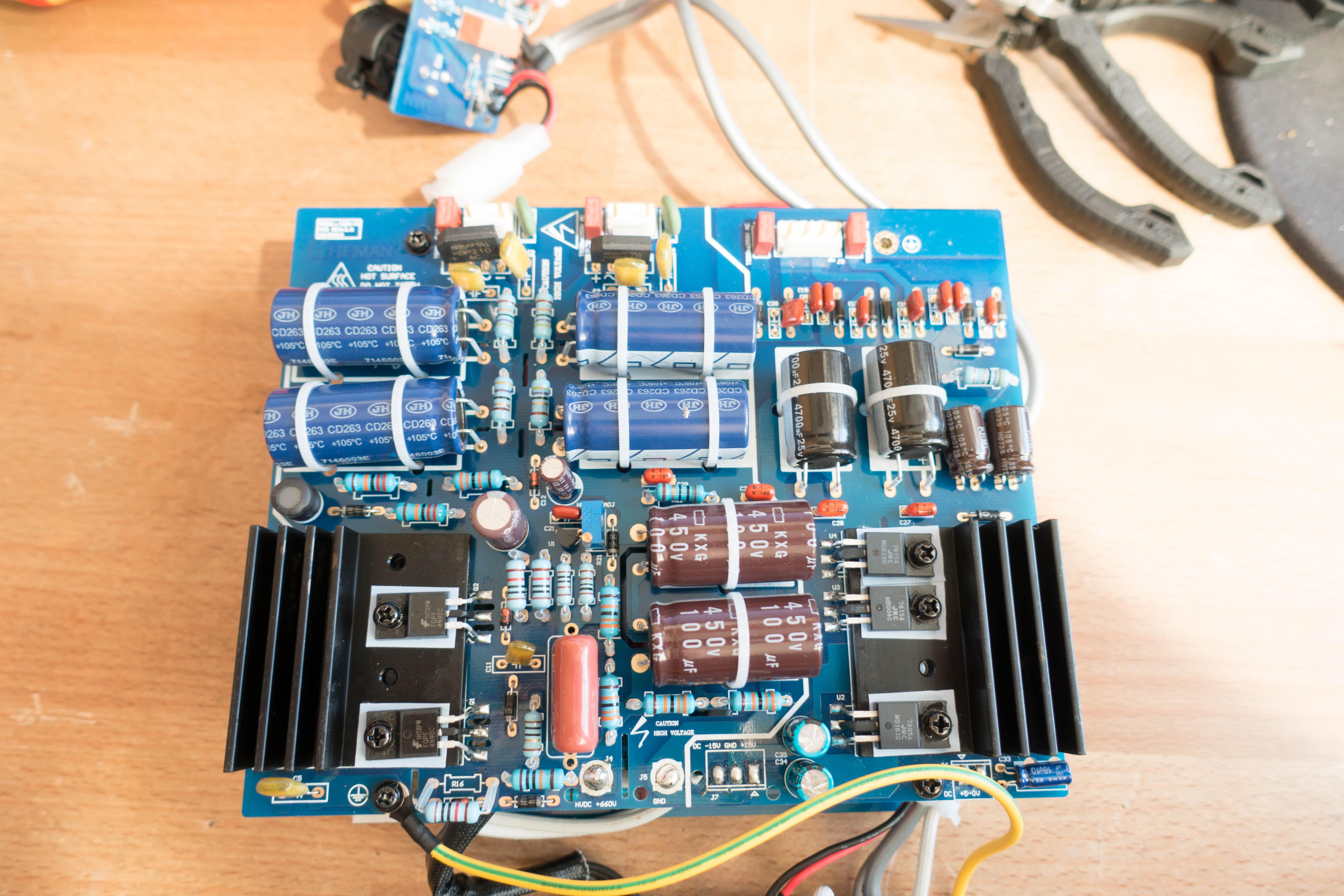
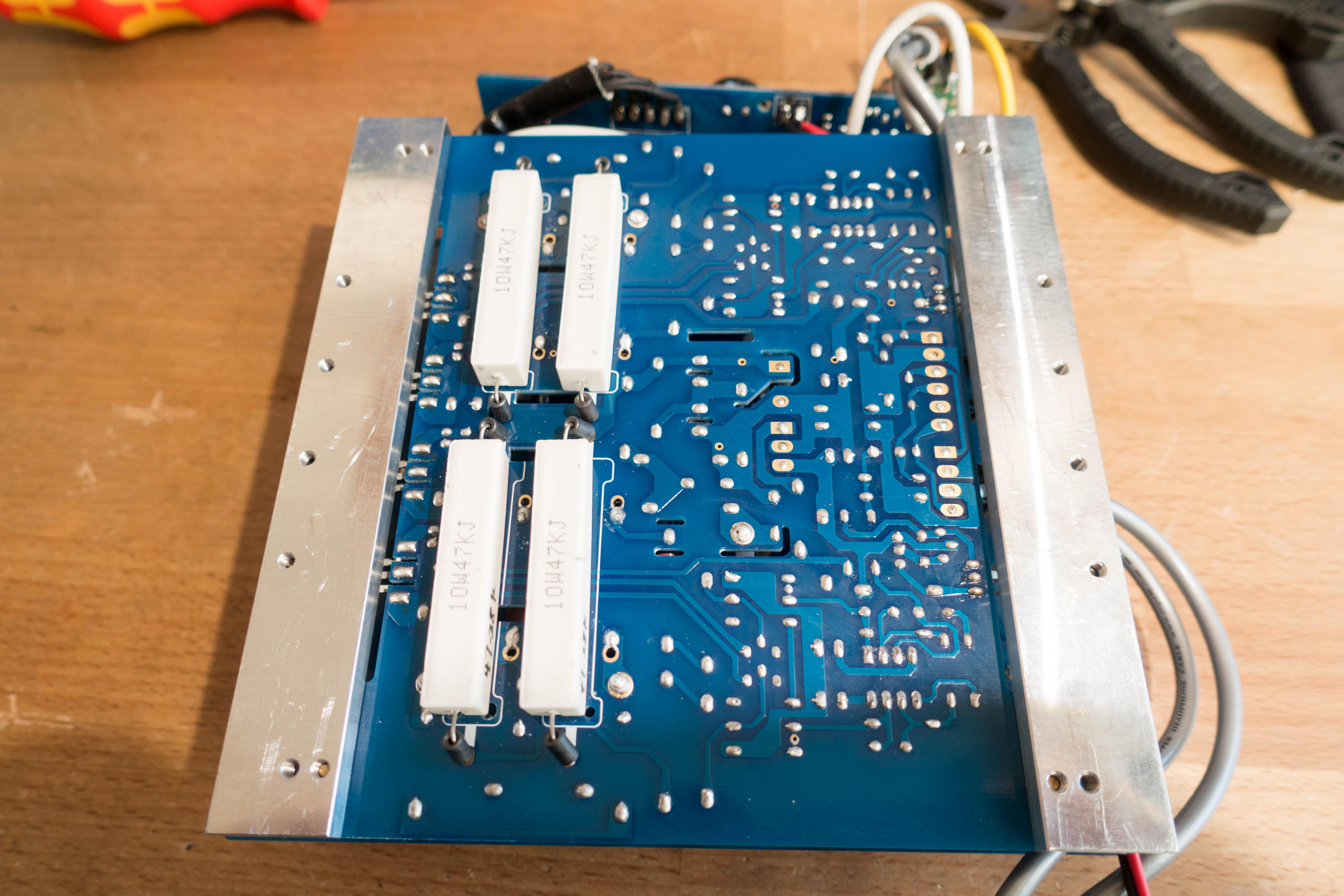
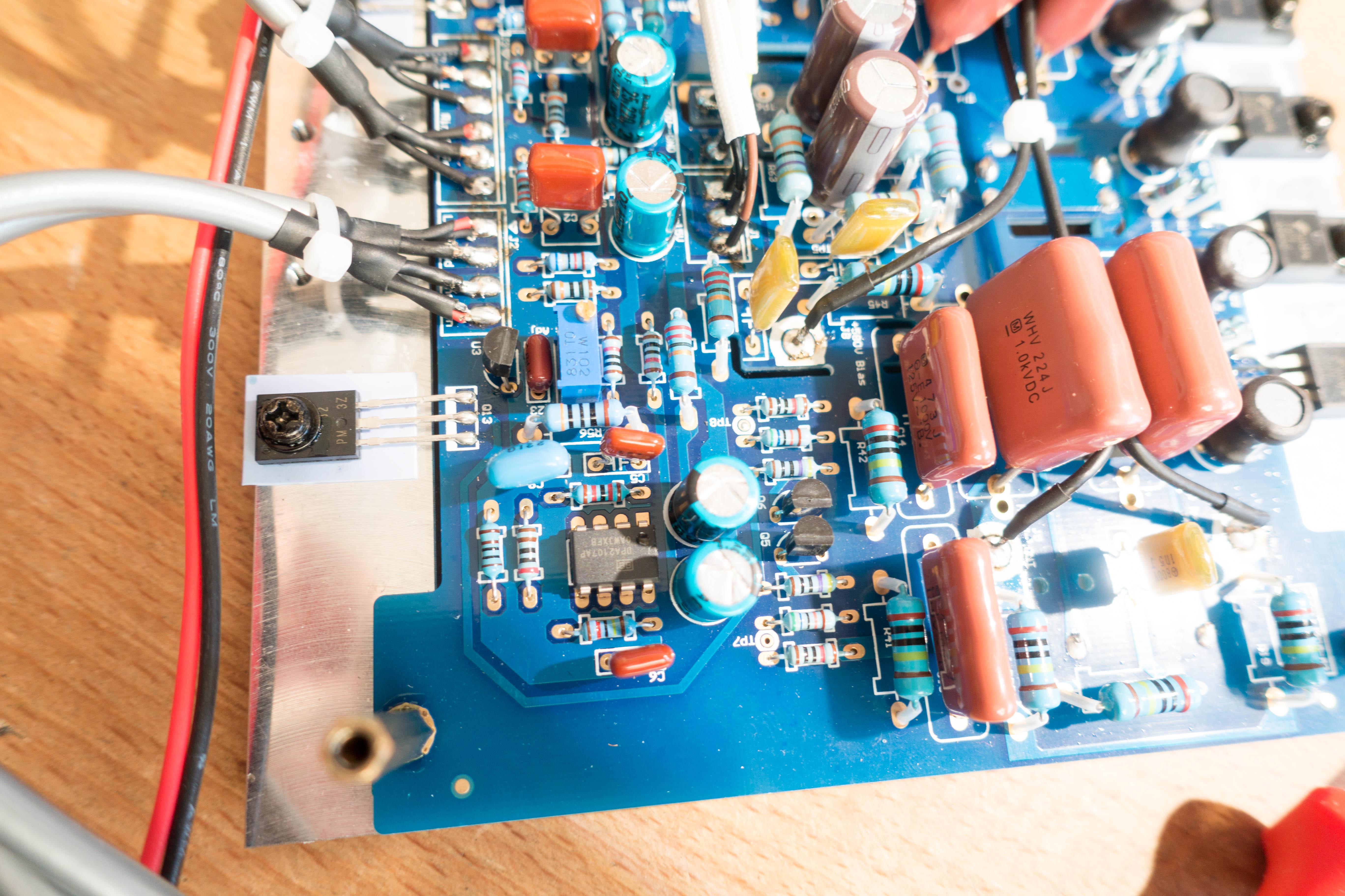
1 pointWhen I heard these were being released I just had to get a set to see if they matched the supreme crap that the original was. Now after some delays I picked the set up from the postoffice. This first post will focus mostly on the amp, the headphones will be taken apart at a later date. I have been listening to them for a few hours now so some quick impressions are in order though. Same build quality as we've come to expect from Hifiman...i.e. absolute fucking trash. First off, the phones stink badly. These are 1500$ on their own so much like the Shangri-La JR... everything is nasty synthetic crap. Same cable as the Shangri-La and Jr. use which is completely unsuitable for this role. Comfort is ok, I have the headband at max extension and the headpad is a bit uncomfortable due to that. It's odd though as they are feather light. As for the sound, well first thing you'll notice is the utter lack of usable deep bass output. I think there might be a port hiding somewhere in there as they don't squeal as they should. Tonally they are ok though, a bit thin, non offensive and the soundstage is decent. Similar league as the L300 but the bass issue has to be fixed for them to be directly compared. This is off my usual setup (Denafrips Terminator, Carbon CC) and not the included amp. Nothing from China is turned on here without being taken apart... Now for the amp, this is probably the worst chassis design ever and pretty much an utter pain to get into. Now to do so, you have to take off the front and remove the two screws which hold this PCB: Then remove the nut which holds the attenuator (more on that later) and finally remove the screws for the back panel: Undo everything there as well and the power switch and input wires are on connectors. I just cut the IEC off though as the input wires for the switch are nowhere close to safe and so is the earthing in this thing. Just look at how thin that stuff is. Also, why the hell didn't they use push on connectors for the IEC? It would make it much simpler... Once all that stuff is off you can pull out the pcb's and disconnect the transformer: Doing that I saw this gem... the bare wires from the transformer are ziptied to the input lead. Yup...no need to separate that... You can also see the earthing tag there. At this point I'm not sure where the earth is actually connected to the chassis. Two wires connect with a screw to the top PCB at the back, one from the IEC and one from the transformer shield. Granted this goes through some standoffs and to the chassis eventually but that is now how earthing should be done. On the other side of the board there is an earth wire that goes directly to the pot, which is mounted on the chassis but that is also not proper earthing. This is all very China "we don't give a fuck about safety". Now here is the top board as it comes out of the chassis: Clearly the PSU and easy to read the output voltages on the bottom. Fixed regulators for the low voltage stuff (proper JRC parts so that's nice) and simple HV supply. Now anybody familiar with old Stax amps will notice what the amp actually is at this point. Funny to see the mix of crap caps, the input caps for the LV supplies are Lelon (crap) but the output are Nichicon. Same goes for the HV side, input are "JH" (never heard of it) but the output are Nippon Chemicon. Just odd but I'll go more in depth on the PSU when I rip out all the crap caps. Here is the back of the PSU: Now the amplifier, with just three voltage rails, +/-15V and +660V there is just one possible topology here. Resistor current source feeding a single output device. So here we go: Yup this is utter shit and a clone of what Stax did with the SRA-10/12S back in 1972. It gets worse though... Say hello to the mosfet output devices and well...their typical output capacitance of 65pf. That's half the capacitance of the phones and you have two of these per driver. Yup...pure quality here. The 2SC4686A we used in the KGSSHV have a Cob of about 2.4pf and the goal here is to keep it as low as possible otherwise it will mess up the sound signature of the amp. Think Cavalli Liquid Lightning here... Here is the input section and the we need to discuss that a bit. So this amp has a balanced input but it isn't balanced. The volume control is one of those cheapo 21 step steppers you can find on ebay for 15$ and just two decks. There are also just two wires coming from the input board per channel, Rin and ground... Funny too is that the instructions manual specifically states that the volume control is a 21 step relay based attenuator. Yeah...that is a fucking lie. So the amp is resistor loaded mosfet with output capacitance matching the load and isn't actually balanced. The output caps are at least larger what what Stax used back in the day so that is something... Now we need to discuss this board: This is on front panel and for some reason the outputs have relays on them and 1K output resistors. While better than nothing, something in the 5K range would be a better choice. Now comes the point some were waiting for, can this thing be used with Stax sets? At this point I'd say no, there are just 2M ballast resistors on that board for each output (no idea why they used two) so this amp can damage Stax. Ohhh and one funny thing before I go do something productive...they hand matched the output load resistors... Finally just a dump of the extra pics I took if anybody wants to look through them.


 1 point
 -
1 point1 point1 point1 pointThin and a bit lifeless with reasonably good soundstage. Not bad but not great either and it really depends on what you are listening to. On some music it is unbearably thin while on some it works just fine. The cable is the biggest issue one these though, it's too short and just unsafe garbage. I'm also detecting some noise in the left earpiece so squealing might be an issue with these. Some notes on the amp, the XLR input is completely fake and the - leg of the input just goes through a 630 ohm resistor to ground. Pure class there... The soldering on this thing is world class in the wrong direction, a lot of parts are loose when I try to move them so I wonder if this thing passed through quality control at all. I never turned it on so I can't know if it ever worked. I will go through it and make something usable from this mess though... I was looking up the caps I had never come across and yup, they will be out of there. I'm also going to redo the input section completely as the stepped attenuator feels like garbage. Some 10M90's instead of the load resistors too... we'll see what I can fit in there.1 pointNothing like the classical music before a hard bicycle race...1 pointTest Tone @ Home live right now: http://mixlr.com/illuminator/chat1 point1 pointHalf the fun is to take this stuff apart but the sheer lack of quality here is astounding. So the large blue caps in the PSU, I wanted to check out the bottom to see if they had any further markings and cut off the zip ties and bent it upwards. Well...one of the legs just popped off which shows the soldering quality here. It was barely hanging on as they clearly trimmed the legs before soldering and nobody spent enough time on each joint for the solder to flow through to the other side of the holes. So I guess as full rebuild of the PSU is on order...on the brand new 1100$ amp.1 point1 pointFinally got around to finalize my Megatron, fitted into one chassis with GRHV.1 point0 points


Important Information
By using this site, you agree to our Terms of Use.