

Leaderboard

Popular Content
Showing content with the highest reputation on 02/27/19 in Posts
-
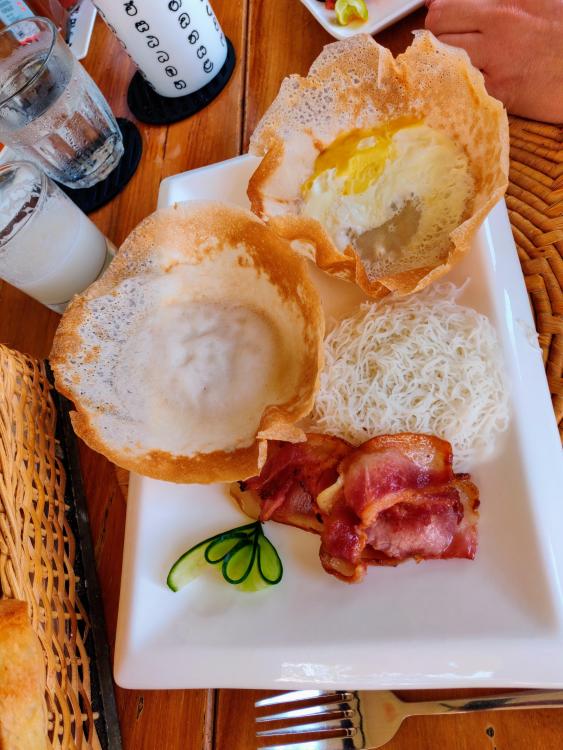
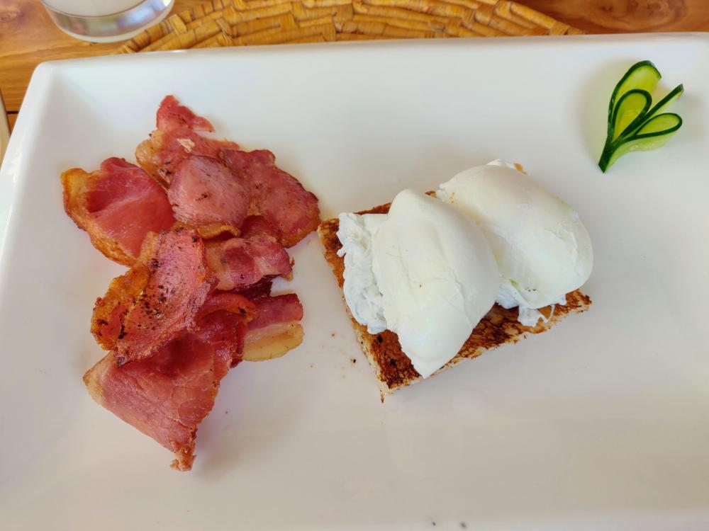
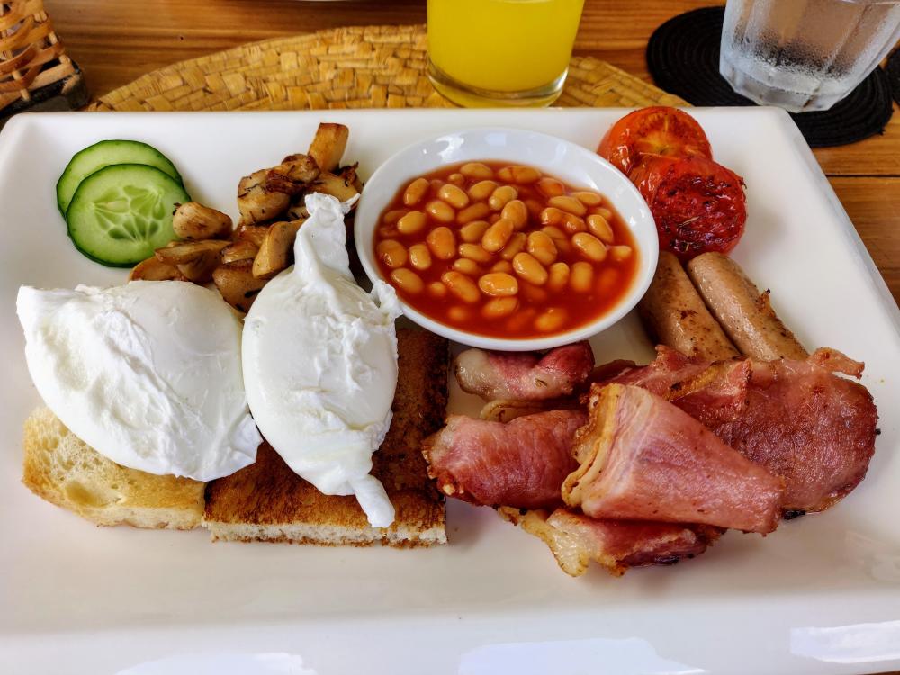
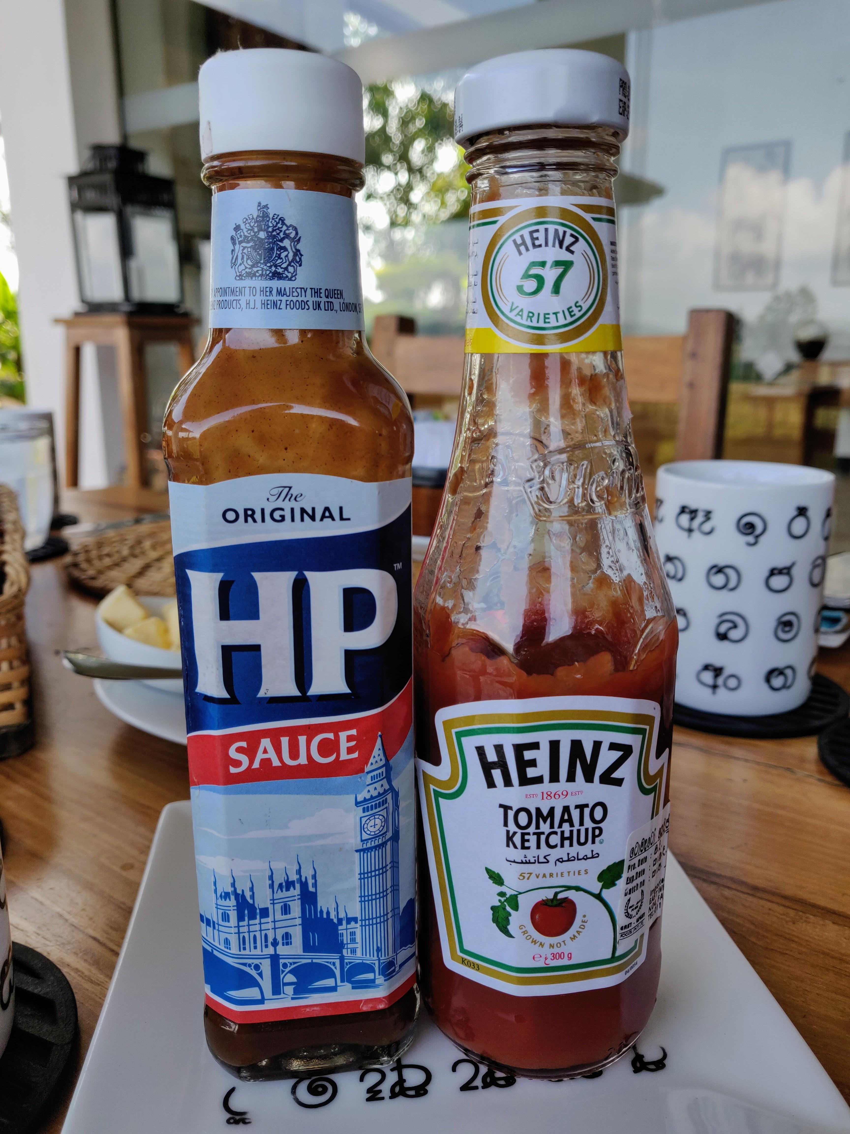
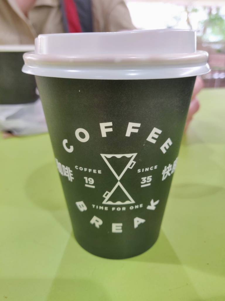
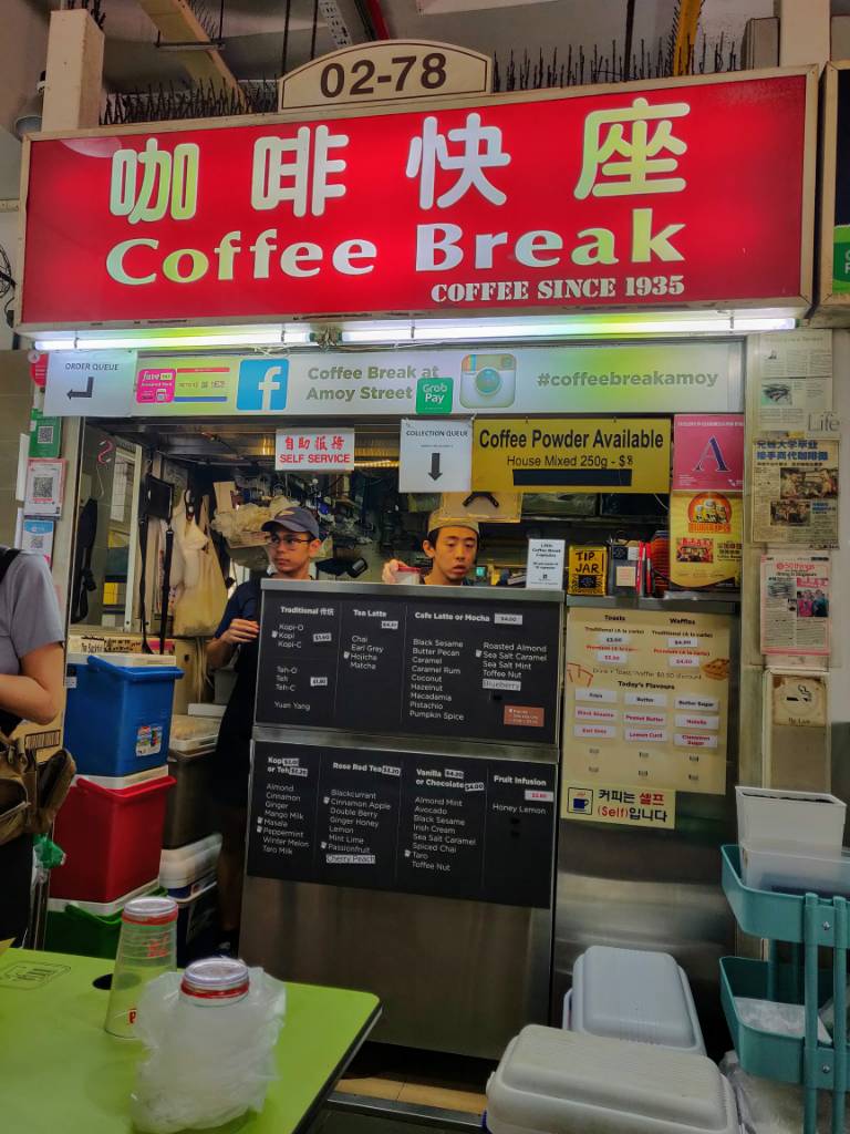
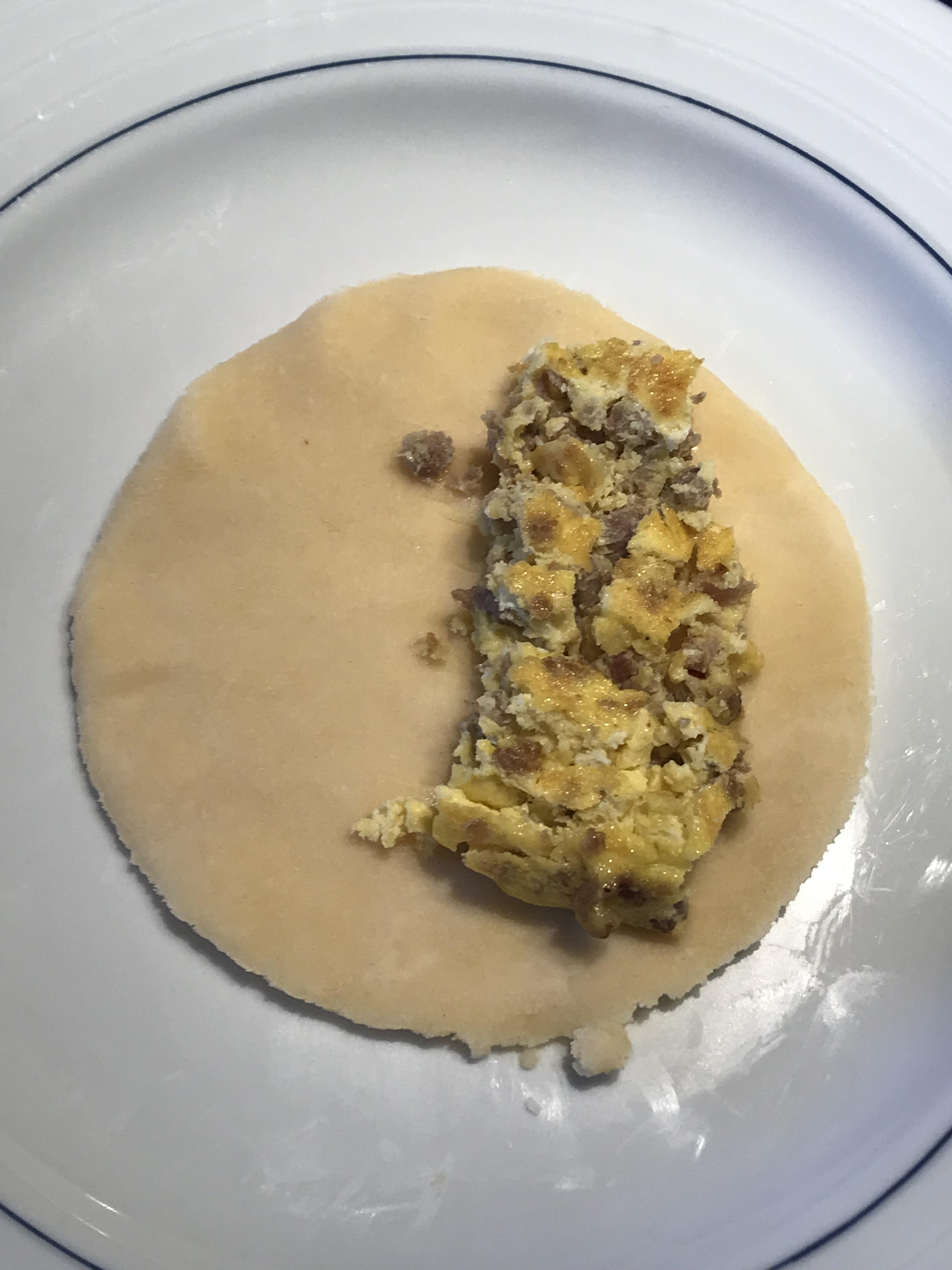
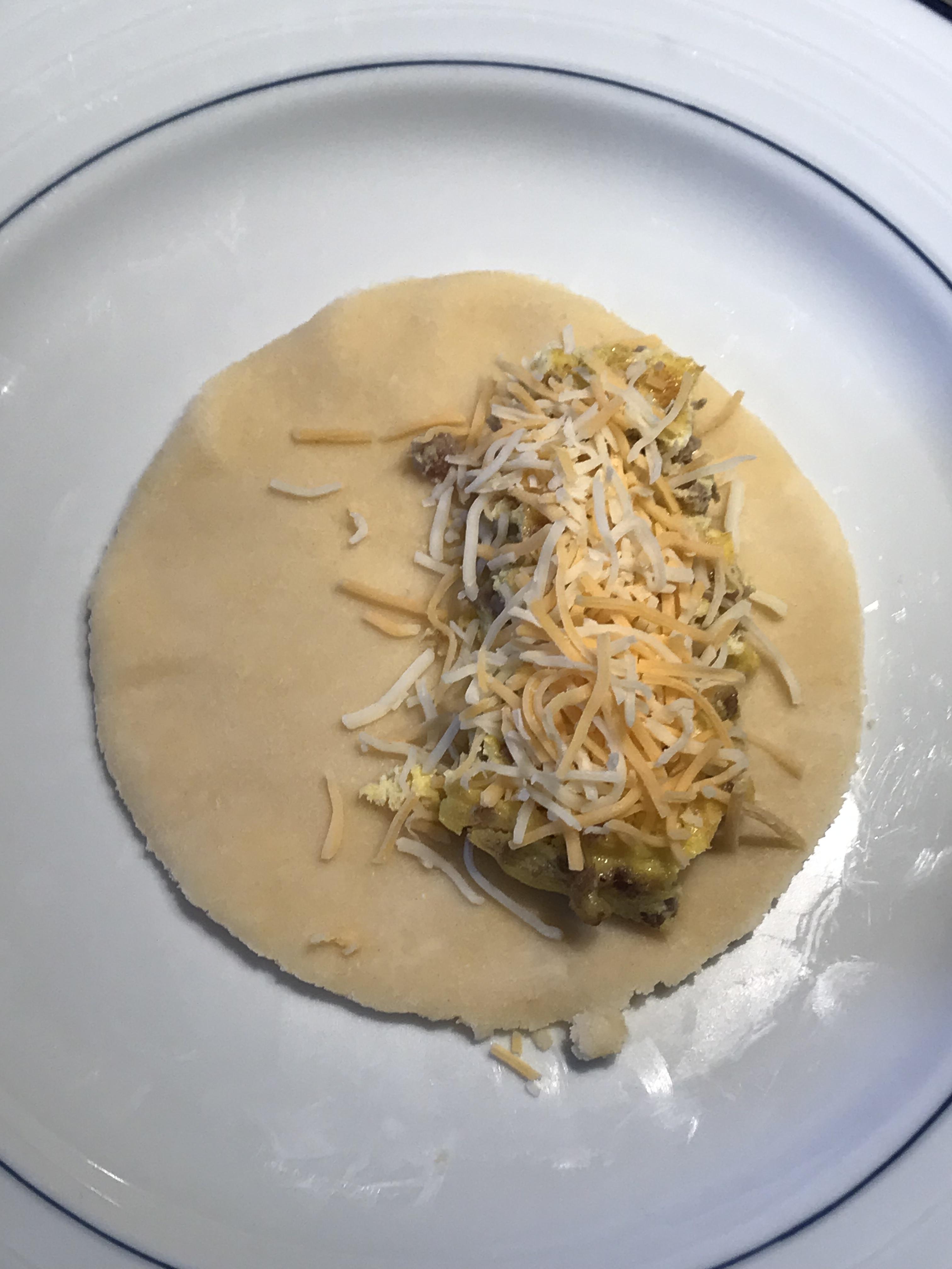
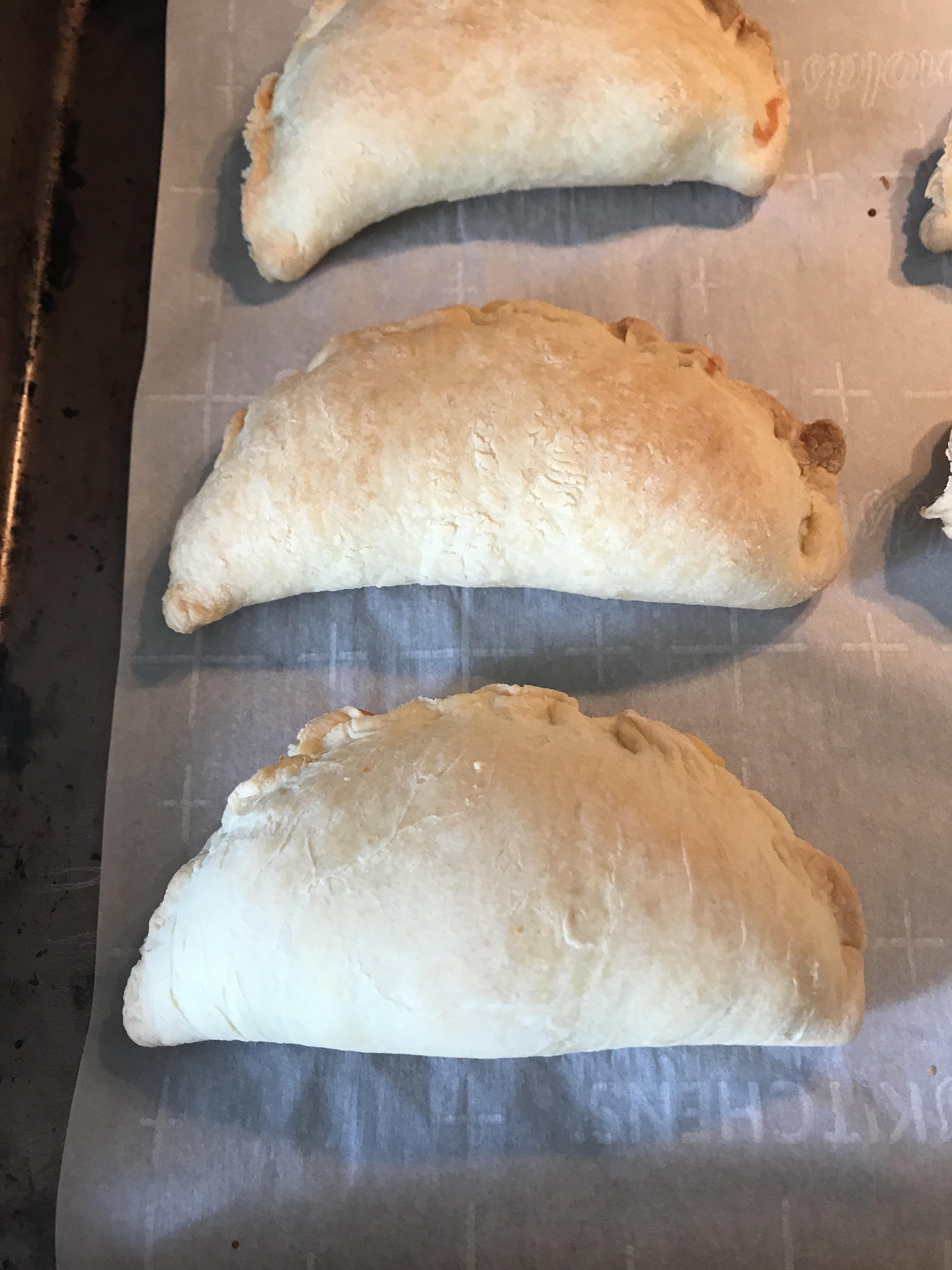
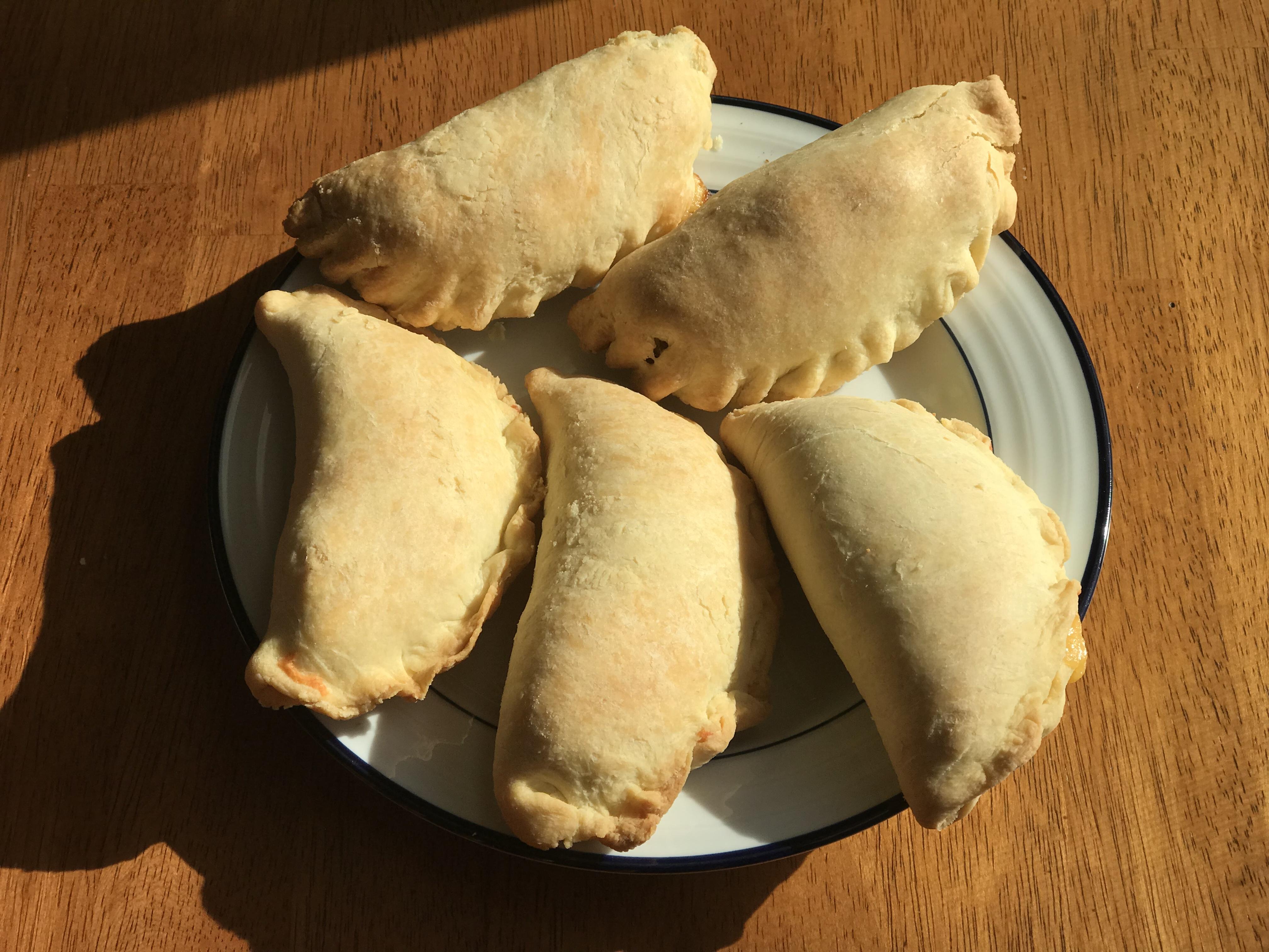
4 pointsMore health More fun More local (& extra fun) More views Local spices Can you tell this place is run by a Brit?


 4 points
 -
2 pointsI am new to this thread, but wanted to comment that this is one of the nicest builds I have ever seen. It looks like a boutique Japanese high end amp, and thats a compliment. I hope that I can come close on the build I am contemplating.2 points
-
2 points
-
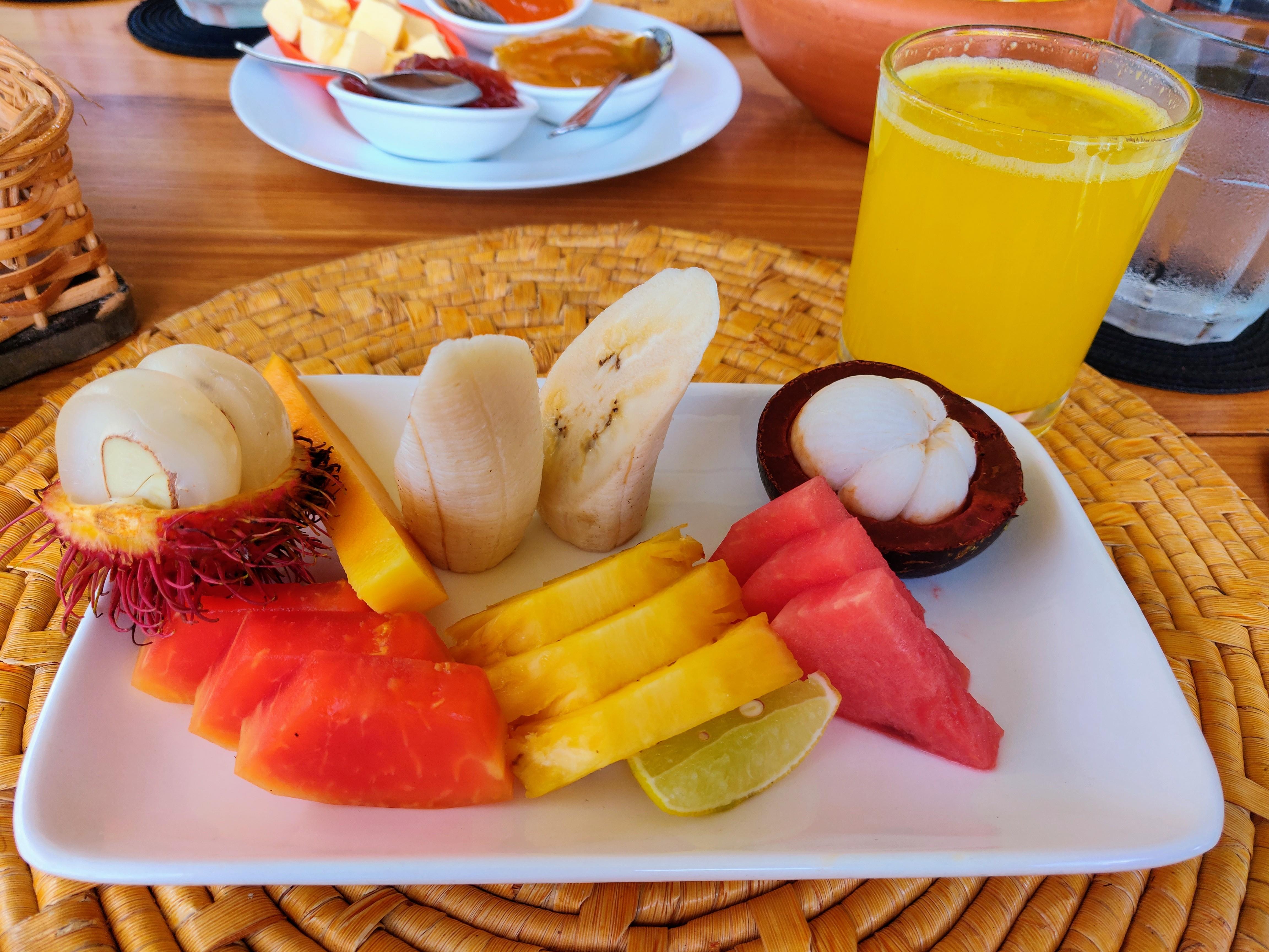
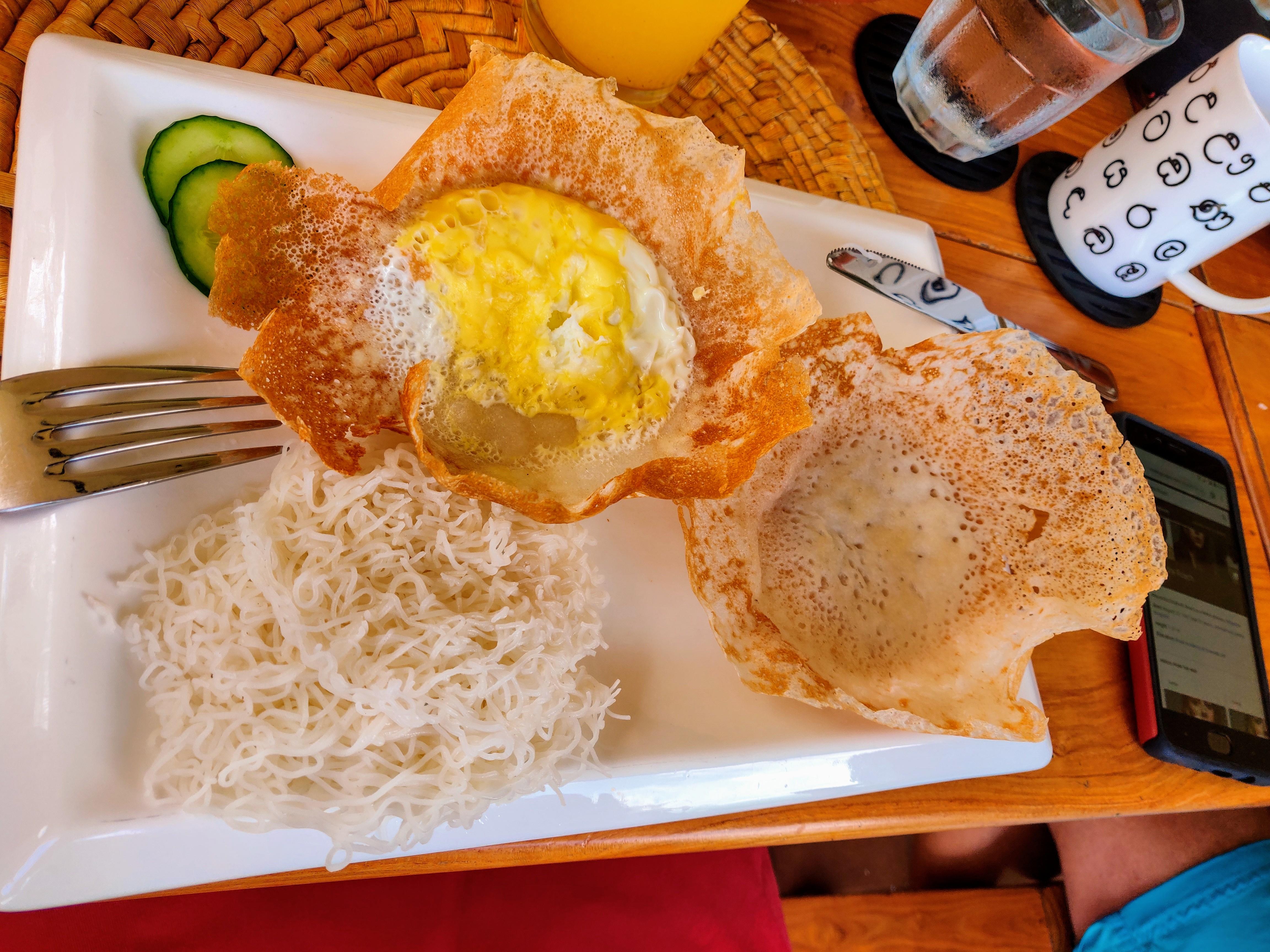
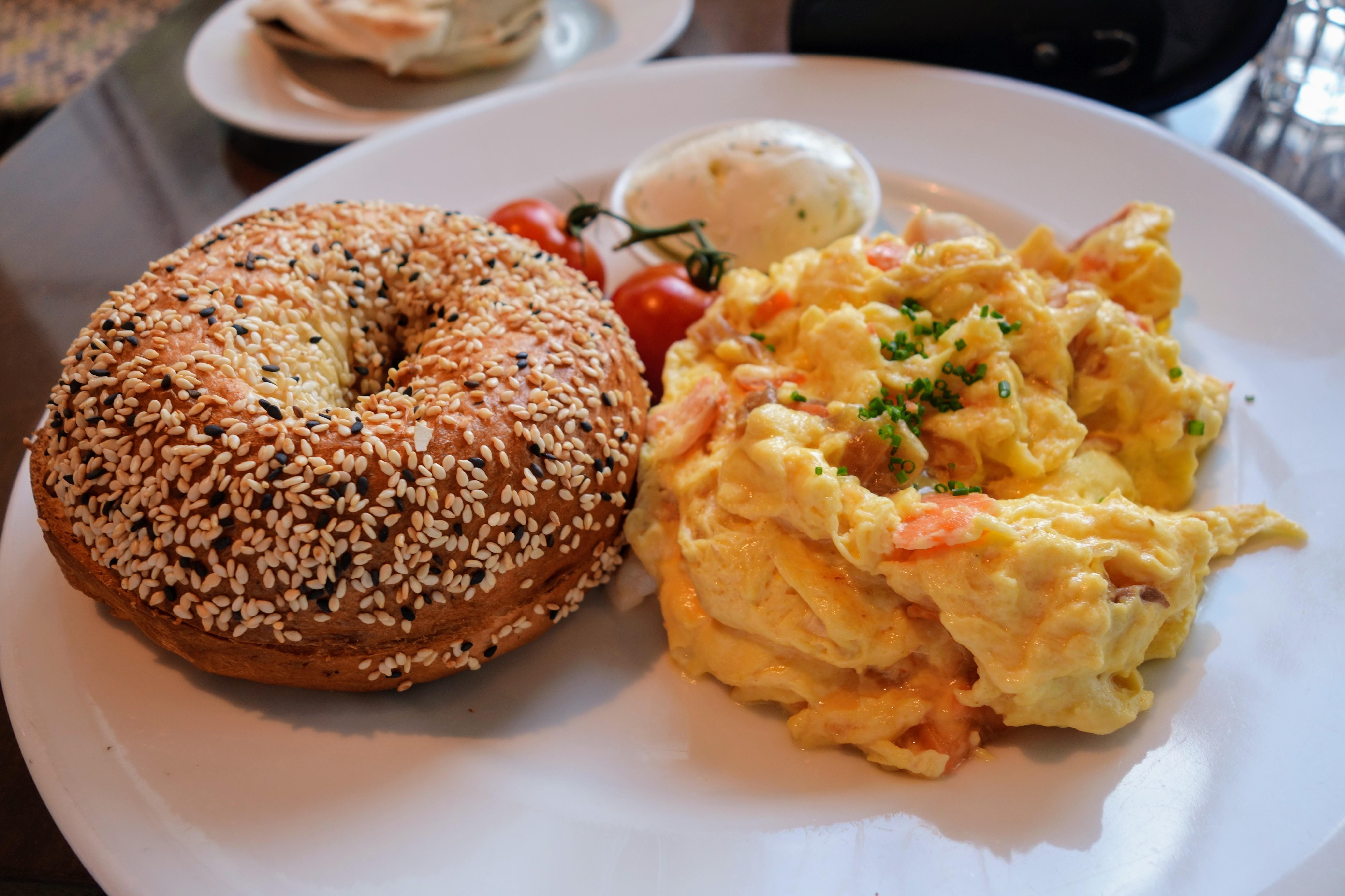
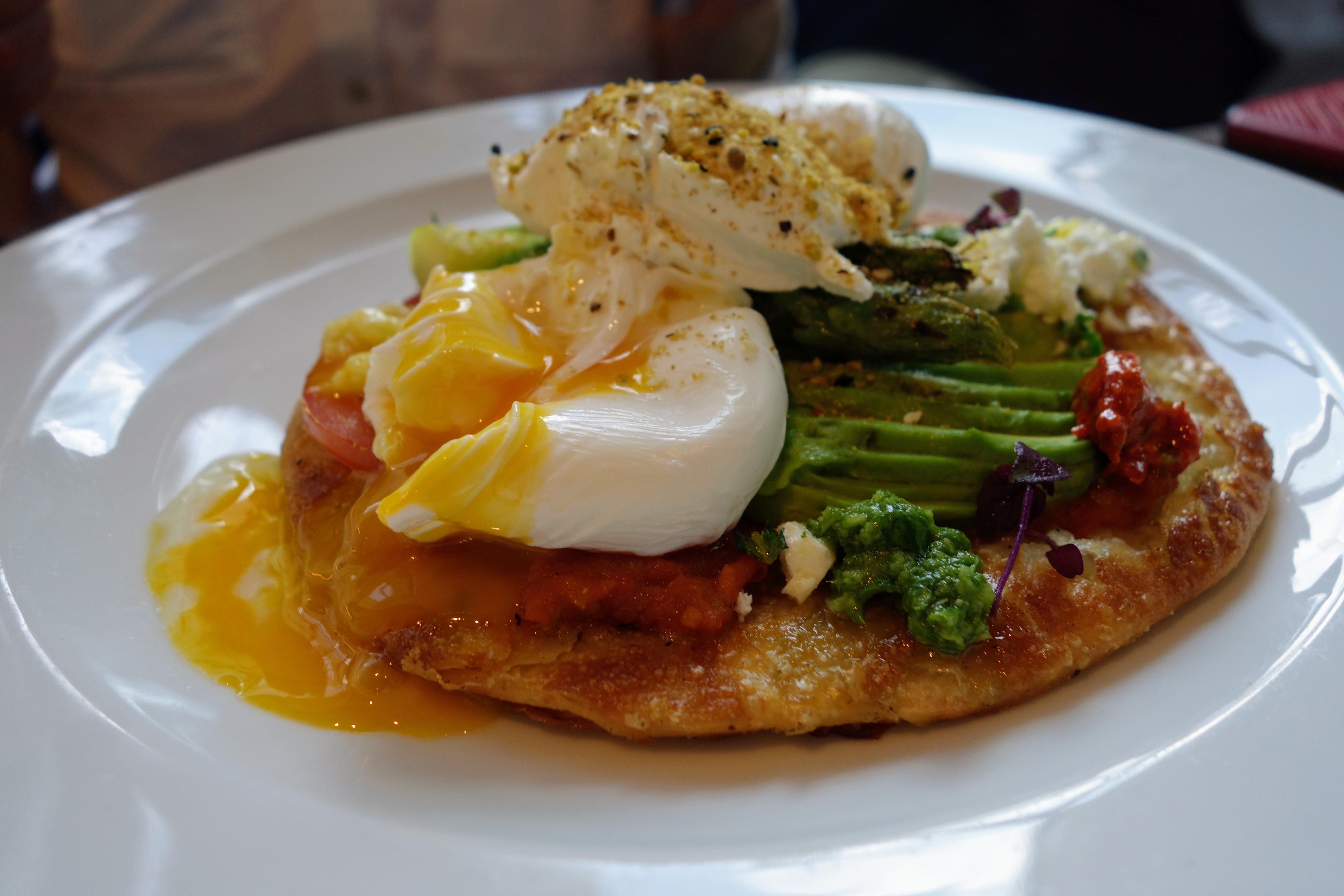
2 pointsBreakfast. Healthy part Fun Part Local Part (Joanne) Location / View / lighting conditions part


 2 points
 -
2 points
-
1 point
-
Stumbled across this. Be sure and stick around for Linda Ronstadt's bit.1 point
-
1 point
-
1 pointI have switched to this: Sunny Health & Fitness Asuna 5100 Magnetic Belt Drive Commercial Indoor Cycling Bike Silver https://smile.amazon.com/dp/B0172EEHXC/ref=cm_sw_r_cp_apa_i_VGFDCbXFQMFMP Plus pedal power meters to do Peloton and Zwift. We absolutely love it. Let's us move back and forth between my wife and I in about a minute but still rides great. Super quiet. Zwift username?1 point
-
1 point
-
1 point1 pointI use a Wahoo powered trainer and Zwift, which a lot of HCers also use, as my much more useful spin bike. I obviously need to be using it a lot more than I am, which anyone on Zwift can tell you.1 point1 pointNibbles to go with Sri Lankan afternoon high tea Think Sugar, five ways.
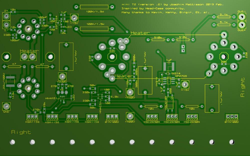
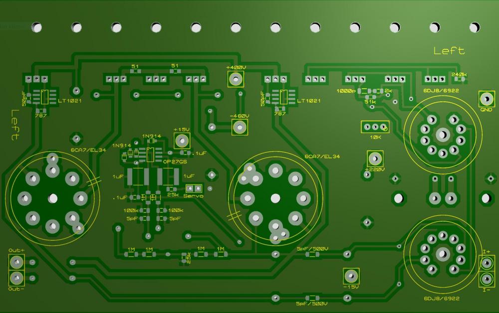
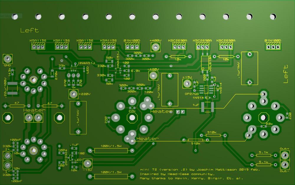
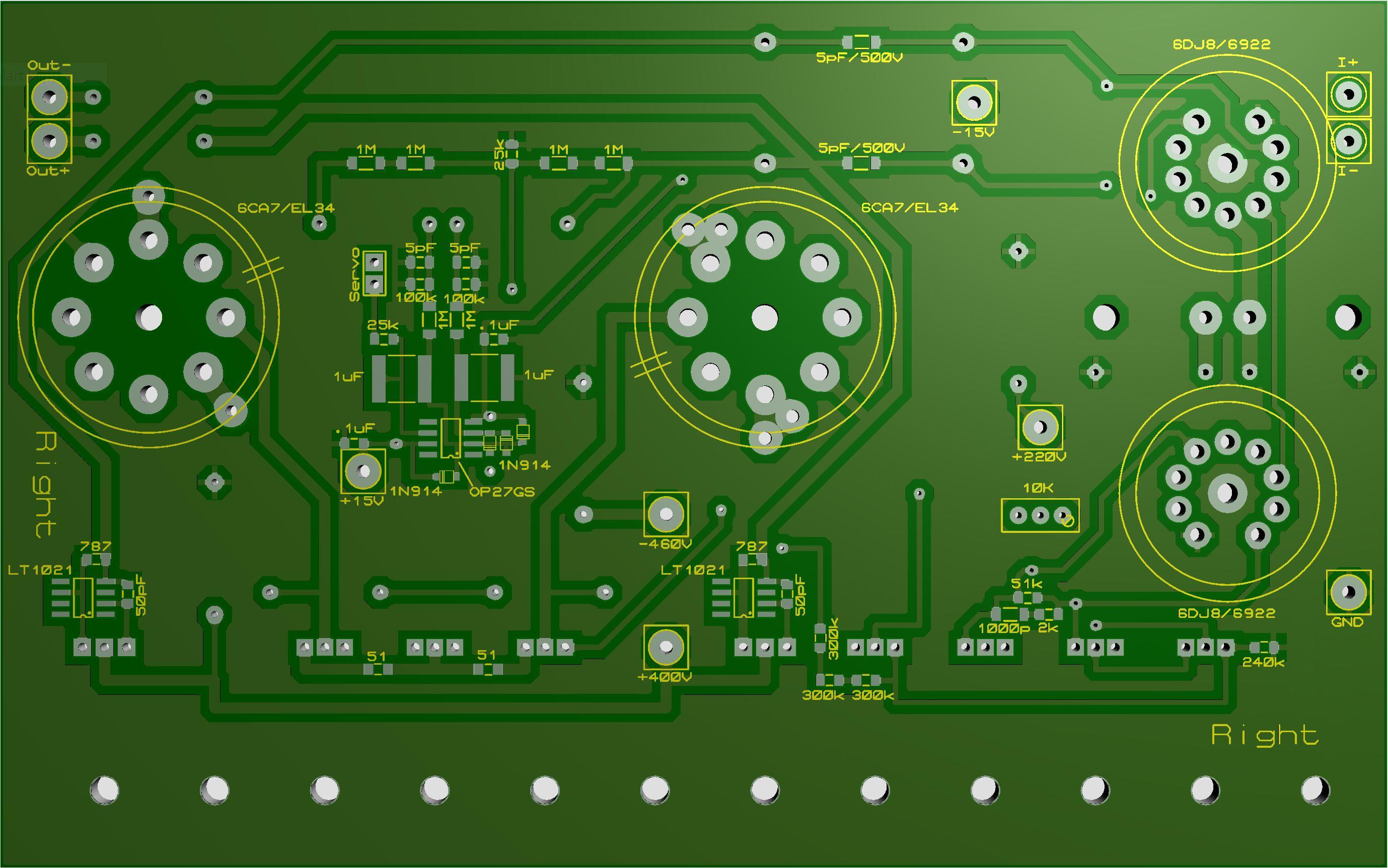
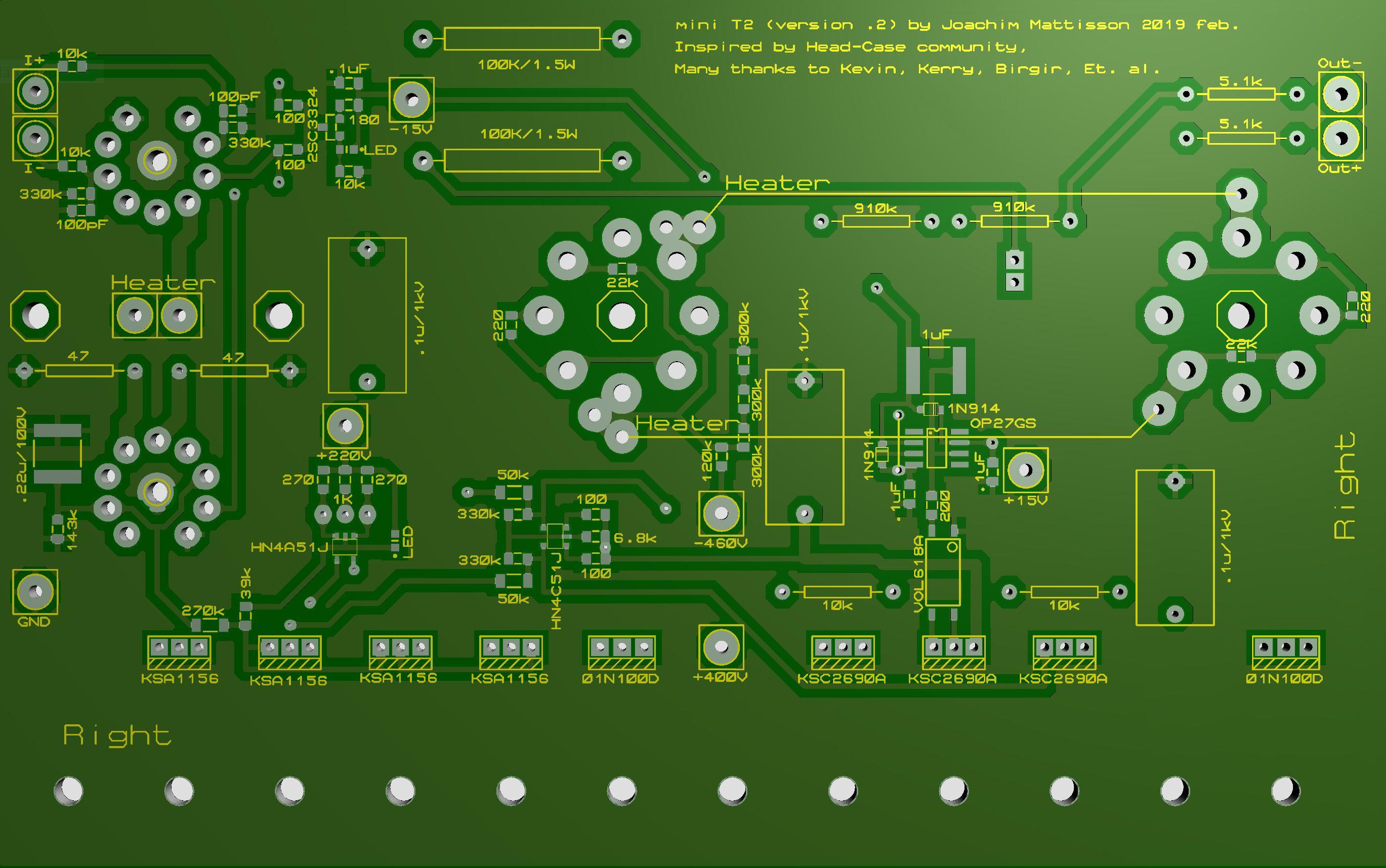
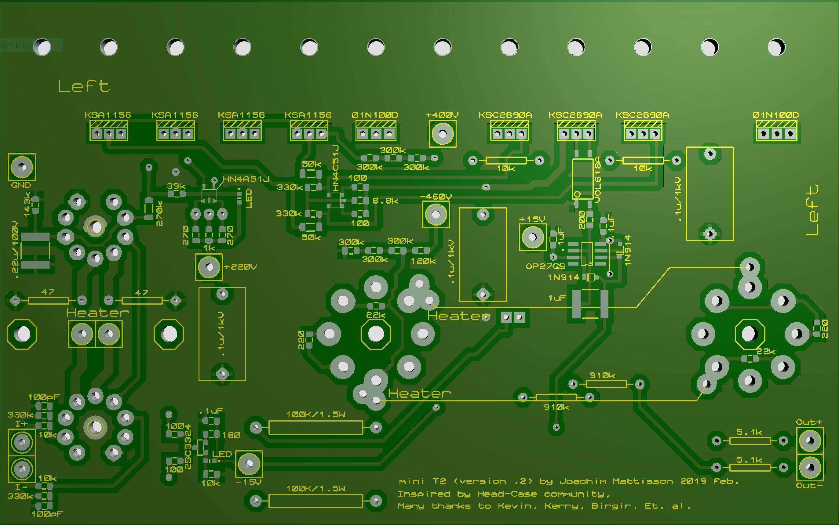
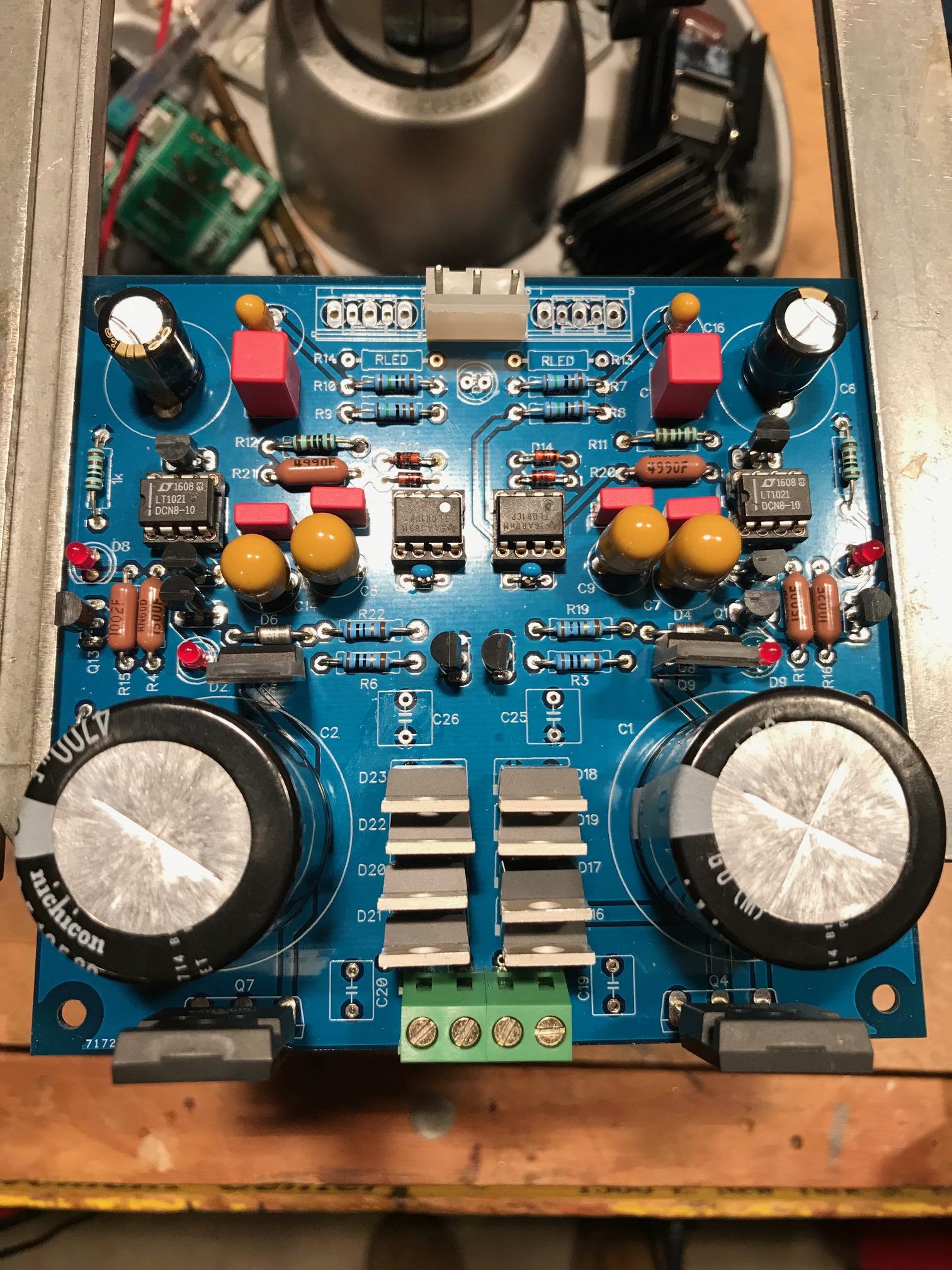
 1 point1 pointA few points regarding the boards Michael have had made on my gerbers. They are basically the same as my kitchen made boards I made five months ago. The small tube footprint has no hole for the center pin. So far I’ve cut away the center pin on the small tube socket after checking the pin holders to be not to tight nor to loose. One time I got tube sockets where the tubes fell out when turning upside down. So either you have to cut pin or drill a hole. Be aware that upper tube has a trace between the grids that might be to close to center pin. Right board 270K resistor has a 0805 pad (intention was 1206). It’s possible to solder a 1206 resistor on the 0805 pad. If +220V you get about 130 V cross the resistor so Vishay CRCW0805 is OK here. But with +250 V you get close to CRCW0805’s limit of 150 V. Some of component values on silk screen are poorly place and almost unreadable. The blame is entirely on me, I’m very sorry. There are four octagons on bottom side. One at each big tube socket center hole and one each side of small tubes filaments connections. Here I have standoffs. A few comments on updated layouts. Small tube footprint with center hole. 270K resistor pad corrected - now 1206. Silk screen remade. Pleas notify me if there is any left that needs additional attention. Now “value” of connections on both sides (except heaters). No terminal blocks on my boards. Top right. Updated 2019-02-27. Bottom right. Updated 2019-02-27. Top left . Updated 2019-02-27. Bottom left. Updated 2019-02-27. I call above version .2. My kitchen made and Michaels are version .1. Regarding this amplifier - there is nothing I've invented. I just have picked up different things and tried to put them together. As: Opto servo (the only offset servo you need) by Kevin. 01N100D/TL1021 current source by Kerry. Schematic of Stax T2 provided by Kevin, Et. al. Schematic of Stax T8000 provided by Kevin and Birgir. Etc. etc. Thanks for all knowledge, information and inspiration from you DIYers and Head-Case members. Please look for errors or other issues.
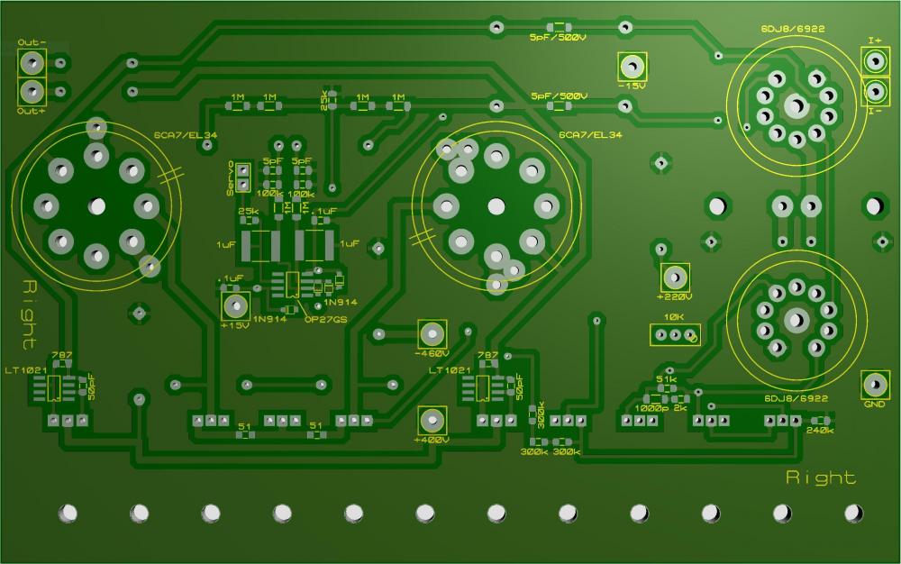
 1 pointHere's a pic of the 35mm multioutput boards I had run. DImensions are 116 x 107mm, with the mounting holes on 106 x 97mm centers. On Semi schottky rectifiers, 30mm caps installed. I'm working on shrinking this down to match the size and mounting pattern of Kevin's boards (110 x 93 with mtg. holes 100 x 83), and so far it looks good, though I'll probably have to lose the following: power LED and resistors the current board allows 220uf caps that are 18mm diam. with 7.5mm lead spacing in the upper corners. Not sure what cap was the target here, as a Silmic is 12.5mm d x 5mm ls (for 35V). This will shrink to Silmic size (though I don't use them). This doesn't have the rail balance pot and stuff on it (to equalize the +/- rails). I'll take a look at that and see if it would fit. I'll probably ditch the 1uf film caps following the main filter caps. Not sure they are really of any benefit. These boards do support R-C snubbers. You could also do Mark Johnson's (diyaudio-Quasimodo thread) favored R-C-R snubber by soldering the 0.01uf film caps across the 2 AC inputs on the bottom. I may try to accommodate these on the board itself.
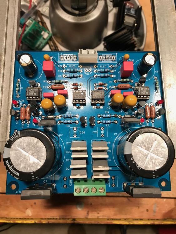 1 point1 pointAfter two days of voir dire they seated a jury and I am not on it! Yaaaaaas! Jury duty... really interesting and fun to do once, after that, pass!1 pointScooped up this original “thriller” in excellent condition from an old record store
 1 point1 pointhttps://wildhoney.com.sg/menus/i-love-ny/ https://wildhoney.com.sg/menus/flinders-lane/

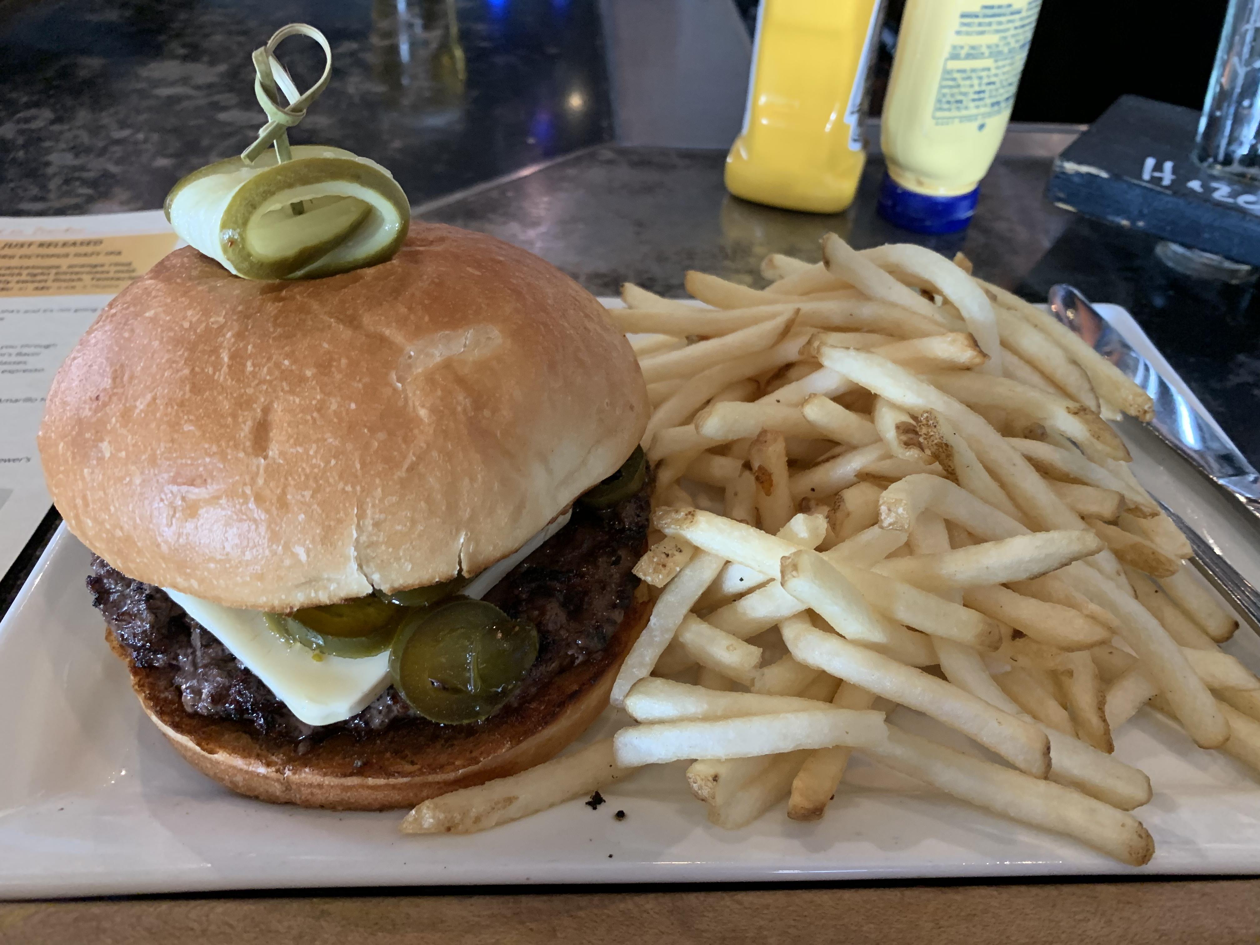
 1 point1 point1 pointBurger at Fifty Fifty Brewing: half pound beef with jalapeños and honey cream cheese. Sweet, spicy, delicious, to use the Mikey three word tasting notes style.
 1 point1 point1 point1 pointHave you tried to put the strap into the retainer before closing the clasp? That's how I do it on my Zenith which had a similar issue.1 point


Important Information
By using this site, you agree to our Terms of Use.