Leaderboard


Popular Content
Showing content with the highest reputation on 02/21/2021 in all areas
-
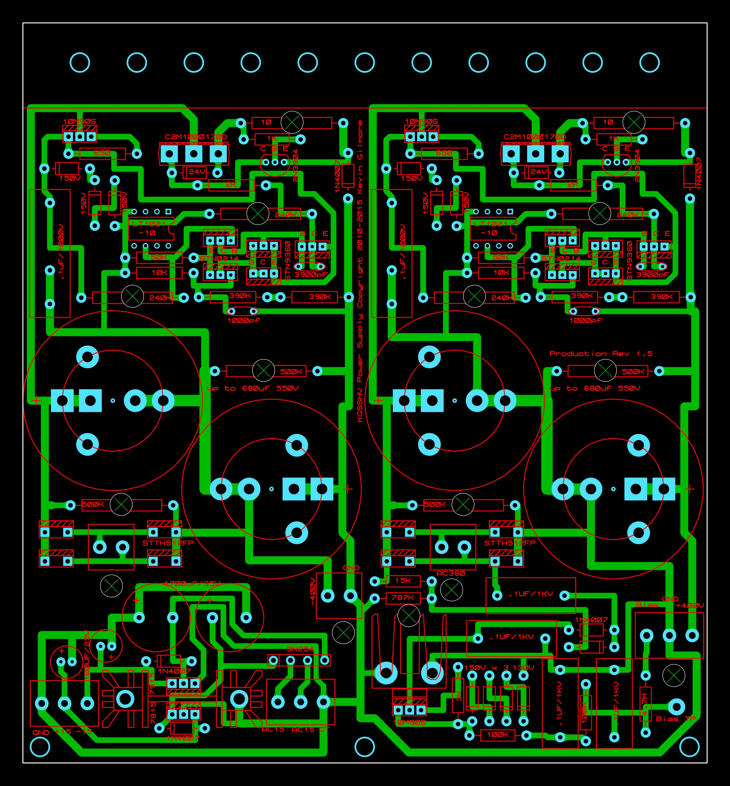
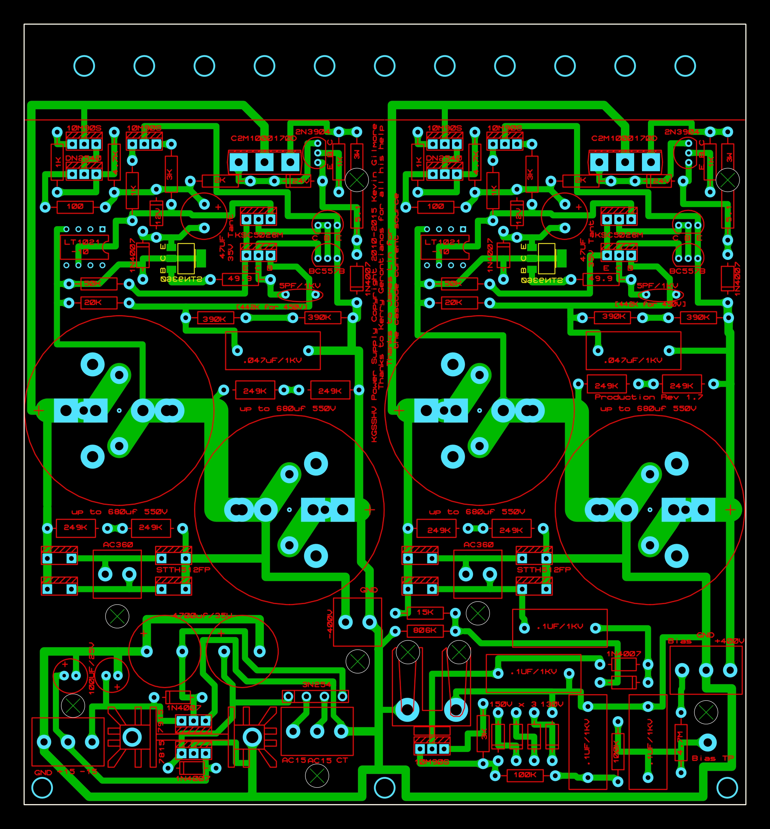
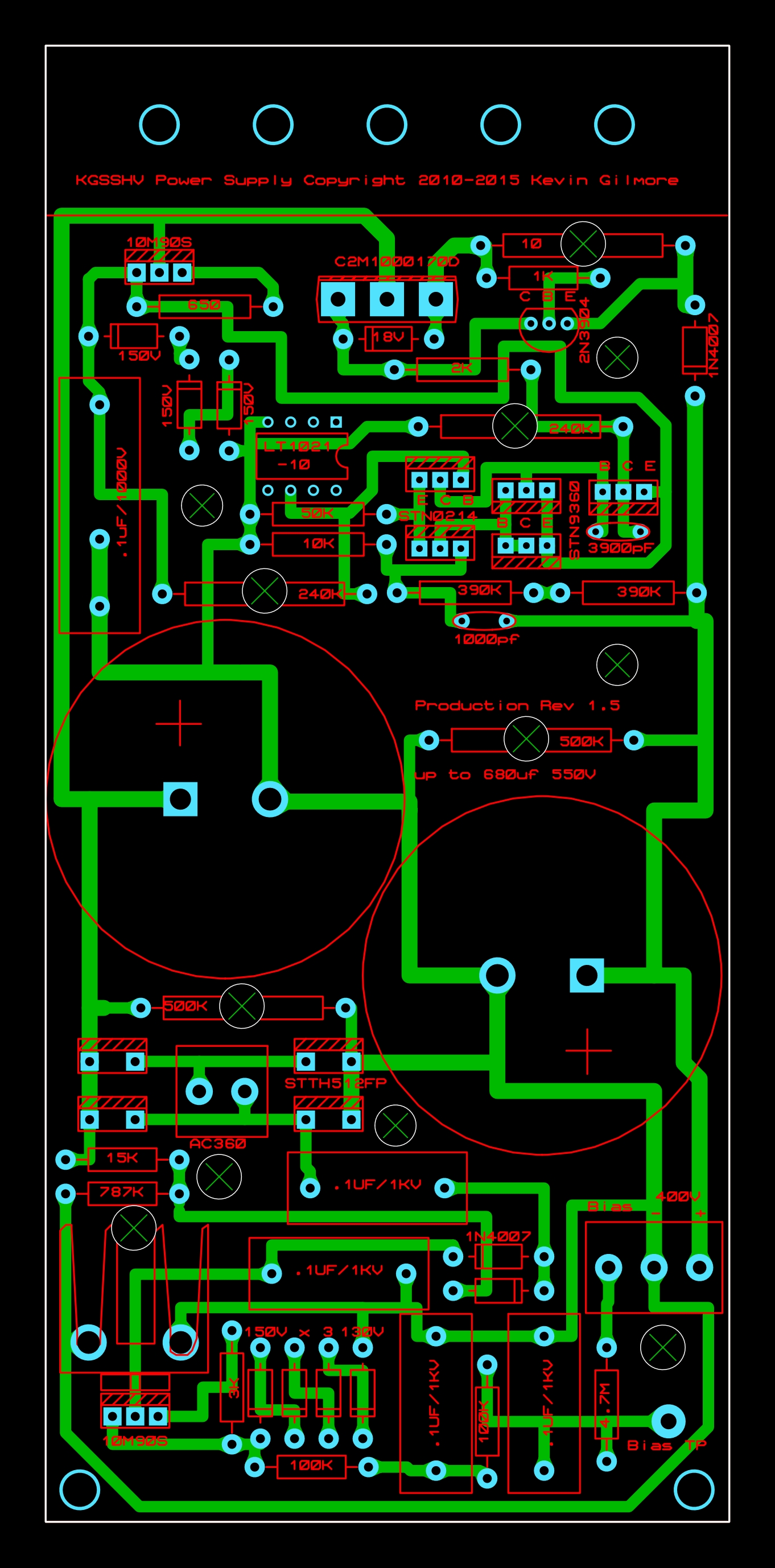
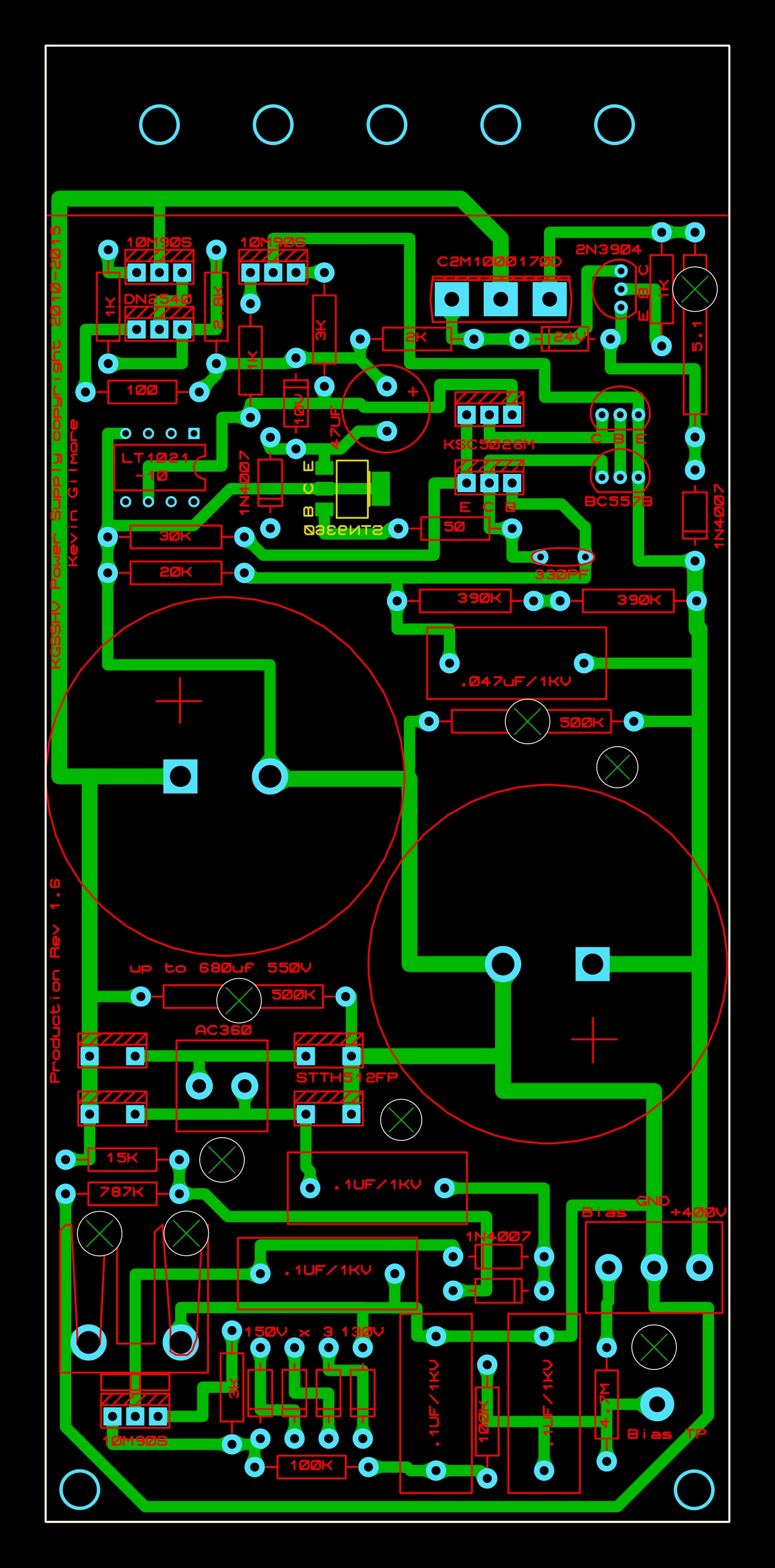
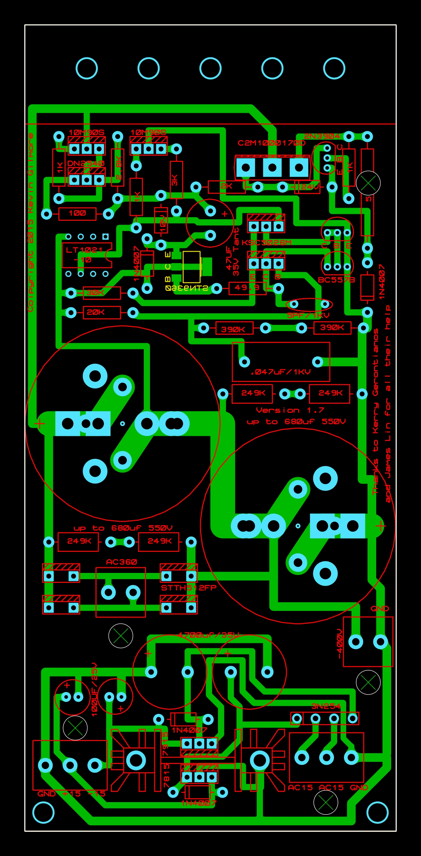
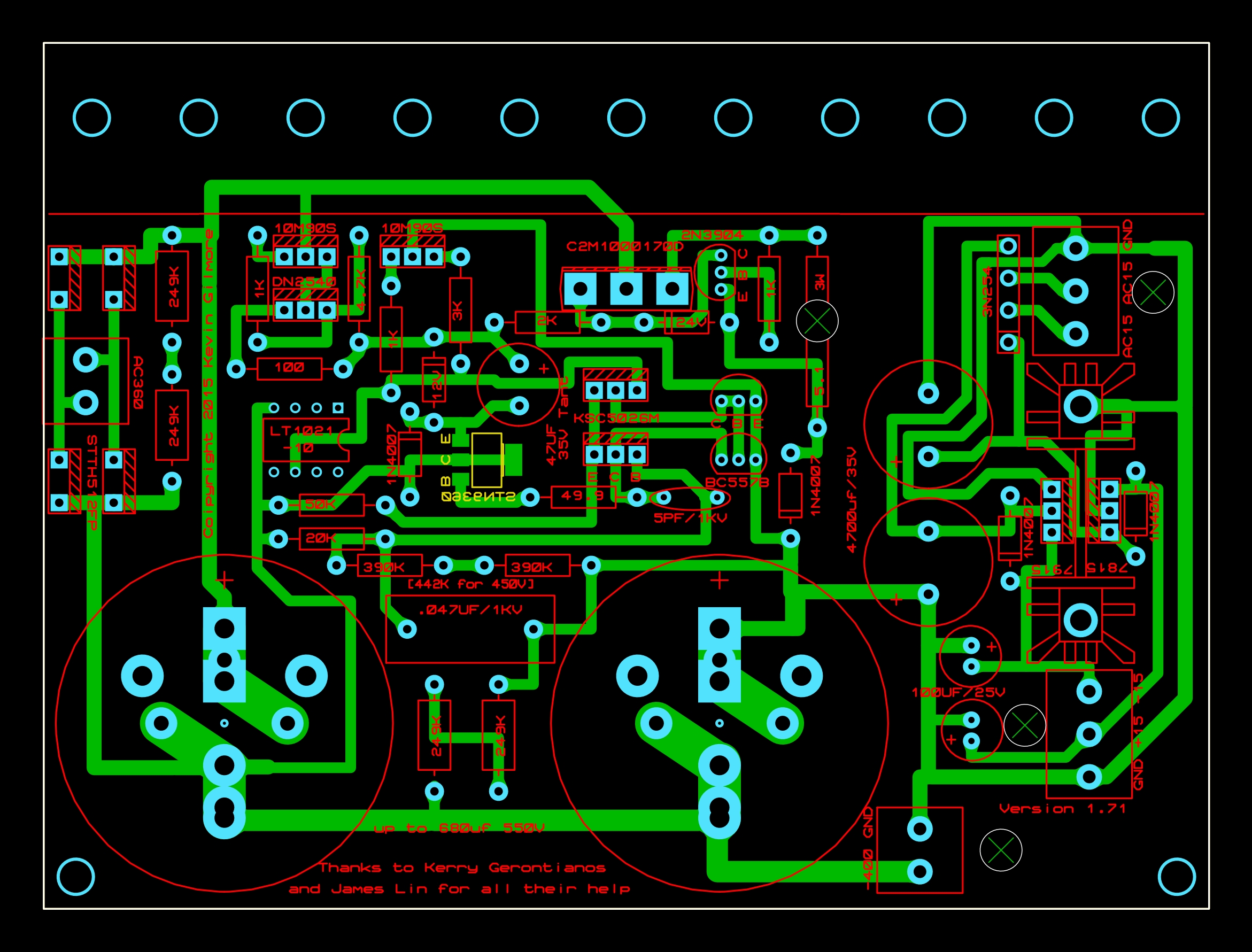
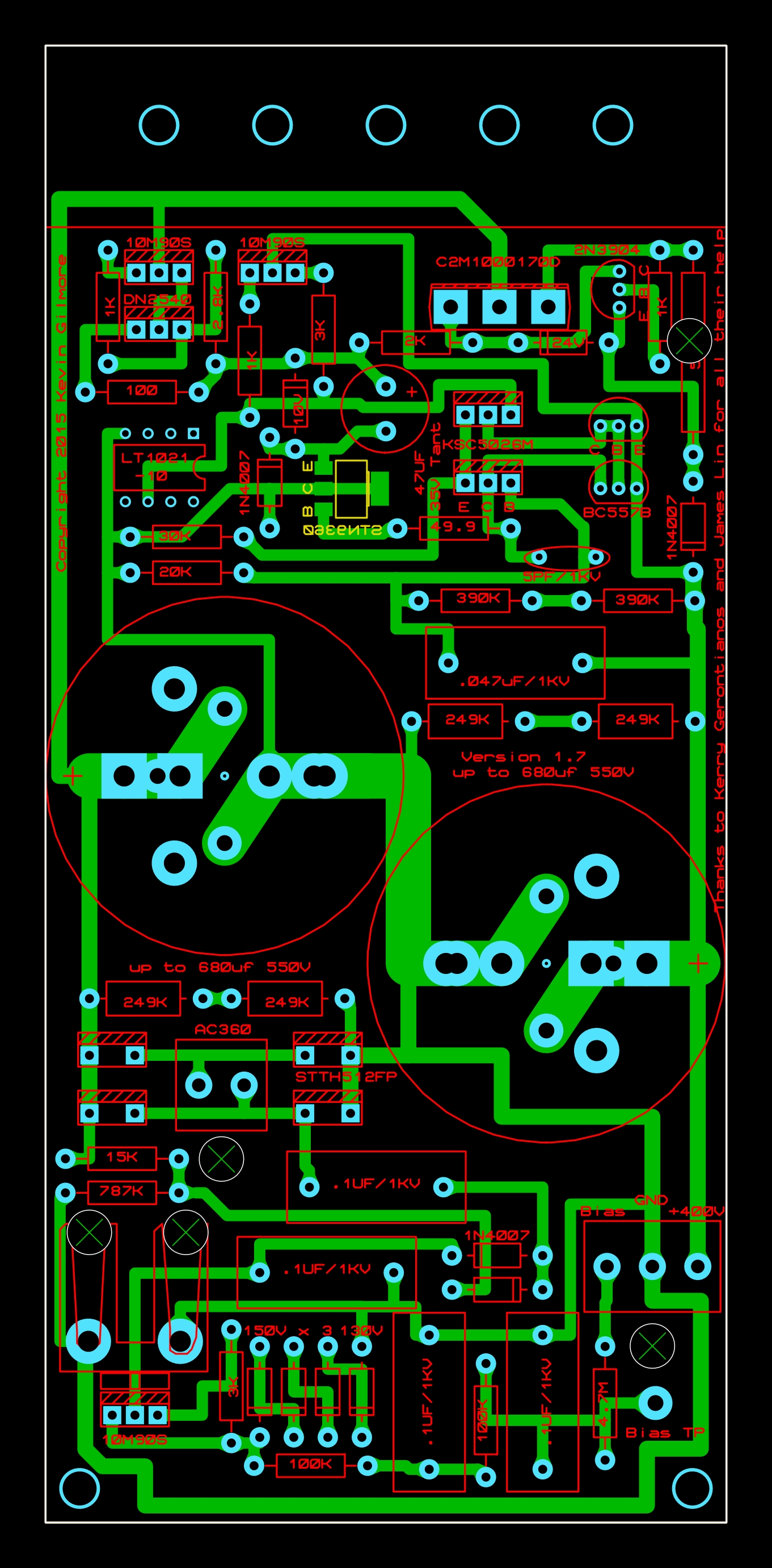
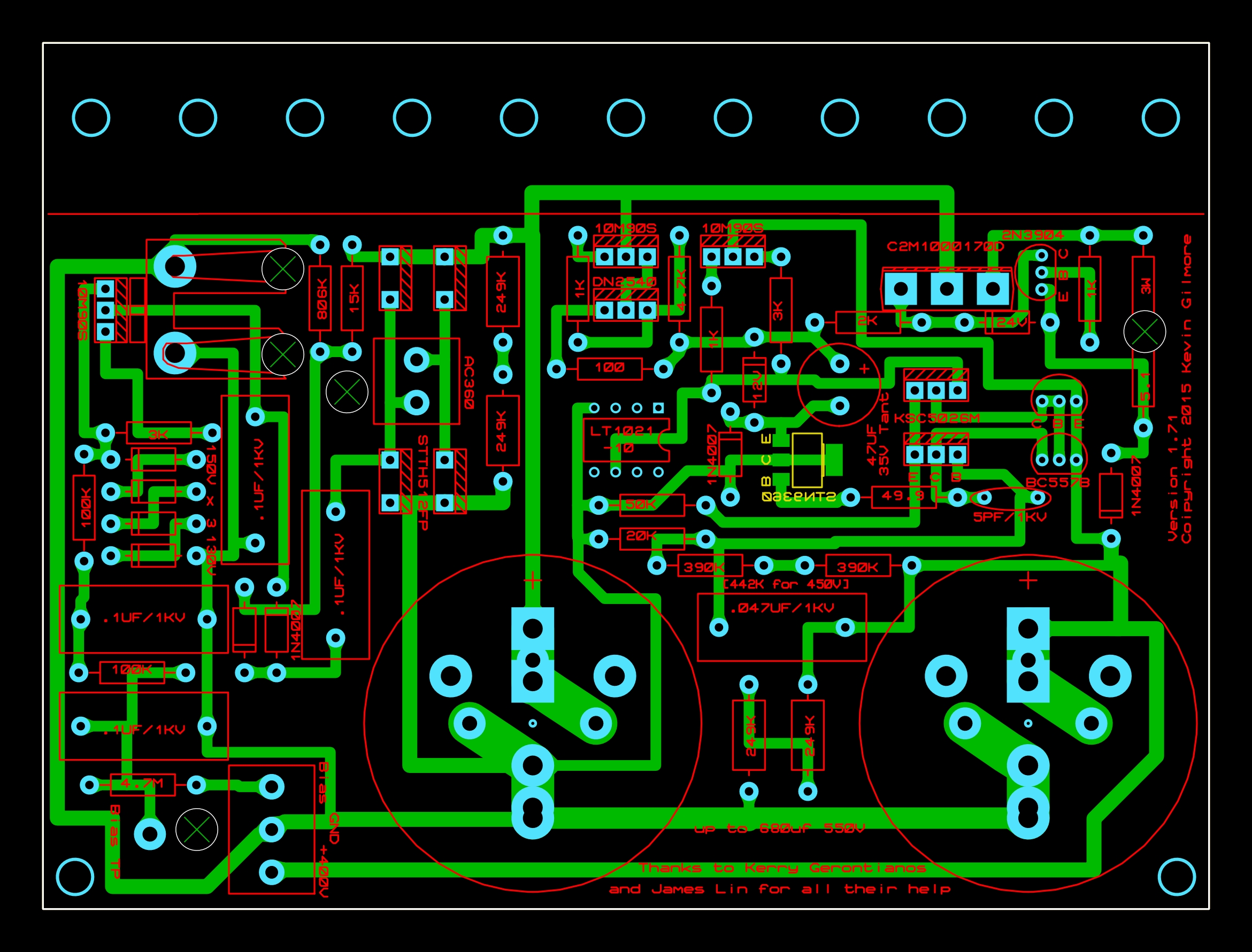
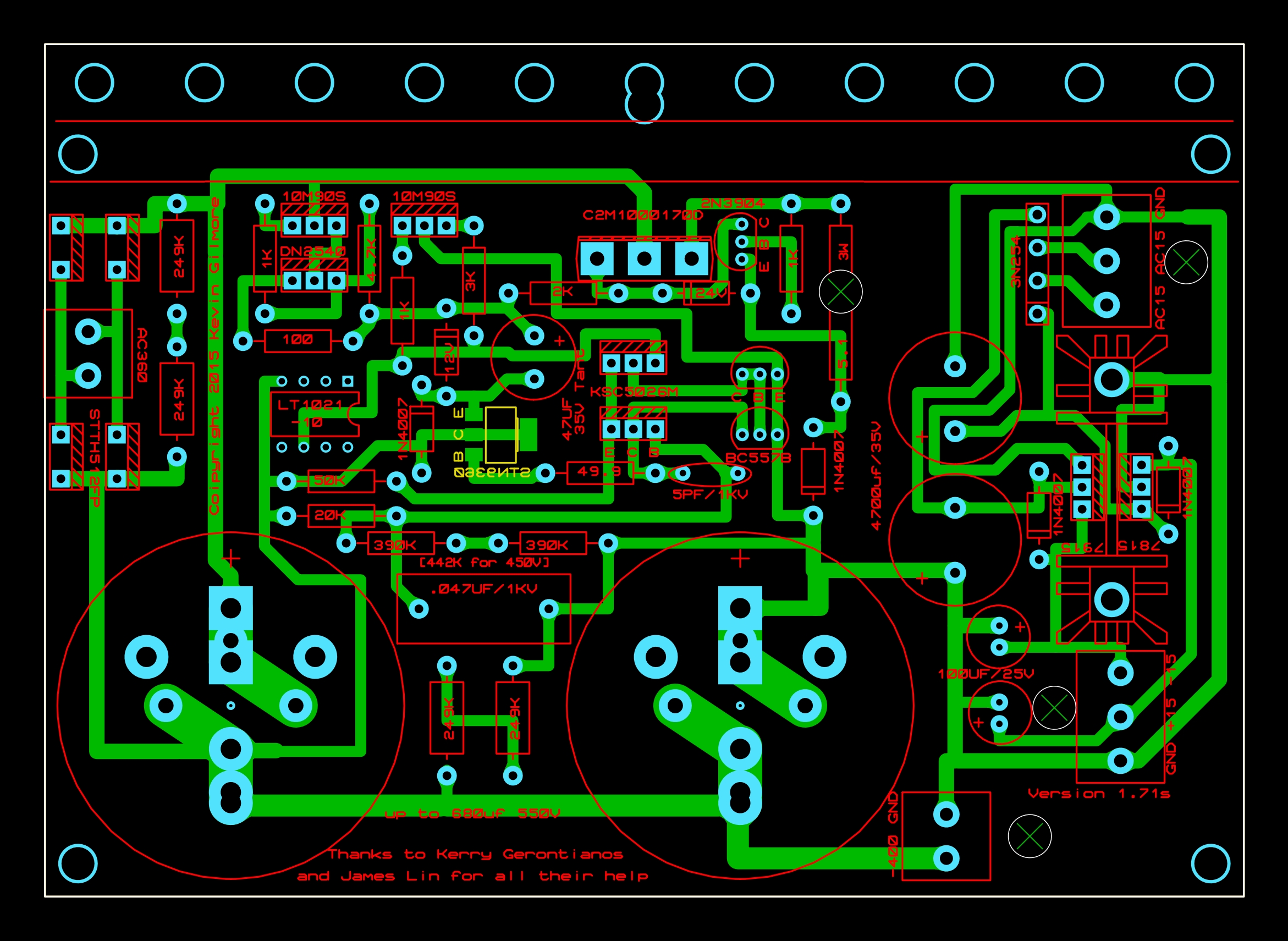
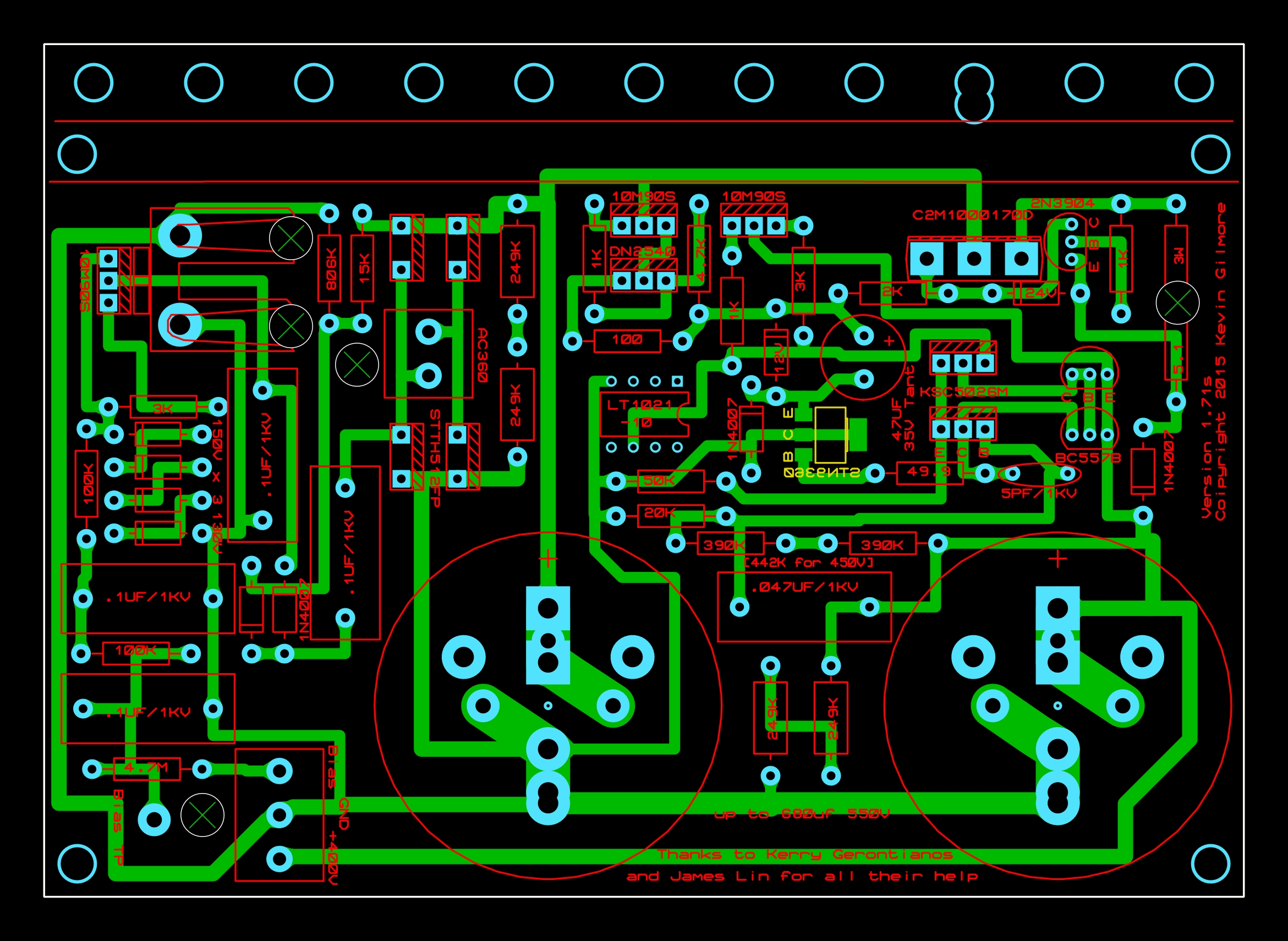
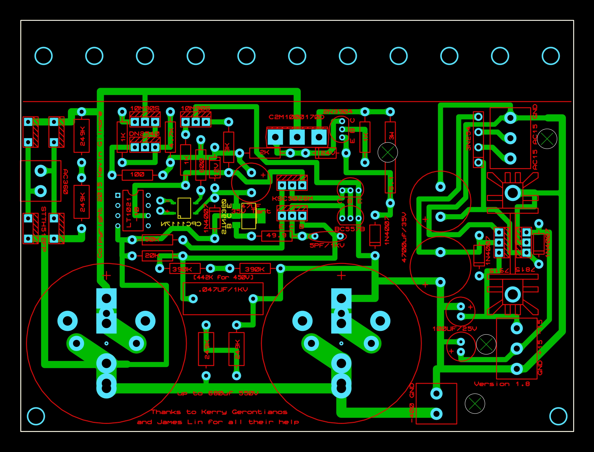
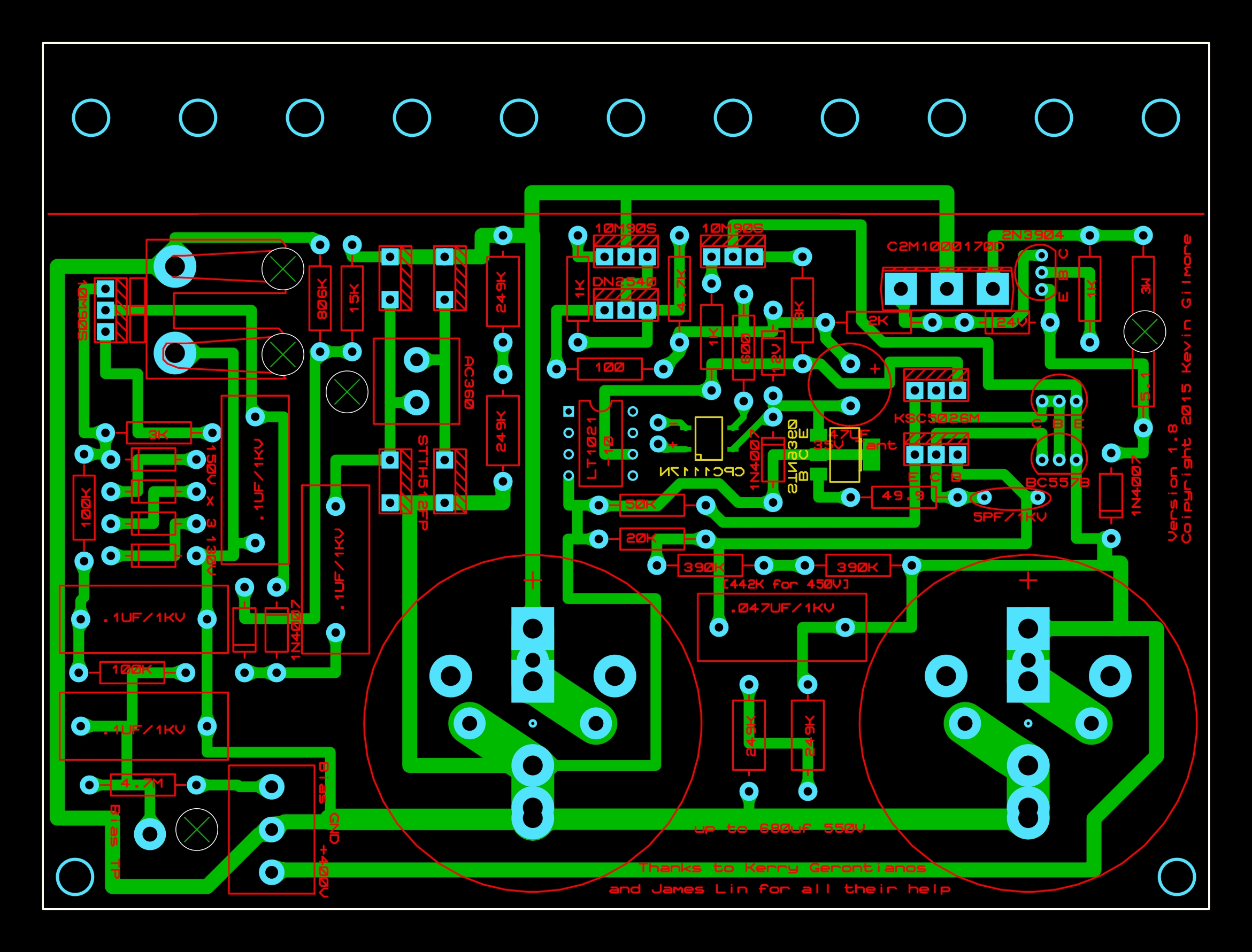
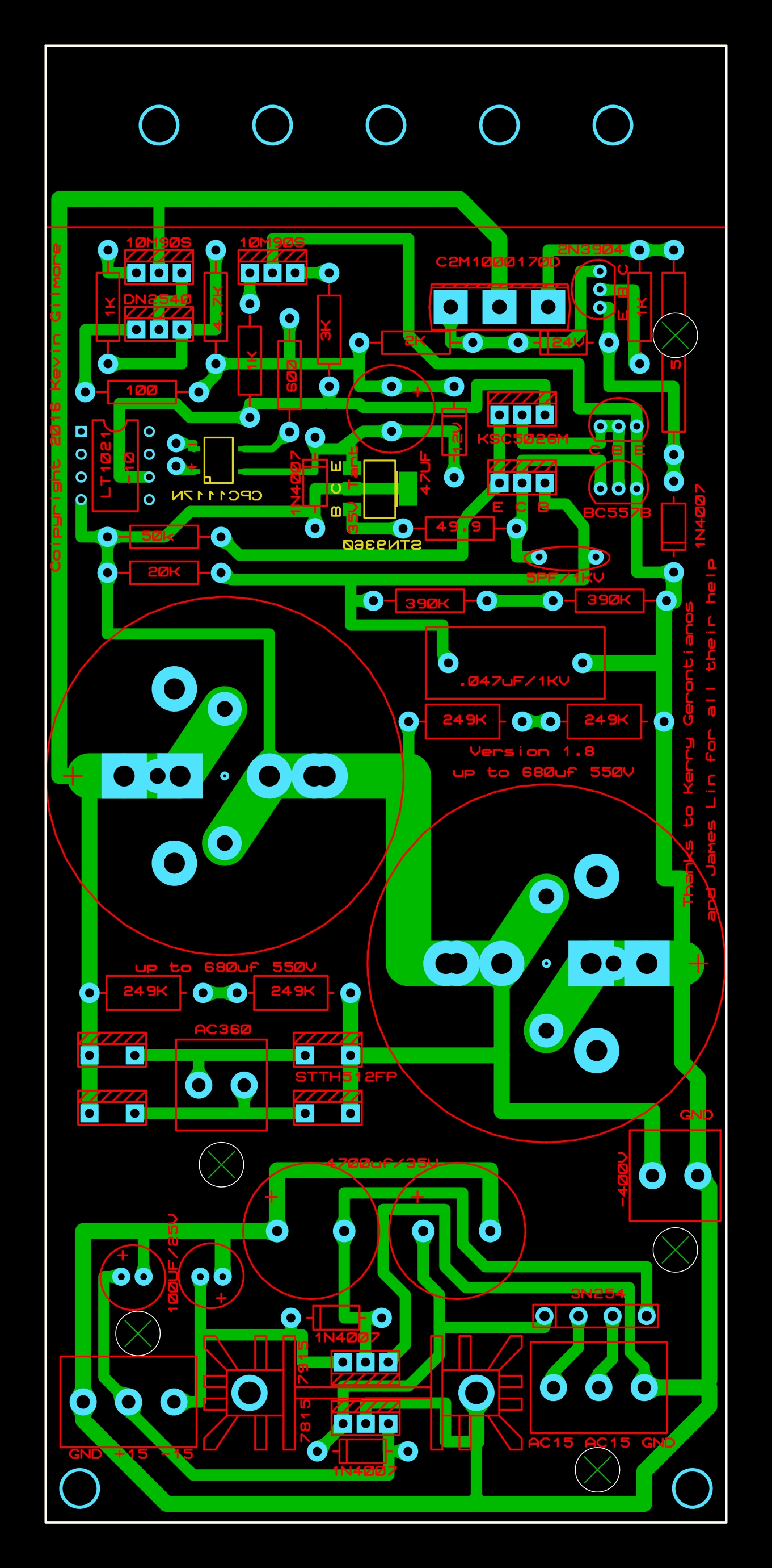
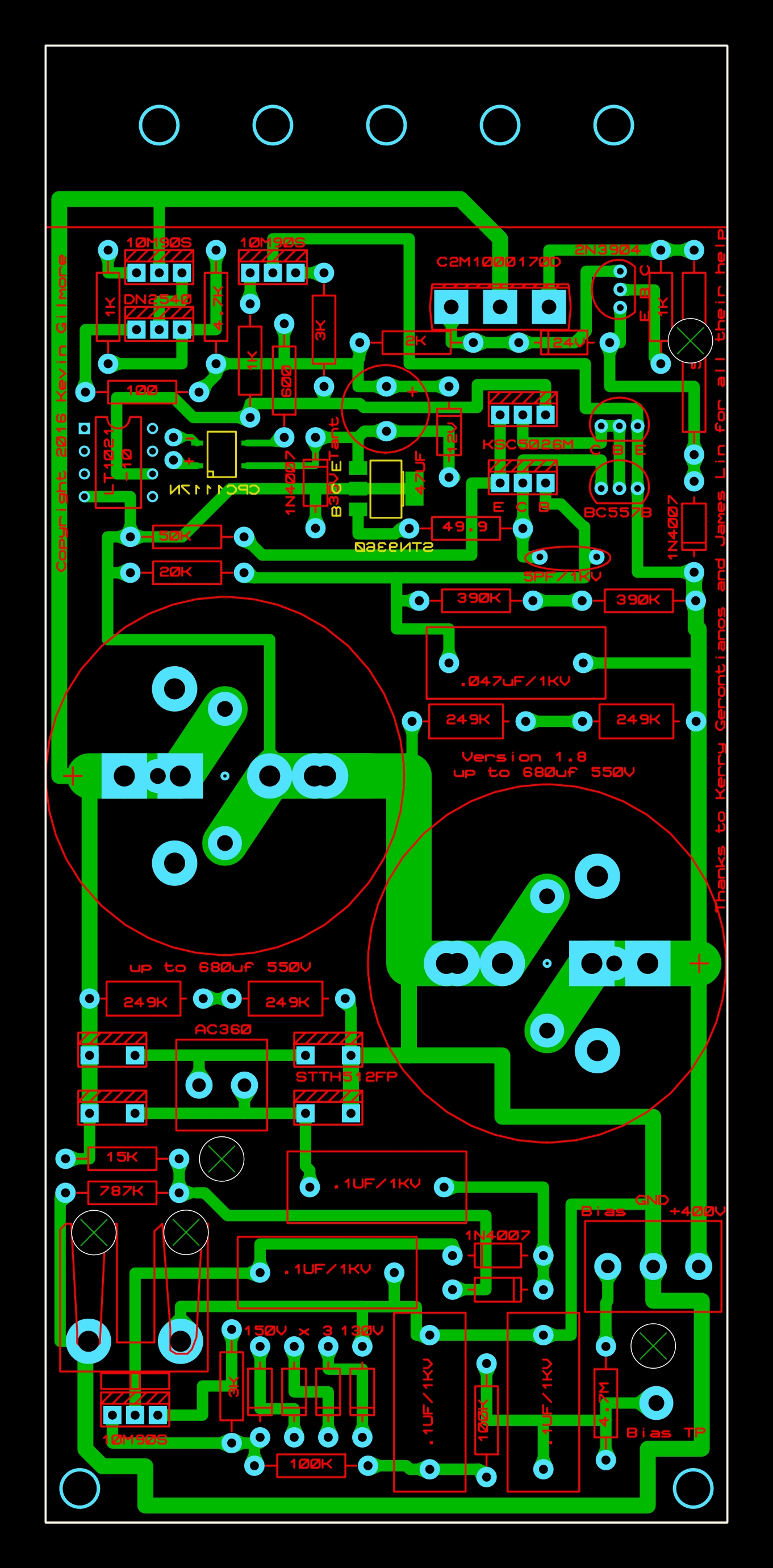
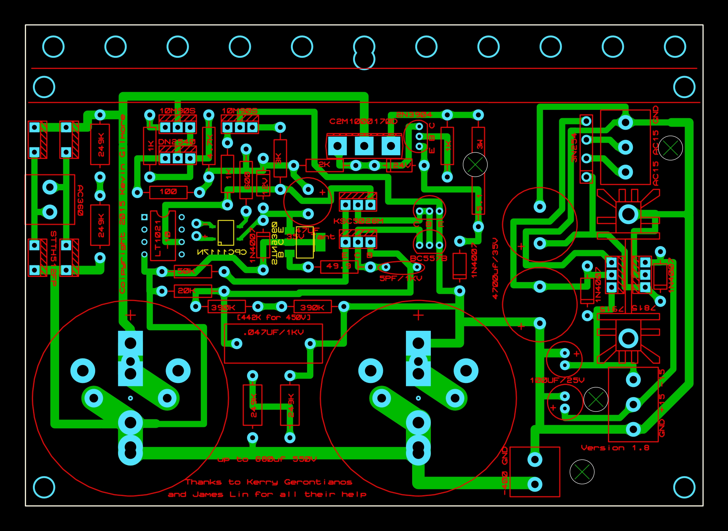
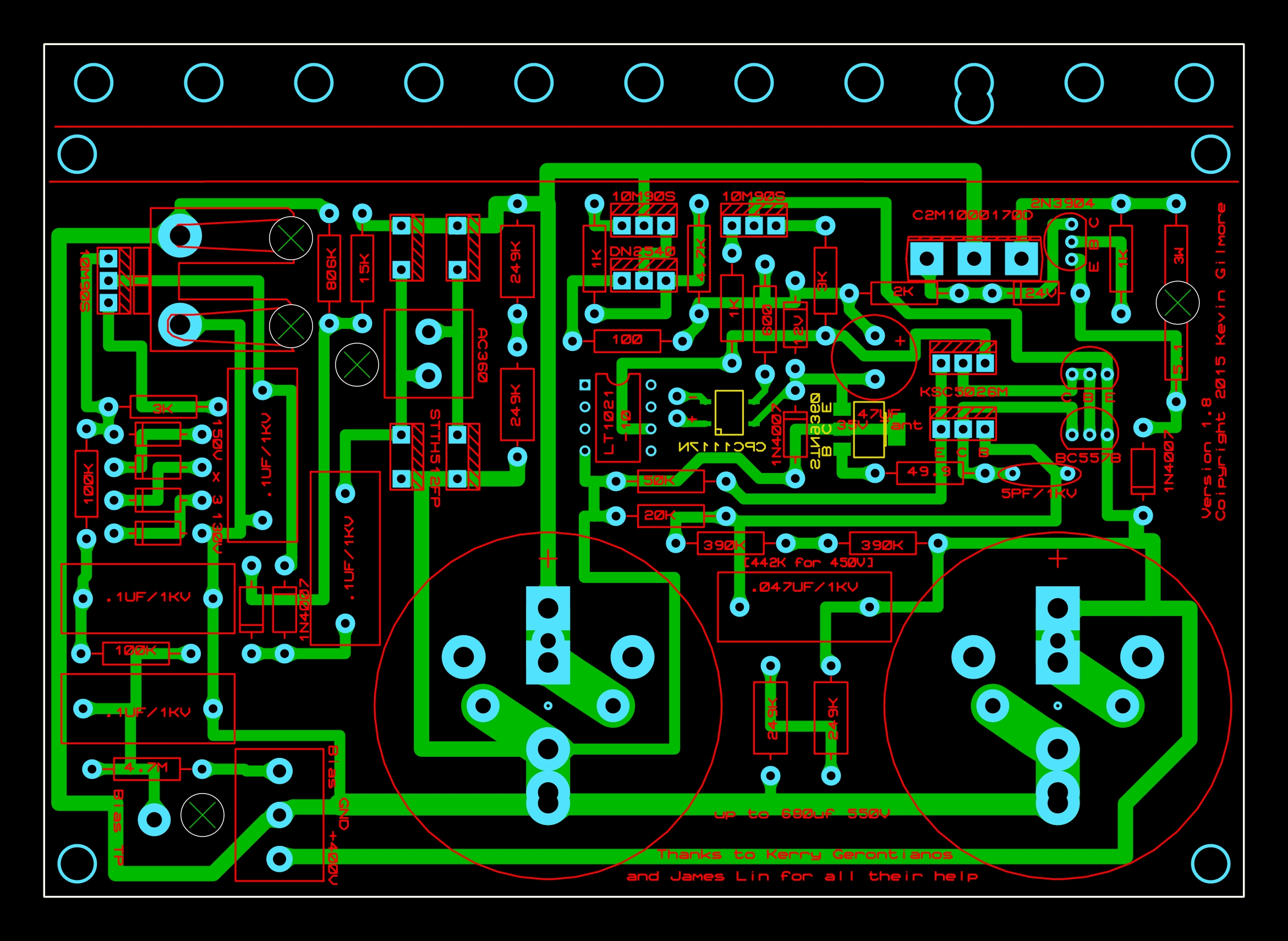
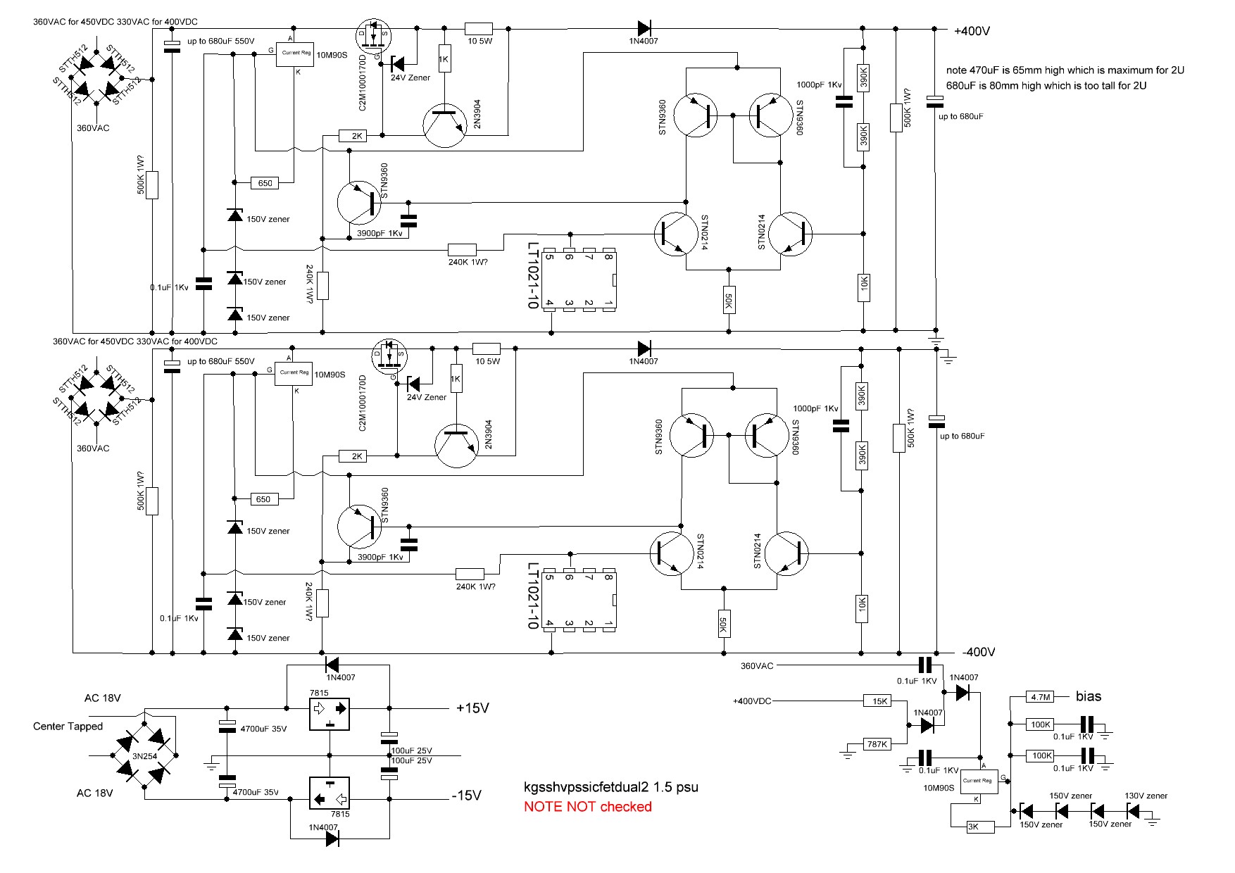
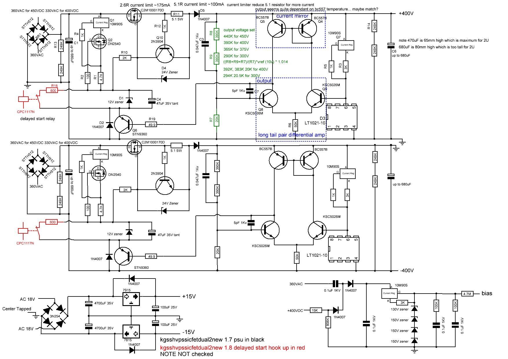
My guide to golden reference high voltage (grhv) variants Here is my attempt at documenting some of the different GRHV board variations. (this will be work in progress for sometime) feel free to private message me with any additions comments, corrections etc. please note the schematic for version 1.5 has been reverse engineered by me from the gerbers and may contain error(s). location of the gerbers: https://drive.google.com/drive/folders/0B_iJFfZStuVhSE5nOHBVdTByR1k golden reference filename naming guide fat - boards which are wider and have less height than the non fat variants L bracket mounting only same as the non fat variants. fat with S as the last character of the filename - boards which are wider and have less height than the non fat variants and the height is about 6.3mm less than the fat variant. these boards also feature more screw hole options for the mounting the pcb to the case including an option of not using an L shaped bracket and mounting the transistors directly to the vertical face of a heatsink/side of the case. a silkscreen cut line is included to guide removal of the L bracket mounting roles to facilitate direct transistor to heatsink mounting. dual - has both positive and negative hv supply with additional bias and both positive and negative low voltage supplies on a single pcb left - has a single negative hv rail and both positive and negative low voltage supplies right - has a single positive hv rail and bias no new in the filename version - 1.5 boards high voltage starts instantly board has high voltage VAC power. Topology is much simpler then version 1.7 and 1.8 and therefore not considered golden reference. new in the filename actual golden reference boards with extensive post pass transistor regulation. new without sw in the filename- version 1.7 high voltage starts instantly board has high voltage VAC power. new with sw in the filename - version 1.8 or later boards same topology as 1.7 but high voltage will not start until dc power supplied to the cpc1117n no dual and no fat in the filename - minimal width and quite high. NOTE placement of the screw terminals for input VAC can vary considerably depending on if the board is a fat, fat S or non fat. Overview of the versions It is the extensive post pass transistor regulation that marks the golden reference out from the other power supply designs as such version 1.5 and earlier not classify as a golden reference since they lack any post pass transistor regulation. No details of versions before 1.5 or version 1.6 could be found in the gerber archives. Apparently pre 1.5 versions had on board heatsinks and ground lanes but there gerbers and not available in the google drive archive. No schematic could be found for version 1.5 although after reverse engineering it was found that the circlotronps.pdf is similar in topology but modified to support 900V output. No bill of materials could be found for version 1.5 and it is not certain what is the power rating for the larger resistors. All versions have the pcb tracks on the underside with no tracks on the top. All versions have no ground plane ALL versions have bleed resistors to help discharge the high voltage caps although version 1.5 and a few variants of 1.7 use a single high power resistor and the rest two 1/2W resistors in series. All versions have the same basic voltage regulator based low voltage positive and negative supplies All versions have the same bias supply although v1.5 has different resistor values. ALL versions use a LT1021-10 voltage reference All the versions 1.5, 1.7 and 1.8 use a C2M1000170D pass transistor All the versions use a 10M90S pre regulator although version 1.5 controls it with a zener string and 1.7 and 1.8 control with a DN2540. 1.7 and 1.8 are almost identical in topology although 1.8 does not automatically start the high voltages. DC must be applied to the CPC1117N to start. note 1.8 does not have provision for screw terminals for the DC to switch on the cpc1117n. versions 1.7 and 1.8 have more post regulation using a second 10m90s (which is not present in version 1.5) after the 1N4007 protection diode. version 1.5 uses a 10ohm current sense resistor and versions 1.7 and 1.8 use 5.1ohm by default. version 1.5 uses a 10K resistor to ground in the 3 series resistor chain to decide the output voltage, 1.7 and 1.8 use 20K to get 400V output. The other 2 resistors in the chain are the same for version 1.5 and version 1.7/1.8 version 1.5 uses two stn0214 which are replaced by two KSC5026M in v1.7/1.8 version 1.5 uses two stn9360 which are replaced by two BC557B in v1.7/1.8 Known non golden reference boards which are variations or predecessors to version 1.5 and golden reference variants NOTE These have not been looked at in detail by me or fully reverse engineered. The cyclotron power supply series follows a similar evolution to the golden reference. earlier cyclotron psus (circlotronps.PDF) use a variation of version 1.5 topology with modifications to bring the output up to 900V. However since it lacks any post pass transistor regulation it can not be considered a golden reference these psus do not have new in their name. The later cyclotron power supplies have the words new or newver in their name on quick inspection of the gerbers appear to be modifications for 900V of the version 1.7 power supplies, have post pass transistor regulation and may be considered golden reference variants. The filename conventions follows the guide above with dual, single, S and SWS versions available. circlotronhvpowerdualnew.zip appears to be derived from the version 1.7 topology with a similar complement of transistors. On the underside of the pcb there are two additional stn0214 transistors compared to the version 1.7 plus 3 mount points for a total of 500V worth of smd zeners. circlotronhvpowerdualnewer2.zip ditches the zener string and introduces another stn3960 and includes sw and sws variations. The kgsshv8g.pdf power supply appears to be an predecessor version of version 1.5. There are very close similarities in topology including no post pass transistor regulation. Current sense is still controlled by a 2n3904. The pre-regulator is 10m90s controlled by a zener string and a quad of transistors like the version 1.5. However the pass transistor is two parallel fqpf8n80c. The control transistors are 2sa1486 instead of stn9360 and 2sc3840 instead of stn0214. Both types of control transistor are no longer in production and hence the conclusion this is older than version 1.5. Apparently these boards are classified as KGSSHV ------------------------------------------------ Version 1.5 boards ------------------------------------------------- predecessor to the golden reference with no post pass transistor regulation the board uses a single high wattage bleed resistor for each cap uses multiple stn9360s, stn0214s uses a serial zener string for to control the 10m90s pre regulator. LT1021-10 voltage reference based single sided board kgsshvpssicfetdual2.zip this has both positive and negative rails, a simple voltage regulator based low voltage positive and negative supply and 580V for stax headphones bias board size approx. width 152.7mm height 165mm silkscreen revision 1.5 kgsshvpssicfetsingle2.zip this has a single rail identical to the kgsshvpssicfetdual2 in topology and 580V for stax headphones bias board size approx. width 76.5mm height 165mm silkscreen revision 1.5 ------------------------------------------------ Version 1.7 boards ------------------------------------------------- considered the first known golden reference board version (given the lack of information on version 1.6) has extensive post pass transistor regulation. the board uses two serial bleed resistors for each cap uses a single stn9360s and multiple BC557B and KSC5026M uses dn2540 and 10m90s for stage early voltage control for the input to the c2m1000170D LT1021-10 voltage reference based double sided board kgsshvpssicfetdual2new.zip this has both positive and negative rails, a simple voltage regulator based low voltage positive and negative supply and 580V for stax headphones bias board size approx. width 152.7mm height 165mm silkscreen revision 1.7 kgsshvpssicfetsingle2new.zip this has a single positive rail identical to the kgsshvpssicfetdual2new in topology and 580V for stax headphones bias board size approx. width 76.5mm height 165mm silkscreen revision 1.7 single bleed resistor for each cap kgsshvpssicfetsinglenewleft.zip this has a single negative rail identical to the kgsshvpssicfetdual2new in topology and has a simple low voltage positive and negative regulators based supply board size approx. width 76.4mm height 165.3mm silkscreen revision 1.7 kgsshvpssicfetsinglenewright.zip this has a single positive rail identical to the kgsshvpssicfetdual2new in topology and bias supply board size approx. width 76.4mm height 165.3mm silkscreen revision 1.7 kgsshvpssicfetsinglenewleftfat.zip this has a single negative rail identical to the kgsshvpssicfetdual2new in topology and has a simple low voltage positive and negative regulators based supply board size approx. width 138.7mm height 103.1mm silkscreen revision 1.71 kgsshvpssicfetsinglenewrightfat.zip this has a single positive rail identical to the kgsshvpssicfetdual2new in topology and has a 580v stax bias supply board size approx. width 138.6mm height 103.1mm silkscreen revision 1.71 kgsshvpssicfetsinglenewleftfatS.zip this has a single negative rail identical to the kgsshvpssicfetdual2new in topology and has a simple low voltage positive and negative regulators based supply has more mounting options for the pass transistor, 4 holes for mounting to a case and can be used with or without an L shaped bracket board size approx. width 138.7mm height 98.6mm (slightly less height than the fat non S version silkscreen revision 1.71s kgsshvpssicfetsinglenewrightfatS.zip this has a single positive rail identical to the kgsshvpssicfetdual2new in topology and has a bias supply has more mounting options for the pass transistor, 4 holes for mounting to a case and can be used with or without an L shaped bracket board size approx. width 138.7mm height 98.6mm (slightly less height than the fat non S version silkscreen revision 1.71s ------------------------------------------------ Version 1.8 boards ------------------------------------------------- same topology as version 1.7 making this a golden reference board adds a cpc1117n and 600ohm resistor to control high voltage startup the high voltage will not start-up automatically. This negates the need for a external relay for delayed start-up and just requires dc power to be supplied to the cpc1117n (not present in earlier versions) for the high voltage to start-up. if you want the board to power up instantly simply omit the 600ohm resistor and cpc1117n and it will act just like the version 1.7 instant start boards. boards same size as the equivalent version 1.7 pcbs silkscreen 1.8 there does not seem to be a dual version of this board kgsshvpssicfetsinglenewleftSWS.zip this has a single negative rail almost identical to the kgsshvpssicfetdual2new in topology and has a simple low voltage positive and negative regulators based supply board size approx. width 76.4mm height 165.3mm silkscreen revision 1.8 kgsshvpssicfetsinglenewrightSWS.zip this has a single positive rail almost identical to the kgsshvpssicfetdual2new in topology and has a bias supply board size approx. width 76.4mm height 165.3mm silkscreen revision 1.8 kgsshvpssicfetsinglenewleftfatSW.zip this has a single negative rail almost identical to the kgsshvpssicfetdual2new in topology and has a simple low voltage positive and negative regulators based supply board size approx. width 138.7mm height 103.7mm silkscreen revision 1.8 kgsshvpssicfetsinglenewrightfatSW.zip this has a single positive rail almost identical to the kgsshvpssicfetdual2new in topology and bias based supply board size approx. width 138.7mm height 103.7mm silkscreen revision 1.8 kgsshvpssicfetsinglenewleftfatSWS.zip this has a single negative rail almost identical to the kgsshvpssicfetdual2new in topology and has a simple low voltage positive and negative regulators based supply has more mounting options for the pass transistor, 4 holes for mounting to a case and can be used with or without an L shaped bracket board size approx. width 138.7mm height 98.6mm (slightly less height than the fat non S version silkscreen revision 1.8 kgsshvpssicfetsinglenewrightfatSWS.zip this has a single positive rail almost identical to the kgsshvpssicfetdual2new in topology and has a bias supply has more mounting options for the pass transistor, 4 holes for mounting to a case and can be used with or without an L shaped bracket board size approx. width 138.7mm height 98.6mm (slightly less height than the fat non S version silkscreen revision 1.8
 7 points
 -
Finally, my mini T2 is completed. Just want to share my build experience and listening impression for those who are about to build one. Also, a huge shout-out for JoaMat, who conceptualised and designed the amp, provided me with invaluable tips when I was debugging my mini T2 and encouraged me to share my experiences here. -------------------------------- Pics or it didn't happen: -------------------------------- Build experience: Before this amp, I have built the Carbon and Grounded Grid, as well as quite a few dynamic amps including the SMD Dynalo. Overall, I am comfortable dealing with electrostatic amp voltages, but I have limited experiences working on dense and tiny SMD boards. I built the SMD Dynalo with a soldering iron, but this method was unsuitable for the Mini T2 due to the density of the components and the fact that I tend to use copious amounts of flux grease when I solder by hand - it would be too tough to clean the flux stuck underneath the tiny components. Therefore, I decided to solder the SMD parts by the solder paste and hot-air gun method. I used 1 set of mini T2 board, 3 through-hole GRHV boards and 1 delay board (warmup.zip). This amp is fast to build so long as you have a decent hot air gun (I got mine from Taobao for around 25 USD), a pair of fine tip tweezers and some patience. I used a stencil to apply solder paste on one side of the mini T2 board first, then populated all SMD components and used the hot air gun to melt the solder paste. It was quite satisfying to see the tiny parts drawn into their rightful place by the magic of surface tension. It took me about 1 hour to complete the SMD soldering for 1 side, so I'd say that this method is really efficient for the number of parts to be populated. The through-hole components and the tube sockets were populated next, and I used some terminal blocks for the power rail inputs. Just be sure to apply jumper wire for the -15V near the servo opamp. Otherwise, you risk seeing 400V at voltage offset, and frying some input tubes. The transformers I used were 130W and 87W for the HV and LV respectively. There is also a dedicated floating 12V winding for the delay board, and separate filament supply windings are used for the power tubes and input tubes for each channel. Voltage rails were pretty standard - +-15V, +220V, +400V and -460V. The warm-up time was set to 25 sec. There is no need to adjust for output current bias as in the Carbon or GG. The balance servo is activated by default, and all there is to adjust is the output voltage offset with respect to ground, and it can be easily adjusted so long as the potentiometers are soldered to the same side as the tube sockets. The amp runs cool. I used heatsinks that measure 7cm tall, 30cm deep, 5cm wide for each side of the chassis. At steady state, the amp module runs at 39 deg C, PSU runs at 35 deg C. In comparison, my 450V 20mA biased Carbon runs at 48 deg C with 15cm-tall heatsinks. Here are some errors I encountered here and the directions I took to debug. They are based on spice simulation by JoaMat. Hopefully, my tips can help builders who encounter similar issues as I did. 1. On power-up, offset voltage rises to 400V immediately after the HV kicked in. Check the jumper connection for the opamp -15v power supply. They are very short and can be easily missed. 2. 50K resistor explodes (either R11 or R12). It is likely due to an unconnected input tube or dead tube. Check input tubes and Q1A/B, Q4/5, Q11/12, Q3A/B of the same side. Also check tube sockets, because even the expensive ones can have loose connection on NOS tubes. 3. Q1A/B burns. This might not be easy to spot. The sign can be as subtle as a discoloration/fading of the silkscreen on the component surface, or a subtle exudation of flux around the collector pin of the component. This is likely due to a shorted input tube. ------------------------------ Sound impressions Take this section with a pinch of salt, for every DIY build is one-of-a-kind, and mine is no exception. For my mini T2, I used Duelund tinned copper wire as input cable, EIZZ stepped attenuator, STAX SPC earspeaker wires as output wires and a 5-pin socket ripped from a STAX extension cable. The headphone I used was the ES1a by ES Labs. I wish I had the Stax flagships to do this impression and comparison. The amp is fed by a AK4497 DAC, straight out of DAC and a coupling capacitor, bypassing any low-pass filters. For the following impression, I used decent tubes - Mullard xf2 EL34 as output, Brimar ECC88 as V1 and Sovtek 6922 as V2. Tubes do affect the sound significantly, and I will talk about that later in the discussion. My 450V 20mA bias Carbon with GRHV&LV will be a point of reference, as I am sure that this is a sound that many here are familiar with. It has the same volume pot as the mini T2 but SPC input wires and copper output wires. The mini T2 is full sounding with a natural tone. It has got a certain “WOW” factor that makes my carbon sound unimaginative in comparison. First off, the tonality of the mini T2 is warm and mildly bright such that the sound is airy but non-fatiguing, no matter how loud I cranked the volume up. The bass extends deep with a sufficient rumble where the track calls for it. The airy top end gives the amp a wide soundstage, that is paired with sufficient depth. Instrument and vocal placement are accurate and appropriate, without excessive forwardness or recess. Despite the soundstage being big, it does not sound hollow, because the music is full of details and creates a sense of well-layered space that is almost holographic. I have tested the amp briefly with other tubes and found that input and output tubes affect the sound most significantly. If input tubes have slightly mismatched sections, the balance would be too great to be zero-ed with potentiometer and balance servo. The small tubes I used are unassuming. Had I upgraded to better tubes, I guess the amp would sound better. Compared to the Carbon, the mini T2 sounds more organic, more layered and the mids are considerably warmer. It is also way more forgiving on bad recordings. The timbre sounds truer to life, soundstage is slightly larger, and feels like the music has more room to breathe. However, bass extension is not as deep as on the Carbon, and Carbon generally feels more analytical and snappier. To conclude, if there’s one word to describe this amp, it would be “fun”. It’s fun to build and definitely fun to listen to and roll tubes. I consider it as a step up from the Carbon when I use some decent tubes. Otherwise, this amp with standard new-production tubes would be at least on par as the Carbon.6 points
-
Appreciate the well wishes, everyone. I actually had a pour of that birth year BenRiach decant you gave me. It was quite tasty, thanks again.5 points
-
Death - ...for the whole world to see an undiscovered black punk band from detroit. subject of the documentary “a band called Death”
3 points
-
3 points
-
Fermented meat.2 points
-
More mid-fat snow testing in preparation for a longer ride tomorrow morning.
2 points
-
Deck Lemon Cake and Proper Tea
2 points
-
2 points
-
1 point
-
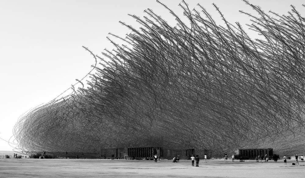
Xavi Bou’s Portraits of Birds in Flight https://www.audubon.org/news/how-xavi-bou-makes-his-mesmerizing-portraits-birds-flight
1 point
-
Last night's show is up:1 point
-
There are some negative reviews of the Sabrent box, so it makes me a little suspicious (it is also listed as out of stock on their website). I'd definitely have a backup of the data and test the RAID array if I got one – it doesn't seem to have any software so it's really up to your built-in macOS drivers. Also, there are some complaints the fan is loud. Their product page links to a different product on Amazon, the non-RAID version (DS-4SSD instead of DS-4RSS). I'm going to surmise that the RAID variant was too problematic so they discontinued it and they are selling the simpler, cheaper variant for now – one of the Amazon comments mentions using Windows Storage Spaces to run software RAID, but I'm not sure I'd rely on it. TL;DR: There are a bunch of low-priced "RAID" devices with poor reviews online... they probably use the same cheap JMicron controllers and they don't have the performance or data integrity of real hardware RAID devices (which usually cost hundreds of dollars). I think I'd get this instead – run 2 large 2.5" 5TB drives in RAID 1 for a total of 5TB and use this fanless enclosure because I trust OWC more than the other manufacturers: https://eshop.macsales.com/item/OWC/MEMDC2KIT/1 point
-
Foveon news1 point
-
I made etouffée, but didn't take pictures. Then I drank heavily and watched true blood til I passed out.1 point
-
Fried soft shell crab po'boy and Zapp's voodoo chips and king cake for dessert. Laissez les bons temps roulez!
1 point
-
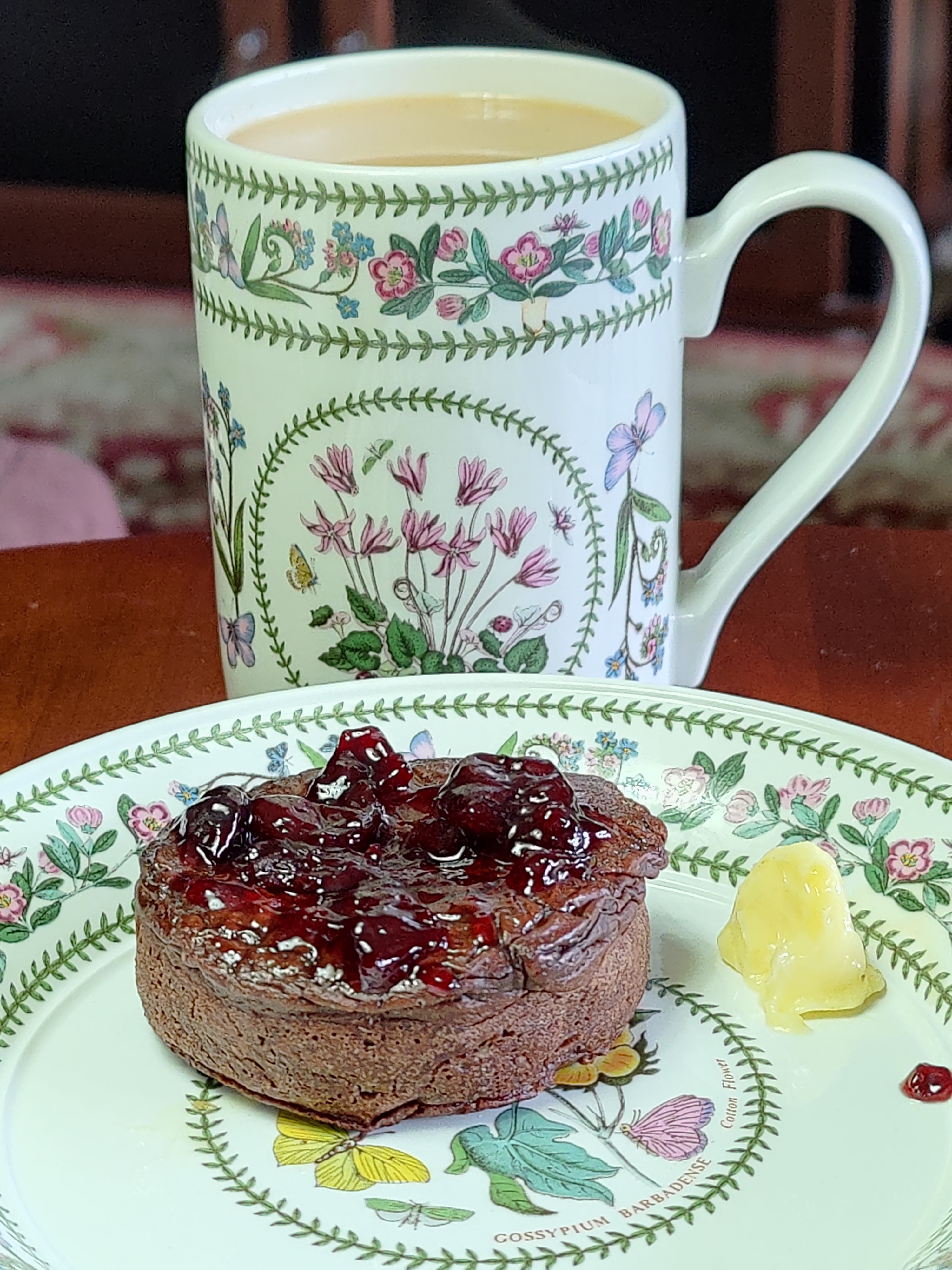
Homemade Hot Buttered Chocolate Crumpet with Black Cherry preserve.
1 point
-
I've dreamt of strumpets but never crumpets. I've had this brand before and they are pretty decent.1 point
-
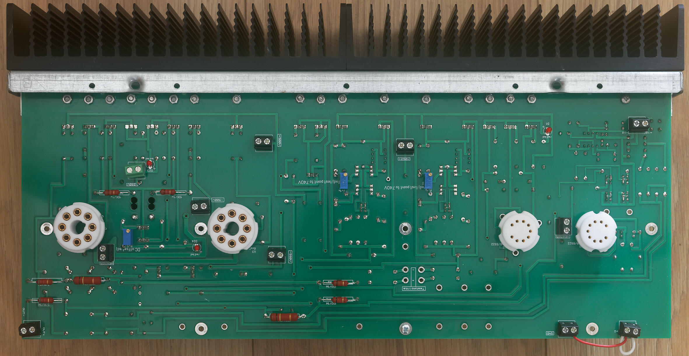
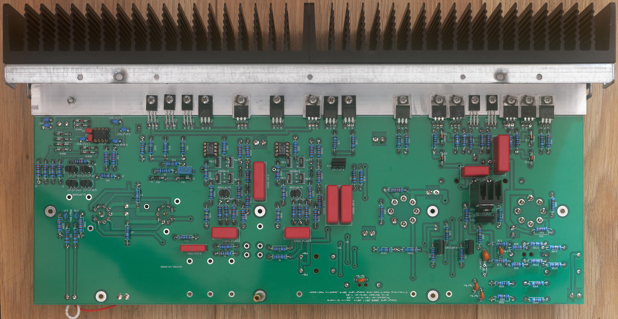
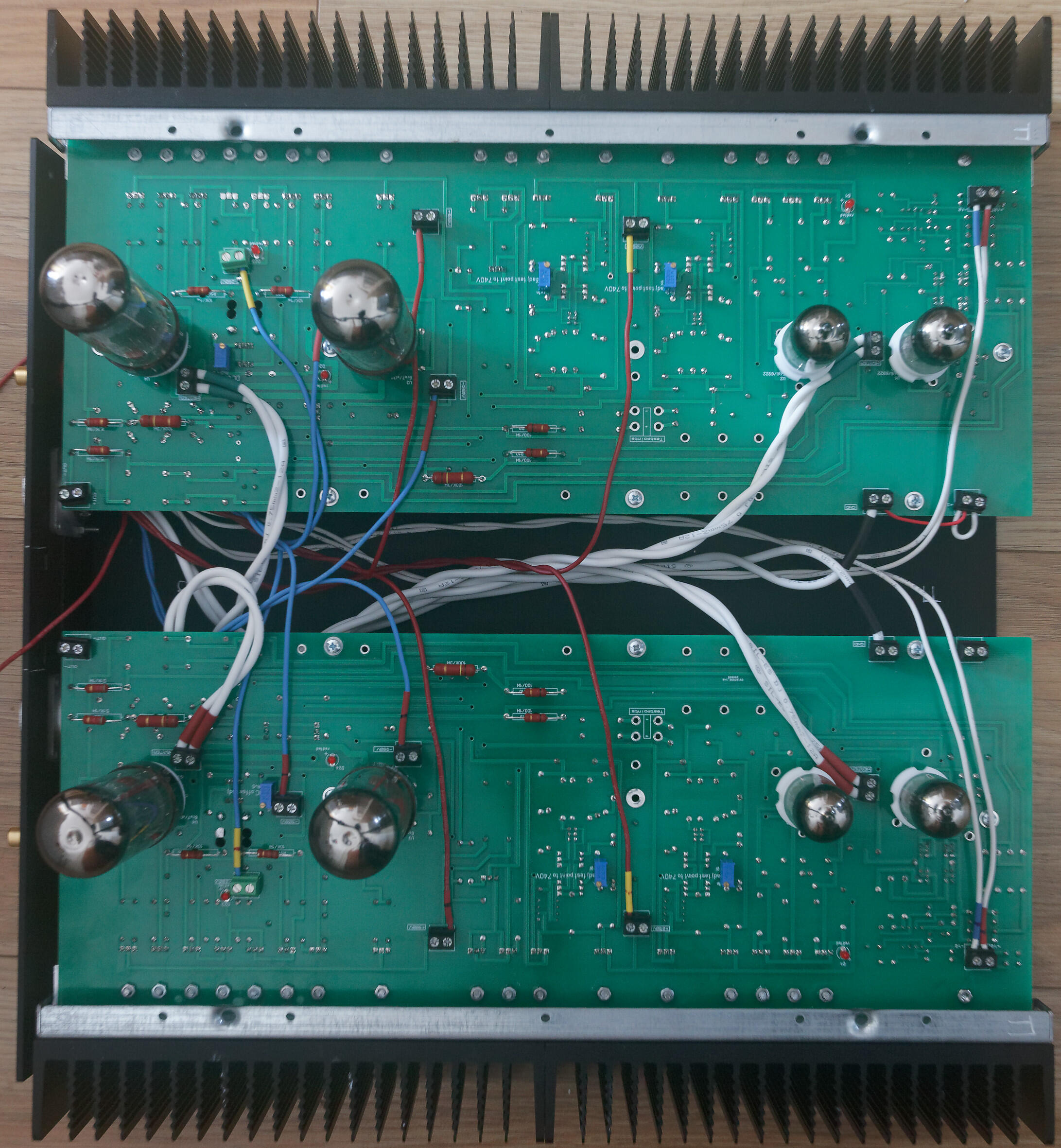
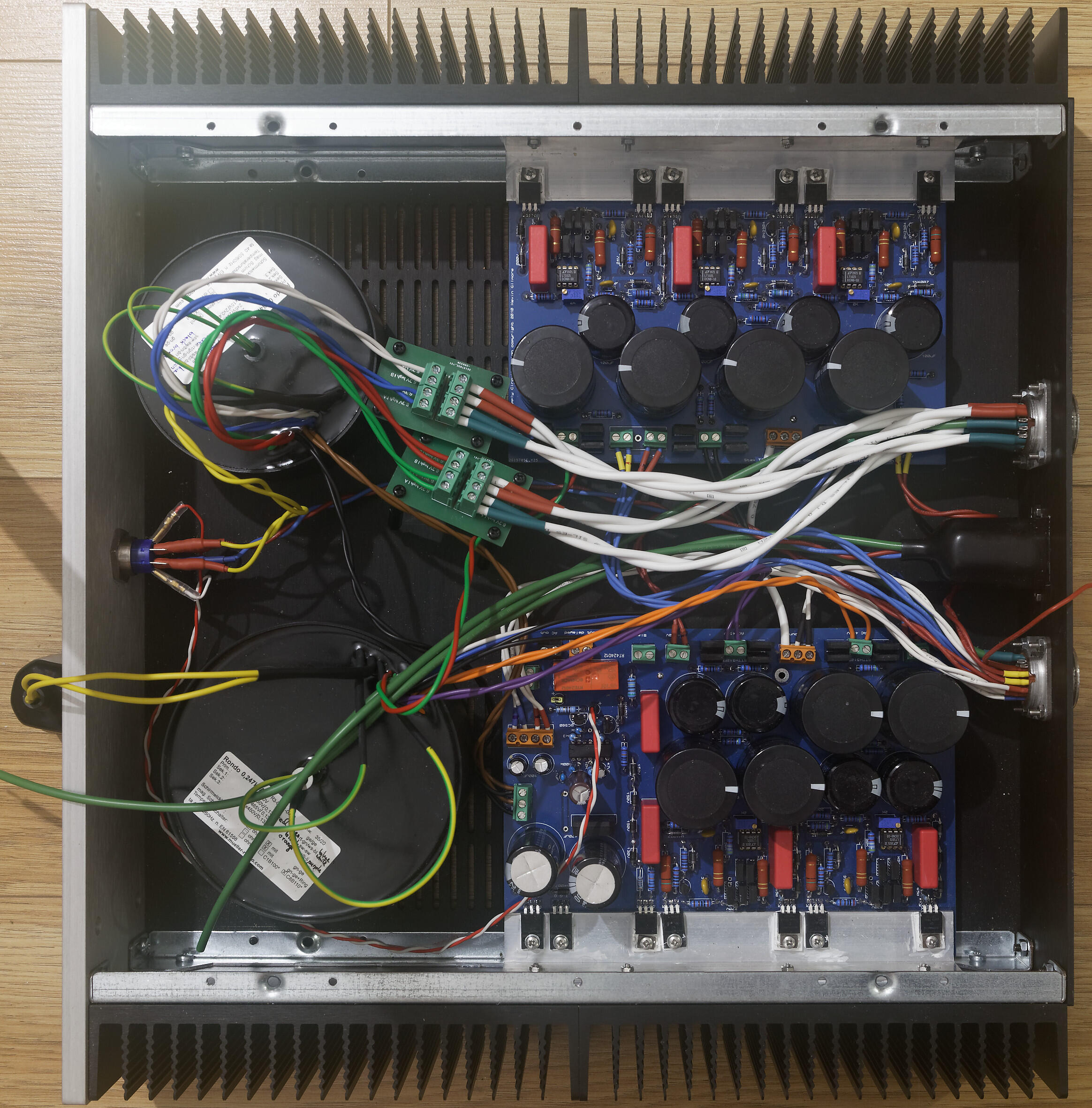
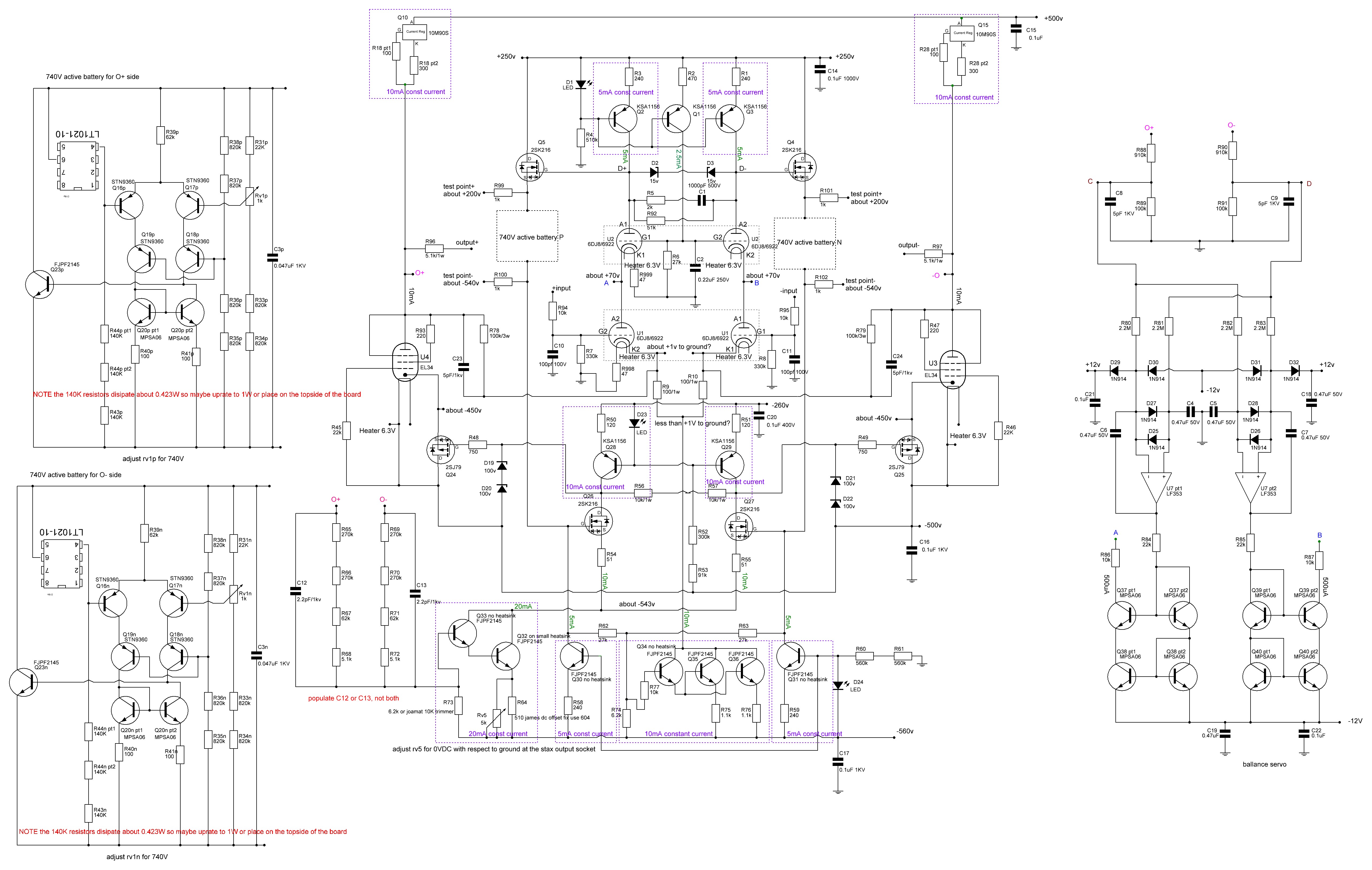
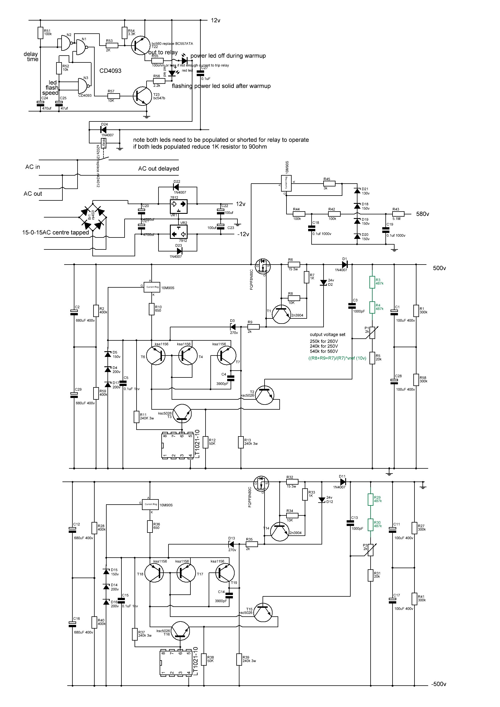
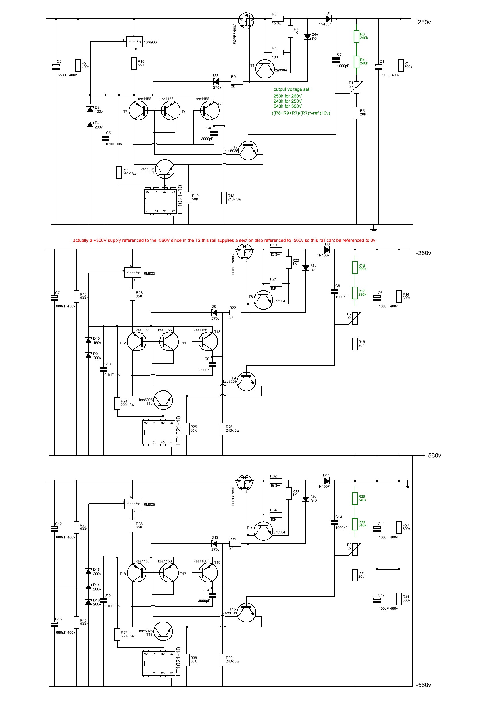
It might be a little premature but I think I now have a working T2 using a modified version of joamat's staxt2nc3fdh7 amp files and kgsshv dc supplies.... Initial startup looks good. Channels started up seperately. Heater transformer running at full voltage. High voltage transformer on a variac. virtual batteries within 100mV of 740V before any adjustment. DC balance between + and - sides of a channel <1V without any adjustment, all 3 leds lit on both channels. once my hands stop shaking I will take a few photos... I have been dreading switch on... in the meantime here's a few build photos of a finished amp channel top and bottom, the amp and psu I modified the delay circuit on one of the psu boards to use a relay instead of the now unavailable solid state relay. I modified the amp boards so that 1. they fit into a 400mm deep chassis, hifi 2000 dissipante chassis. 2. they have screw terminals for all connectors on the top.. (less neat but easier for testing and rebuilding) 3. all resistors of 1W or more go on the top of the pcb with a drill hole under for increased airflow 4. groundpane is between 1.1mm and 1.3mm from any solder point 5. pcb is cut in half so each channel can be built, tested and mounted independently, 6. solder points for pot and input jacks removed and replaced with screw terminals. 7. silkscreen has instructions for adjustment of pots 8. mpsw06 transistors replaced with mpsa06 9. small standalone heatsink for Q34 FJPF2145 in the 20mA current source darlington pair has drill holes in the pcb by the fins for enhanced airflow. 10 all components have schematic numbers included in the silkscreen 11 leds and adjustment pots mounted on top side of pcb like the original T2 12 removed the bias input and 5.1M resistor (since the kgsshv psu already has the resistor in the bias section) I will be happy to release the gerber files of my modification once I am certain the amp is reliable For the build: wima film capacitors, mixture of koa cm1/2 and xicon 273 series 1/2W resistors, for higher wattage vishay pr02 and pr03 All resistors, diodes, zeners raised from the pcb. pcb 2mm with 2oz traces. All 1/2W resistors matched to 0.1% or better at 1khz on a good LCR meter between + and - sections of an amp board AND between left and right channels. all non psu and psu decoupling caps matched to better than 1% at 1KHz on a LCR meter between + and - sections of an amp channel AND between left and right channels. (except for the pF caps which are just too small to measure accurately). all leds and mpsa06 transistors matched on a dca75 curve tracer between + and - sections of an amp board AND between left and right channels. all zener diodes matched to within 1% or better between + and - sections of an amp board AND between left and right channels. separate umbilical cords for AC heater power and DC voltages all internal wiring 1KV silicon all signal wires will be cardas chassis wire volume pot tkd 2500 series left to do install rca signal wiring, volume pot and stax output socket test with signal generator and measure distortion etc collapse from T2 build anxiety drill top of case for valve sockets clean up wiring pray to the god(s) of electronics sort out grounds on psu post moar pictures Here is the schematic for the staxt2nc3fdh7 NOTE this is my reverse engineer based on the pcb and the original T2 schematic and has not been checked by anyone. ( as far as possible component labels reflect the original T2 component labels. In the case of 2 components replacing a single component in the original T2 the components are now labeled Xpt1 and Xp2. In the case of additional components no present in the original T2 they start with the number 9XX. In addition both batteries are shown and the the components labeled with a Xp for the O+ side battery and Xn for the O- side battery. Note the 140K resistors in the virtual batteries dissipate 0.423W each and I found xicon 1/2W 273 series discoloured and drifted by about 1% after about 6 months heavy use when placed on the underside of the pcb. So you may want to think about 1W resistors or place the resistor on the top side of the pcb. psu low voltage, bias, +500V -500V and hv delay reverse engineered from pcb and original schematic. not checked by anyone. psu +250V, -260V and -560V reverse engineered from original schematic and pcb not checked Note psu schematics changed 22/08/2022. Thank you to Rinat for spotting an error on the current path around the 3900pF cap.
1 point