Pars
-
Posts
8,601 -
Joined
-
Last visited
-
Days Won
7
Content Type
Profiles
Forums
Events
Everything posted by Pars
-
Damn! RIP Charles! Sent from my iPhone using Tapatalk
-

and now for something completely different part 3
Pars replied to kevin gilmore's topic in Do It Yourself
That was quick Kevin Sent from my iPhone using Tapatalk -
I had just run across them on diyaudio and hadn’t looked at them closely. Sent from my iPhone using Tapatalk
-
JFETs... anyone look at ZVP3310 and ZVN3310 as possible J74/K170 replacements?
-
B grade if going with Linear Systems. Most of the Toshibas used were BL grade. And yes you might be ahead to just use the current boards rather than hunting the stuff down for these. Sent from my iPhone using Tapatalk
-
Agree with sbeylo. The gain resistors in your silk above are the 200k/10k and cap next to them. Some of the sand shown could be problematic: 2sa1145/2sc2705 2sa1358/2sc3421 2sa1349/2sc3381 Sent from my iPhone using Tapatalk
-
I don’t have the schematic handy, but will try to answer what I can 11 is the standard gain. Without the schematic, I can’t tell you which resistors though Use 1.7V unless you feel like calculating resistor values to arrive at the design CCS currents using something else That should be fine. Use something that fits the board Without the schematic, hard to say. If that shows the MPSWs you showed above, that could be a problem. Arrow may still have some. The nearest equivalent is the PZTA06/56, but those are surface mount. Also, I would assume that Kevin was using something more like MJE or MJF15030/15031 for the output devices? The 7815/7815 are there so you don’t have to use OPA445 for the servo opamp. If you omit them, you’ll need an opamp that can handle your +/- rail voltage. Also, I wasn’t sure if the lil knight boards were the Super Symmetry? Sent from my iPhone using Tapatalk
-
Happy Birthday! Sent from my iPhone using Tapatalk
-
and now for something completely different part 3
Pars replied to kevin gilmore's topic in Do It Yourself
Changed out to the 10K TKD from my ss dynalo. Huge difference (for the better). Will need to do some more listening and comparing to the Dynafet. -
Nm on question regarding the rotary switch. What kind of beast resides in there? And how are you actually doing the gain switching (and rumble filter)? Relays?
-
and now for something completely different part 3
Pars replied to kevin gilmore's topic in Do It Yourself
The one I used was 81-RDEC71E476MWK1H3B. From the spice model I built, I only see 5Vdc across this cap. It isn't marked polarized on the board, so I used ceramic instead of tantalum here. I don't think I ever saw a BOM here, so don't know what Kevin had in mind. From the silk markings, it would seem ceramic. -
and now for something completely different part 3
Pars replied to kevin gilmore's topic in Do It Yourself
Yes, the 1 ohms are wirewound, from this post. I was thinking about using Mills MRA5s here. -
Looks nice Marc! I might have not spelled Phonograph out (Phono), but otherwise. As for the knob and its 4 positions, not sure how you are doing that with a knob? How do you select MC + rumble on for example? The knob with a dot might look better than the line.
-
and now for something completely different part 3
Pars replied to kevin gilmore's topic in Do It Yourself
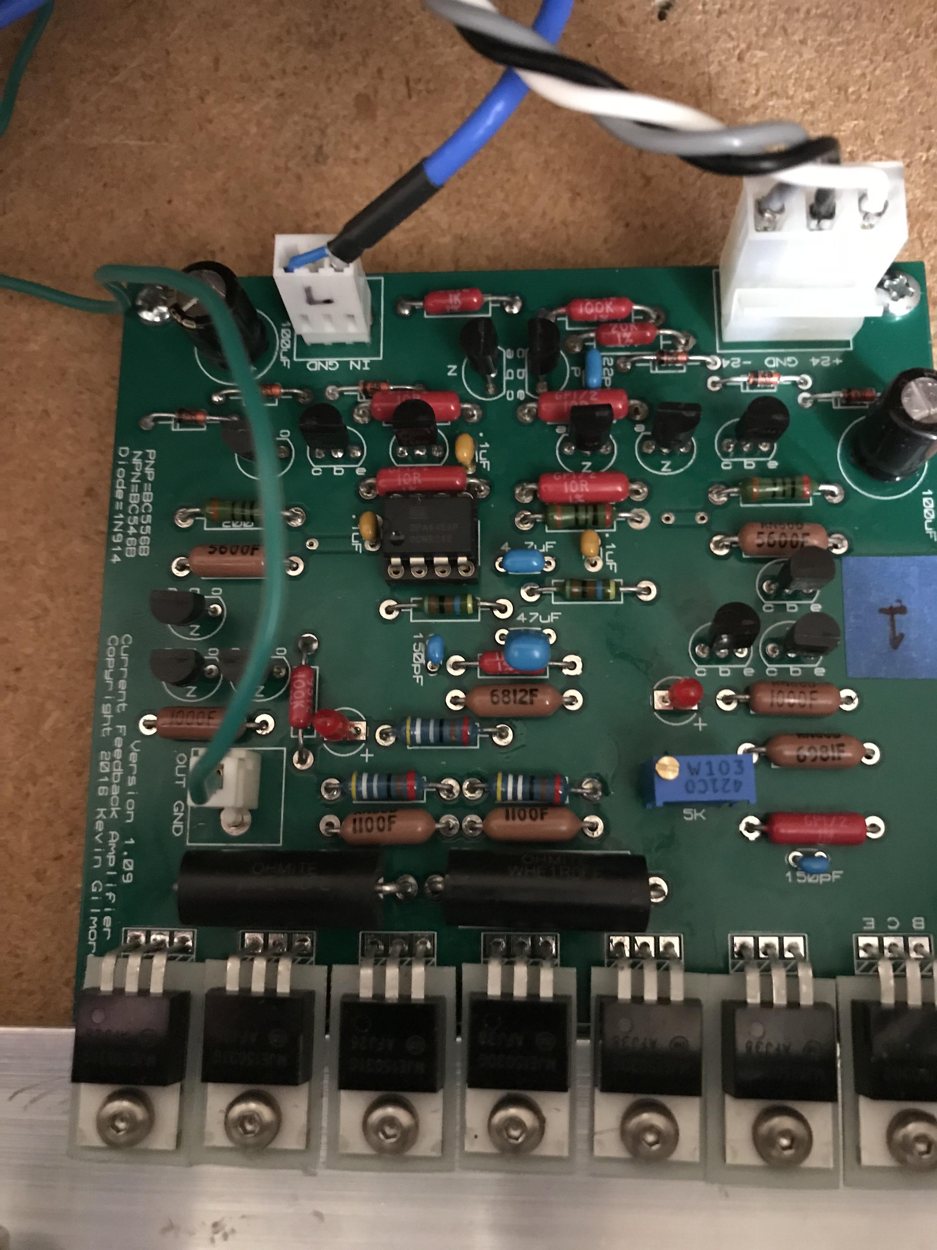
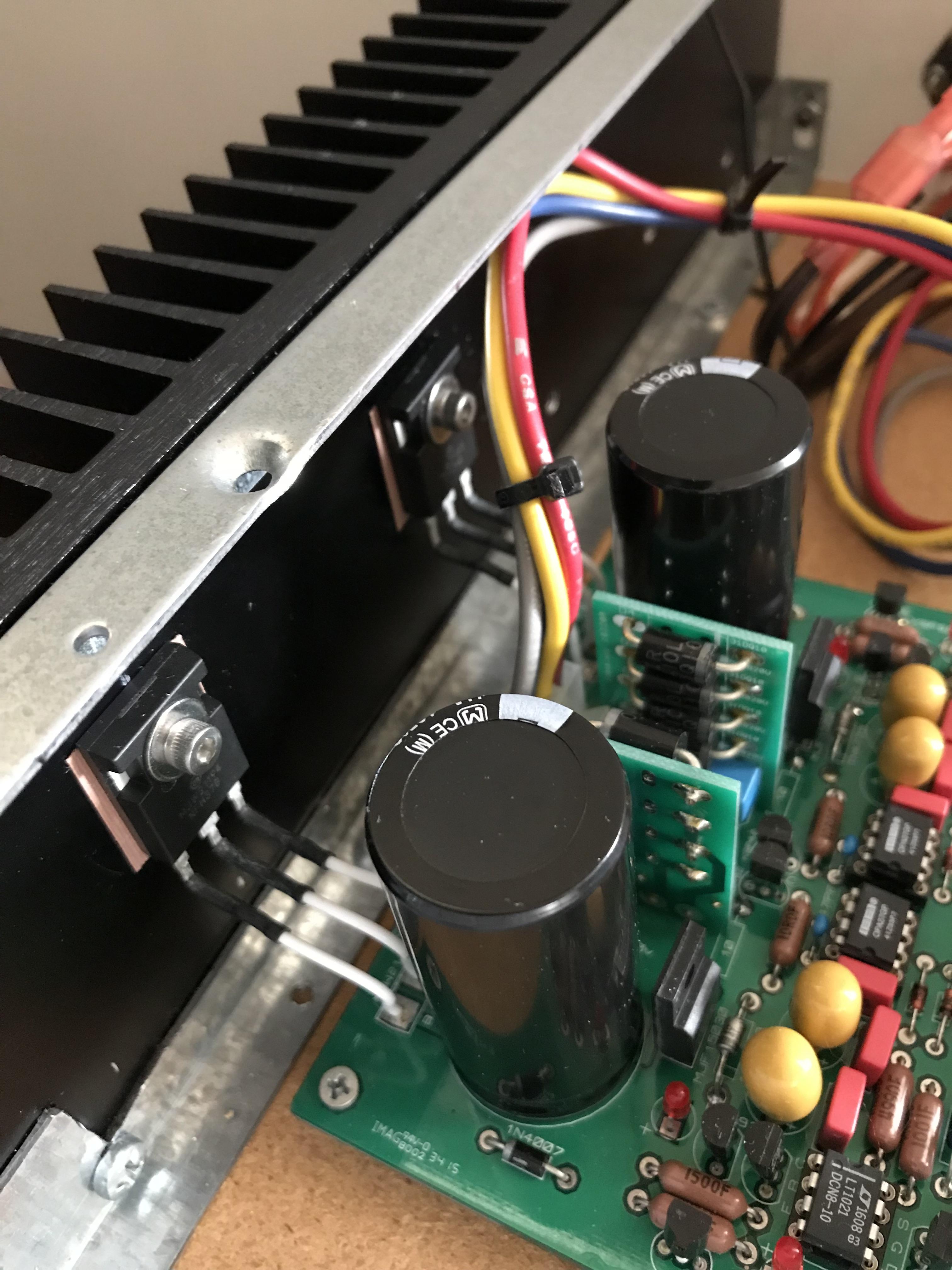
Looks nice Michael, and agreed on the socket. Having it machined to recess into the front panel might look better as well, but looks great for a prefab case! Here are a couple of pics of mine so far (the usual not even close to being done ) I took Kevin's suggestion and wired the pass devices off to the heatsink for the GRLV.
-
Happy Birthday!
-
and now for something completely different part 3
Pars replied to kevin gilmore's topic in Do It Yourself
Thanks. Like Michael has experienced, even with matching (hFe and resistors), the DC offset without the servo is 66mV (for me), consistent in both boards. The servo brings it down to ~1-2mV. Biasing is at 200mA across the 1 ohm resistors. Q21 (the MJF15030 driven by the 7K resistor and the pot) seems to be running rather warm, but I'll need to recheck that. Overall, the amp doesn't run as warm as the Dynafet does. Running it at +/-30V currently, GRLV. Sound wise, from a short listen, this didn't sound as "fast" as I was expecting. It still sounded very good. The highs perhaps sounded a little recessed. This is all with the 25K pot. I'll try it with a 10K Alps today and see what difference that makes. Damn easy to build and get running though; pretty much came right up. As long as you don't make any errors stuffing the board, it works. Yes, I'm looking at you Dynafet -
and now for something completely different part 3
Pars replied to kevin gilmore's topic in Do It Yourself
What would the sonic effect be of running a 25K pot with this? It is what I have (TKD) in my DynaHi/DynaFET and I was planning on running these boards in that. I know you usually spec a 10K. Thanks! -
Happy Birthday!
-
Happy Birthday!
-
That one might work. Also I came across this as a replacement: PBHV8540Z
-
and now for something completely different part 3
Pars replied to kevin gilmore's topic in Do It Yourself
Tossed together an LTSpice model for this (warning: I'm a Spice newbie/hack) CFP spice.zip -
I wish I could use modelling software like that
-
RIP to David, Della, et al And RIP to Arnie Nudell (Infinity)
-
There is a thread about a Wayne-designed Pass Labs head amp on diyaudio right now, with pcbs being available. Sent from my iPhone using Tapatalk
-
I think you meant Schottky. They supposedly have lower switching noise than std. silicon rectifier diodes. Sent from my iPhone using Tapatalk