Pars
-
Posts
8,601 -
Joined
-
Last visited
-
Days Won
7
Content Type
Profiles
Forums
Events
Everything posted by Pars
-
Nice Michael! You seem to like those bridges... Is this current draw for a balanced amp (4xCFP boards) or a pair?
-
Kevin retired. Look in the stax mafia thread Sent from my iPhone using Tapatalk
-
Happy Birthday Chris! Sent from my iPhone using Tapatalk
-
JH13? Sent from my iPhone using Tapatalk
-
^ There was a group buy awhile back...
-
I don't think so. Double check all components, check for solder bridges, etc. And this is both THAT340 chips are getting hot? How hot? Sent from my iPhone using Tapatalk
-
Why all the fawning here over the Cavalli crap anyway?
-

and now for something completely different part 3
Pars replied to kevin gilmore's topic in Do It Yourself
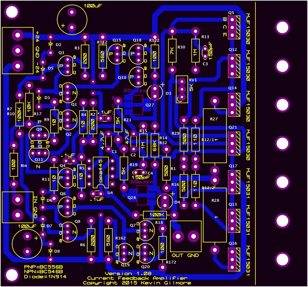
Marked up a board gerber with the part designations as best as I could from the CFA2 schematic.
-
The power supply looks like it could be a goldenreference clone? Different layout, and nice touch with the chips as you noted. Makes me long for the beautiful beautiful music!
-
and now for something completely different part 3
Pars replied to kevin gilmore's topic in Do It Yourself
I could be wrong, but I don't think that you combine the power draws of each rail? I think Amb explained it once that the draw is actually rail to rail and not each rail to ground. As I said, I could be misremembering this [emoji4] Sent from my iPhone using Tapatalk -
Sorry Carl, and RIP Enigma Sent from my iPhone using Tapatalk
-
You need the MPSW for the outputs, which is 8 per board. The MPSA will work for the others. Do the SMD version.
-
and now for something completely different part 3
Pars replied to kevin gilmore's topic in Do It Yourself
Team Single Chassis FTW! Nice job Michael! -
Even H2 headphones with personalized ‘Earprint’ signature
Pars replied to jvlgato's topic in Headphones
Hope this works out for you John! Fingers crossed... -
and now for something completely different part 3
Pars replied to kevin gilmore's topic in Do It Yourself
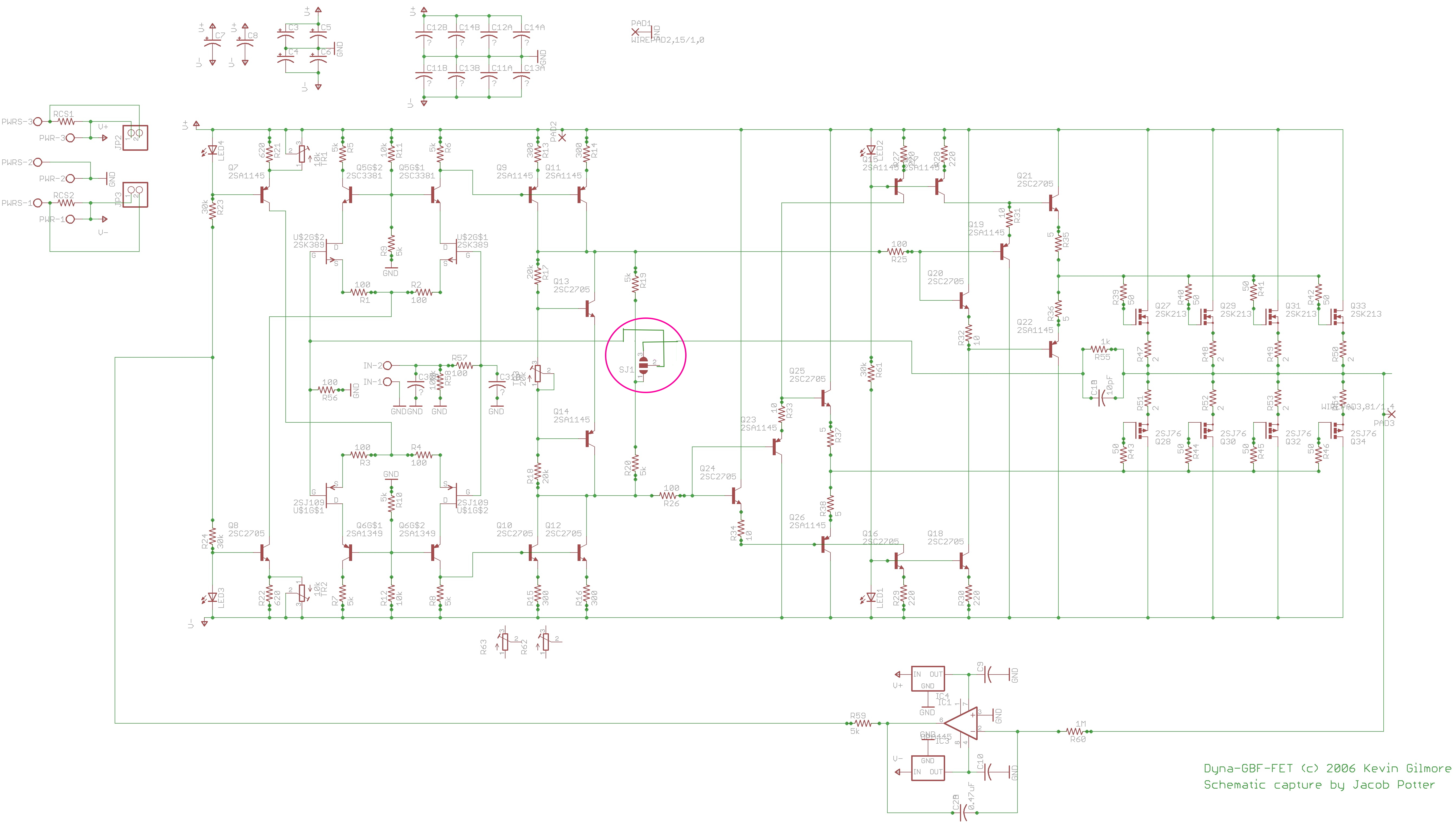
Is there any benefit to doing any parts matching on this? From looking at the schematic, maybe Q9/Q11, Q3/Q8, Q1/Q2/Q4/Q6, Q10/Q7, and Q27/Q28 look like potential candidates? I know mwl168 didn't do any matching on his with no ill effects. Sent from my iPhone using Tapatalk -
Good idea... no need chasing problems you don't actually have, though good to think about things such as this in advance. Sent from my iPhone using Tapatalk
-
Pretty low expectations for $4K, eh? And no, the product doesn't look very good. "Flimsy piece of shit" isn't an impression that I would associate with a good product. Sent from my iPhone using Tapatalk
-
Kevin had indicated to me that he hadn't done an SS DynaFet layout, and parts would need to be spec'd for it. I personally don't think i have an interest in building one. In a post I made around 5/27, I had put 3 links to diyaudio threads with some currently available mosfets that could be candidates. Back 1 page in the thread. 1) Semelab BUZ900 series (BUZ901P/BUZ906P) Sent from my iPhone using Tapatalk
-
Congrats Jacob and also more background? Best wishes to both of you! And yay Steve! Sent from my iPhone using Tapatalk
-
Thanks Kevin! Duh on my part but I hadn't thought the gain loop architecture thru on the mid point properly. This could explain why it was very unstable the last time I tried it, with an effective gain of 2 (I think?) with 1K and 1K for R56 . Earlier in the thread you had described the FB as multiloop (2nd paragraph of quote) and connected to both feedback points, which seems different from how this was actually implemented (1st paragraph). Not that I want to mess with mine anymore Sent from my iPhone using Tapatalk
-
Yes, I know the matched pairs item is 2 matched pairs (2xJ74 & 2xK170). I thought you meant that the 8xJ74 or K170 had 2 matched pairs in it. Sent from my iPhone using Tapatalk
-
I didn't see anything about anything matched. And note that the price that penmarker quoted is for A grade (Idss of 2.5-6.mA). B grade (6-12mA) is probably what most of us would be interested in. The price for those in the K170 is $32.76. The B grade J74s are $65 something (and out of stock).
-
Well, yes high. How many would you need to buy to ensure good matches if you were doing it yourself? ~$30 for 8 LSK170s and $62 for 8 LSJ74s. You might get a matched quad out of that, but I had heard that Linear's devices are all over the map regarding Idss within a certain grade.
-
After re-reading much of this thread (for I don't recall how many times), the feedback isn'w quite what I expected. It appears by the attached drawing, marked up to correspond to Kevin's post, that the feedback is either: pins 3-2: output to inverting input pins 1-2: midpoint of R19/R20 (2K, not 5K) to inverting input For some reason, I thought it was either 1 above, or output to midpoint. In looking the board files over, I see that that is wrong. Also, for the midpoint feedback (#2), there doesn't appear to be a gain resistor in play, unless R19 || R20 acts as the gain resistor? I'm using the output to input FB, and could not get the midpoint feedback even close to working. And to clarify on your comment on SJ2 (which was not on the boards), you had never intended to ground the midpoint of R19/R20 in any circumstance? Thanks!
-
Speaking of which, I thought that Linear had released an LSJ109? They don't show them on their site, and from what I could find, they claimed they were available, but no one seems to have gotten any? Fast forward to today with the LSJ689... Trendsetter doesn't list them, and apparently the other place referenced doesn't either? Are these going to be the same thing again? They do seem to really have LSJ74s, so at least there is that.