Leaderboard



Popular Content
Showing content with the highest reputation on 05/03/15 in all areas
-
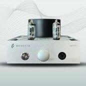
6 pointsThanks to the NYC Spring Meet yesterday, I was motivated to finish casing up my KGST. I'm very happy with the result. The chassis is 7" x 12.8". Perfect for my night table Here's the beast in it's intended home: Still need to do the finish and put a respectable knob on it. Here's the back of the amp. Because of the size I wanted to use a single 5 pin mini xlr. Had to build a cable as well. I Put the DAC behind the night table to keep a clean look. I'm just spent the last couple of hours listening and just love it.6 points
-
1 pointI've been the proud owner of a Cavalli Audio Liquid Lightning for over a month now. Now as most will know, this hasn't been exactly a dream of mine but the owner practically begged me to take it and the price was low enough to waste money on it. The normal market price on the Mk1 model has dropped well below half of retail (2400$) at this point and this one was even cheaper. What finally made me buy it is the very unhealthy discussion about this piece and the clear attempts of the manufacturer to kill any negative discussion about it. My views will be questioned because of my history with Cavalli but that's exactly what should be done to any impression that is read. Nothing should be taken as gospel but I've put my money where my mouth is and that's not something you can say about the people who rave about the LL. The main goal of this thread though will be to document just how badly built and designed this amp is but also to document ways of improving is and indeed, making it safe for the user. The circuit has been fully drawn up and analyzed and it will be posted in full later on. Any issues of copyright are blown aside as this is very similar to the Exstata which in it self was a Stax design lifted off the web. Cavalli has admitted to that in the past and the "improvements" make it even more similar to the SRM-323/727. We'll get to that later though when I start the ordeal of making something useful out of this box. Perhaps we should start with some impressions of the sound. First impressions were just how small it is and very light. It's about double the size of the SRM-727/007t but doesn't weigh all that much more. The casework is flimsy but well made. Some plainly odd bits such as the volume knob is painted, not powder coated as one would expect and there is no primer used. Very odd... The switch on the front is neat but the circuit driving it could use a lot of work. As for the sound, well the output capacitance of this amp is about 300pf so it sounds very odd. It's utterly unusable with the SR-003 as they are just 44pf with the cable. Same with the SR-007 and SR-Omega, way, way too much bass, no life at all and the treble is just gone. The midrange which makes these so special has no depth, no height so voices just sit flat on the front of your face. Let's break this down a bit: The bass is by far the worst part about this amp. There is no sub bass output and the rest is both anemic and overblown at the same time. The bass has no power, no heft until it hits a certain frequency range and then it turns into a overblown mess that consumes everything. This is worthy of cheap closed dynamics and is very annoying. The SR-007 when driven well rivals any transducer when it comes to bass impact but here it is just a weak muddling mess. The midrange doesn't have any presence or bite to it, it just sits there. The soundstage has no depth and is pretty much stuck directly in front of the face. Remember those bell graphs... that's how it sounds. Some output low down on each side but almost everything in the center. The HE90/Stax hybrid I have rivals even the Sigma's when it comes to casting a vast soundstage but here it is just dead. The lovely out of head experience of the SR-Omega... completely gone. Voices are separate and not really joined in with the rest of the stage, almost like a bubble directly in front of the eyes. Truly weird and it's there no matter the recording. The top end is highly rolled off, there are no shimmering cymbals here or guitars piercing as they are driven into overload. Nope, just lifeless and inoffensive. I can see people liking the SR-009 with this but it's like taking a sledgehammer to the sound. Instead of gently molding the top end it's just cut off entirely. Now this is the Liquid Lightning Mk1 I have here so how different is it to the Mk2? Well until I posted my findings it was supposed to be identical on the inside, all the same parts used and just some slight tweaking plus the new case. Now suddenly it is massively different and a gigantic improvement. Nothing backs this up, no pictures, no clearly defined part changes and only the testimony of people to who I wouldn't take at their word. Until something comes along that actually backs up these stories of major improvements then I have to assume that they are exactly the same. Same output devices which have a combined output capacitance of 270pf per transducer and the same fucked CCS that kills the top end and fucks up the phasing on the low end. Finally the first steps in improving this pile of fail. I naturally needed to change it to 230V so I was greeted by this: That is not a very professional job to be honest. Two wires are the primary windings of the small standby transformer and the two green wires are the pass through to the large HV transformer. Here is how I did it. Fun fact, there is actually no locknut on that grounding post. There are two lock washers but they are both right next to the eyelet, there is none on the nut which secures the whole assembly. You can see where this is going, fucking amateur hour... To cap this off I decided the blue knob had to go. This is what I had "in stock": Much better and since that is a Headamp knob I hoped that the amp would sound a bit better. It didn't...1 point
-
1 pointmake sure you use 500v caps, and it will work at 400v. obviously change the zener string and transformer. in other news, kgsshvcarbon boards by joamat posted. mirror images for the truly insane.1 point
-
Let me get back to something I discussed briefly in my first post but haven’t addressed since then, and that is that stat headphones must consume power because they produce sound. Now, all the calculations I’ve done up to now are based on a simple model of the electrostatic headphone as a capacitor. However, even though capacitors use require current from the amplifier to swing voltage, they don’t use up power because the voltage and current are out of phase. And of course, we don’t listen to capacitors because they don’t make a sound (at least in theory). Since headphones do make sound, that means they must use extra current from the amplifier beyond what we have previously calculated. So let’s take our previous example of 800 volts peak-to-peak. This is 400 volts peak, and since Dr. Gilmore has stated that the SR007 can consume one watt at peak output, let’s say the peak current is 2.5 mA, which works out to that one watt peak. If we add this current demand to our previous results, we get: ESX 50k load resistors: 10.6 mA = 66% of 16 mA standing current ESX 10M90S current source: 5.1 mA = 32% of 16 mA standing current = 18% of 28 mA standing current (T2) = 14% of 36 mA standing current (BHSE) SRX Plus cascode current source: 2.9 mA < 14% of 14 mA standing current Again, these are “back of the envelope” calculations so don’t take the absolute numbers too seriously but the relative relationships should hold good. We can now see why pongo5's Egmont sounds much better with constant current source loads. The Egmont with 60k load resistors is similar to the ESX with load resistors in terms of current demand, whereas the Egmont with cascode current sources is similar to the SRX Plus. The basic circuit draws 3x as much signal current for the same signal voltage because the load resistors waste so much of it swinging the voltage in the resistor.1 point
-
1 point
-
1 pointIs that a Fred steak and did you forget to take a picture after cooking again?1 point
-
1 point
-
1 pointAnother super cute movie is "History of Future Folk". About aliens who come to earth to destroy it, but hear music for the first time and fall in love with it, and start a bluegrass duo instead. Just insanely adorable from beginning to end.1 point
-
1 point
-
1 pointBought a ticket to go to my first movie in a theater in I would guess around 15-20 years. I figure one every couple of decades is a good average. Theaters seem to have much better beer lists now than the last time I went to the theater. https://d994l96tlvogv.cloudfront.net/uploads/cafe/menu/afcmosaic-menu-lounge.pdf1 point
-
Thanks for the comment, Dr. Gilmore, that's a very good point. One thing about the cascode CCS (constant current source) on my SRX Plus (modded SRX) is the output voltage drifts about 40-50 volts as it warms up, also the final value may vary by a few volts with different turn-on/turn-off cycles, presumably due to thermal issues. Thermal stability is very significant for practical amplifiers. In terms of the LL, my copy of the prototype schematic courtesy of Dewey, Cheatem and Howe , uses the same topology as figure 3A discussed in my previous post, but substitutes a MOSFET for a BJT as the device that has the large voltage swings in the output CCS. Here is what Jung has to say a few paragraphs earlier in his introductory remarks in the section discussing the one VBE current source shown in figure 3A: "Of course, higher-voltage parts should be used when appropriate. While exotic and super-high-gain parts aren't necessary for very good performance from these circuits, LOW CAPACITANCE DEVICES DEFINITELY ARE PREFERRED (<10pf), A CRITICAL POINT IF SUBSTITUTING [emphasis added]." The reason is that high capacitance devices cause the effective impedance to decrease at high frequencies, degrading the performance of the current source. Given that MOSFETs have a relatively high shunt capacitance, this means that performance of the LL output current source is likely to be even worse than the BJT version that Jung cited as a design to avoid. Now the "fixed" version of the LL uses a low-capacitance BJT for the MOSFET, which is better, but.... the SRM323, which shares a very similar topology, uses the LED and BJT CCS on the output, which is significantly better than the CCS of the "fixed LL." You can't say that Dr. Gilmore and spritzer didn't warn us about this when the LL came out, although they didn't go into it in the infinite gory detail that I just did. Now, one of the advantages of a cascode MOSFET CCS such as the SRX Plus uses, is that the upper device shields the lower device from voltage variations, so that the lower device, which sets the current, sees nearly constant voltage regardless of the voltage variations across the cascode pair. This means that the effective capacitance of the cascode is very low, so its performance is preserved to high frequencies. For example, Pimm measured a cascode DN2540 pair as having an effective capacitance of < 0.2 pf! By comparison a single DN2540 measured about 32 pf. ADDENDUM: I got a look at the production schematic courtesy of spritzer's LL Mk I thread elsewhere on this site. The output current source is identical to the Dewey, Cheatem and Howe version with the exception of a protection zener added to the MOSFET in the production version, so same lousy performance.1 point
-
I've been binging on Archive live concerts on YouTube, I think they've surpassed Anathema as my favourite of "that" kind of music, whatever "that" is. Example: Right now taking a detour for a London Grammar concert:1 point