

Leaderboard
-
swt61
High Rollers15Points22272Posts -
VPI
High Rollers12Points9103Posts -
Hopstretch
High Rollers10Points16809Posts -
Grahame
High Rollers8Points16831Posts



Popular Content
Showing content with the highest reputation on 04/21/18 in Posts
-
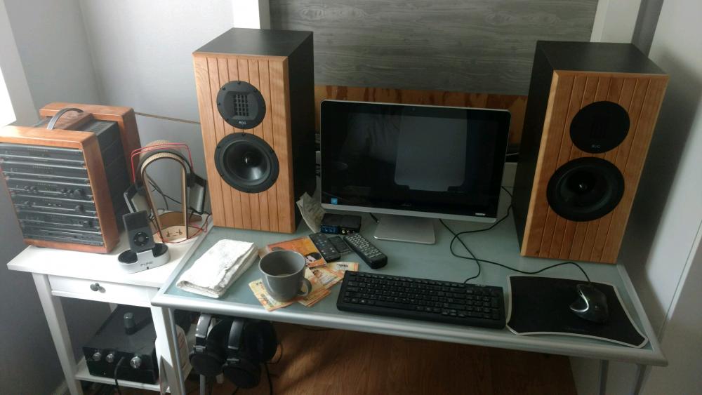
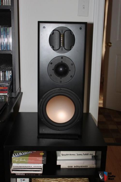
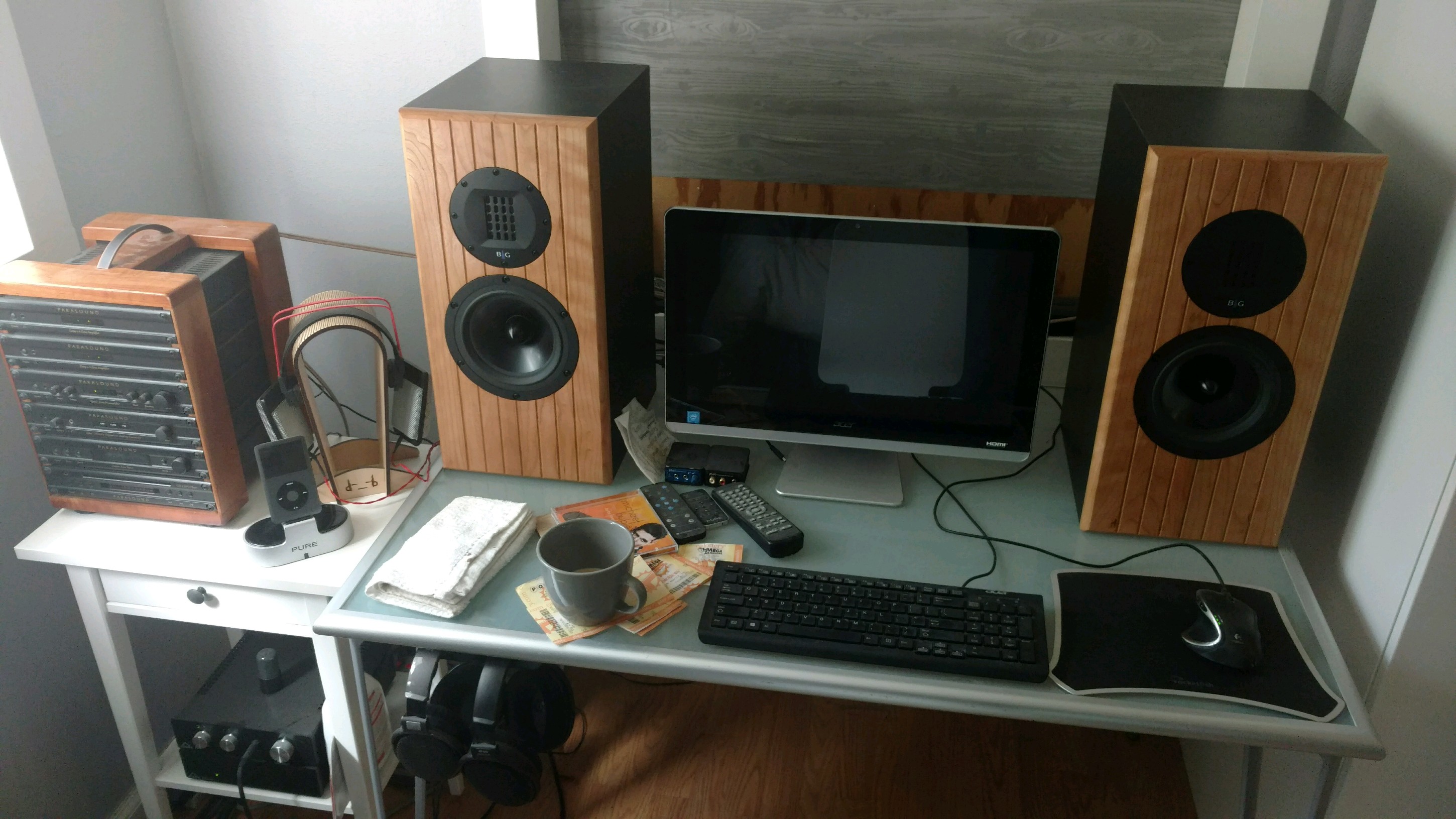
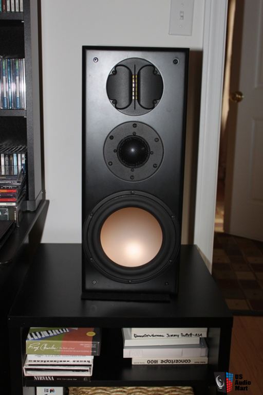
8 pointsDone! These are not just your standard two ways. Instead, Marc has paired basically a full range driver and a super tweeter, then customized a crossover to take best advantage of that pairing. These drivers have to stretch their legs before I can really assess them, but so far I'm impressed. They're bigger than I had originally thought I'd build them, but still, make a pretty good nearfield monitor. Bass is far better than I expected. Eventually, they will darken to match the Parasound case. The window will speed that process up.
 8 points
 -
4 points
-
3 pointsThat burger was too fucking much. This morning having something slightly lighter, the Cowboy Egg Casserole at Citizen. Sent from my iPhone using Tapatalk3 points
-
3 pointsUltra Burger at Quinn's Pub. Duck egg, wild boar sloppy joe inside an onion ring, topping bacon, white cheddar, and an 8oz Pattie on a nice bun. Too bad they took med rare as "burn the shit out of it." Sent from my ONEPLUS A3000 using Tapatalk3 points
-
2 points
-
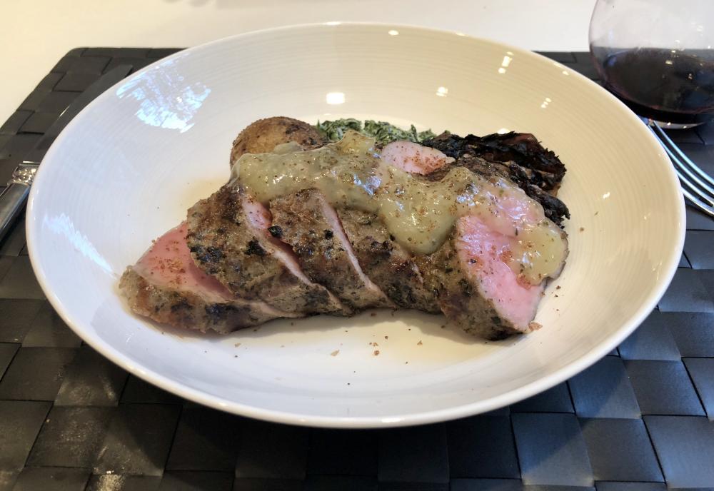
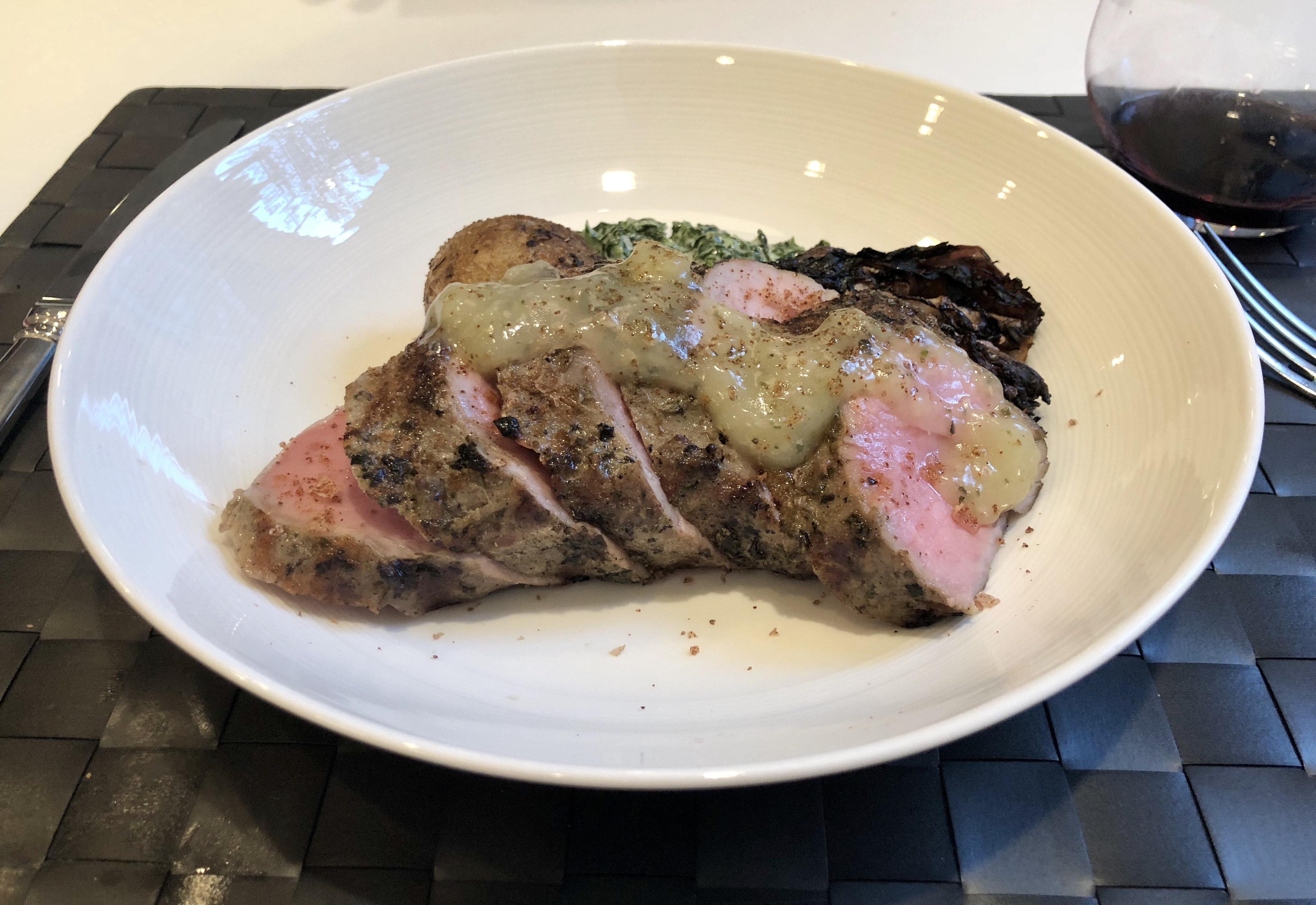
2 points2 pointsHeisenberg, Schrodinger, and Ohm are in a car. They get pulled over. Heisenberg is driving and the cop asks him "Do you know how fast you were going?" "No, but I know exactly where I am" Heisenberg replies. The cop says "You were doing 55 in a 35." Heisenberg throws up his hands and shouts "Great! Now I'm lost!" The cop thinks this is suspicious and orders him to pop open the trunk. He checks it out and says "Do you know you have a dead cat back here?" "We do now, asshole!" shouts Schrodinger. The cop moves to arrest them. Ohm resists.2 points2 pointsLemon oregano sous vide pork loin with cumin baked potato, creamed spinach and balsamic-grilled radicchio.
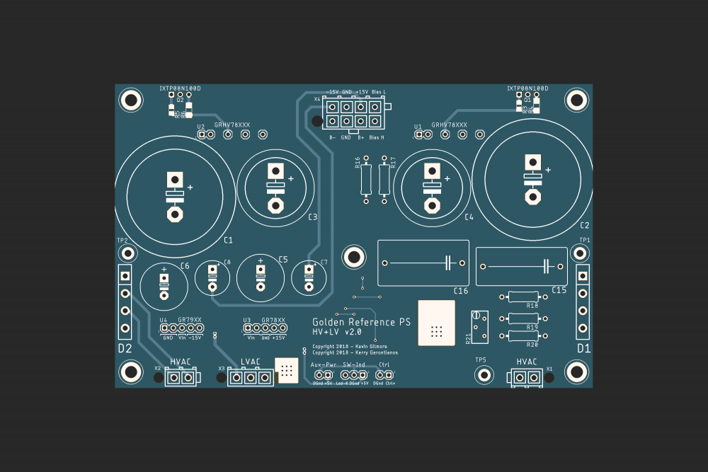
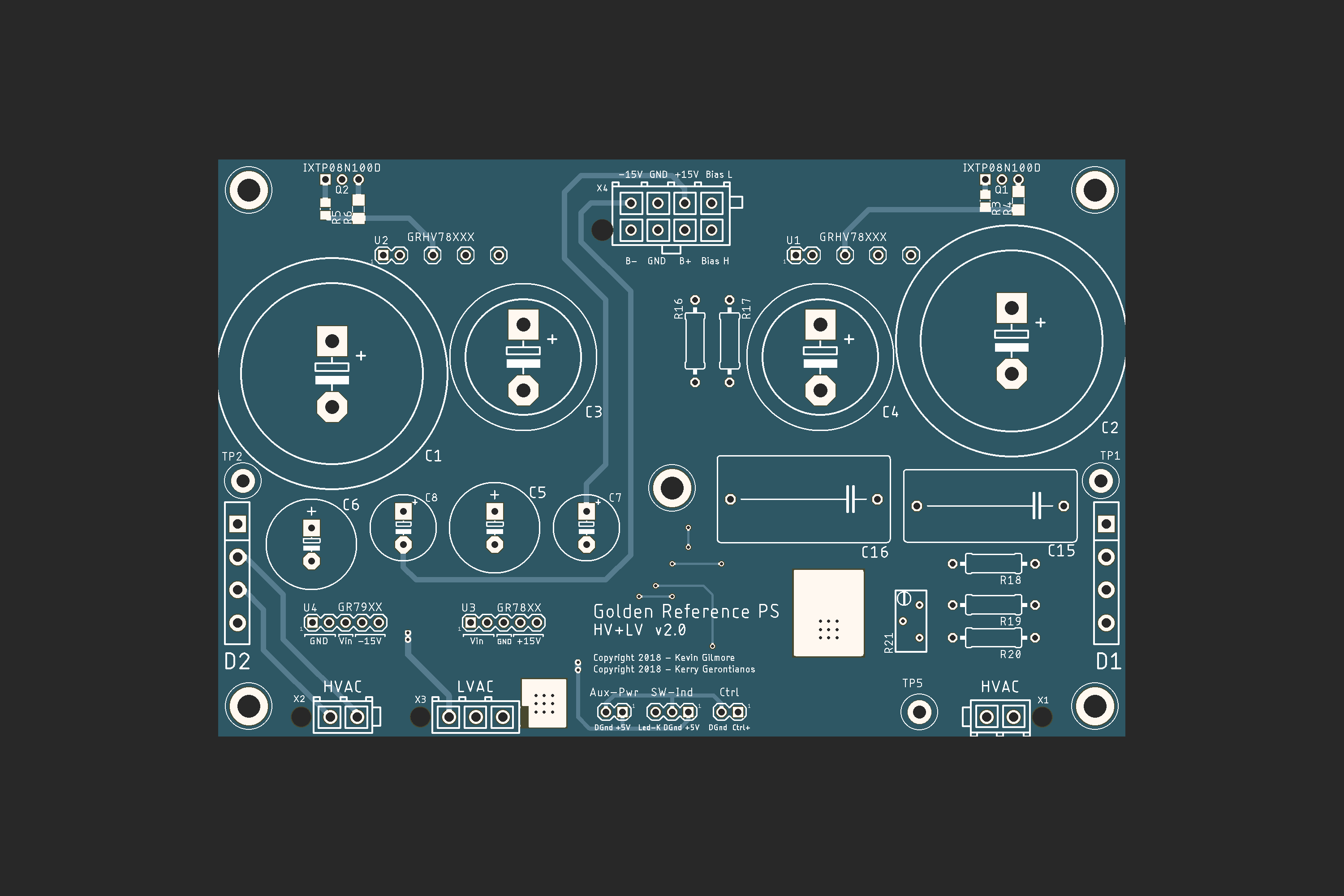
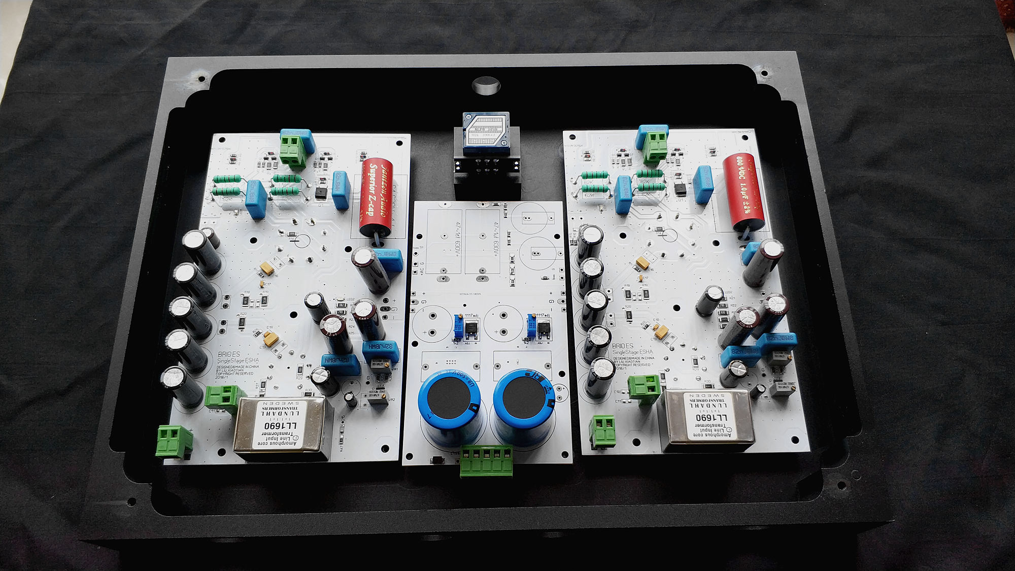
 2 pointsHere's the accompanying board for the GR HV & LV supplies. It's got a built-in controller to turn the HV on after a delay (if needed) along with a power LED indicator (flashing to solid). I've also added a tap for both Normal and Pro bias.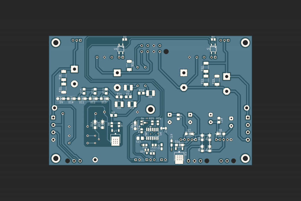
 1 point1 point1 pointAcoustic guitar is wonderful. Haven't really rocked out yet, still loving Alison Krauss and Adele ATM. Hey, I'm gay, what'd you expect?1 point1 pointThis time I won't be an early adopter. Maybe not even a later one, hopefully not a late one.1 point1 pointHoly fuck!!! I'm just so thankful they don't serve that on a biscuit! Otherwise, the entire West Coast would sink into the sea!1 point1 pointLitz cables for electrostatics are all kinds of stupid so Stax would never do that. Nice gold plated stators and hopefully they fix the bloody voicing.1 point1 pointOh shit, it looks like Jeff, Colin and Brent are out on the town ...
 1 point1 point"This top model of open-ended electrostatic headphones is a challenge for the most demanding audiophiles, requiring uncompromising sound reproduction quality across the 5 Hz to 42 kHz frequency band. Thanks to the new generation of thinned Electrode Electrode (MLER2) Electrode Membranes (MLER2), the new geometry of air reduction holes and its gilded surface, which with its high specific gravity even further suppresses unwanted vibrations, brings the headphones perfectly balanced reproduction even in the area of the deepest frequencies. All-metal aluminum earbuds basically eliminate undesirable resonances. Headphones are designed exclusively for connection to any STAX desktop power amplifier." Additional information: http://www.audiotuning.com/images/Stax/Stax-SR-009S-Pi-UVP-170418.pdf
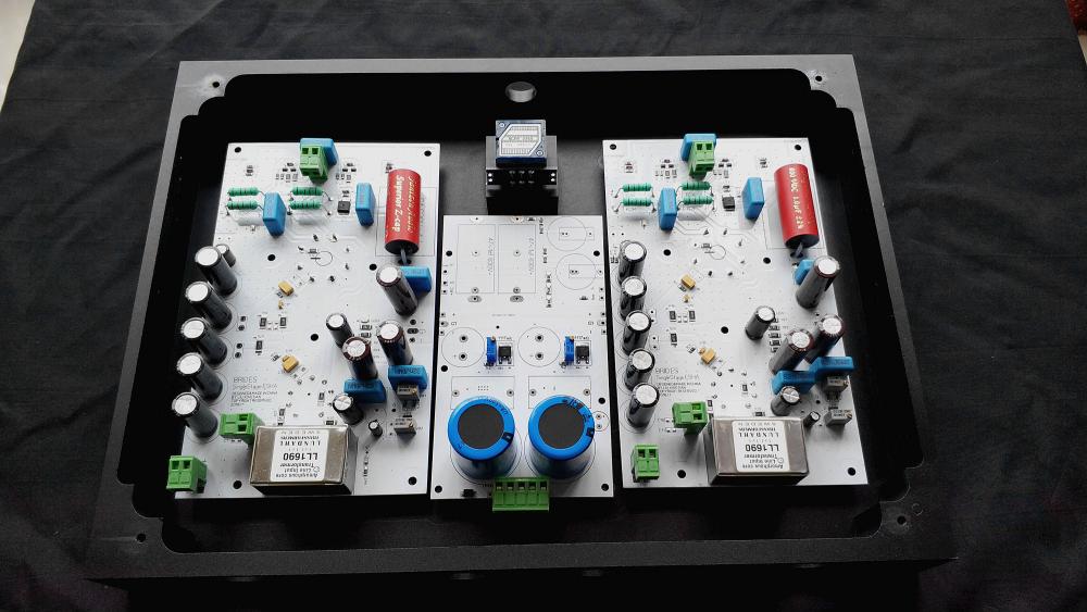
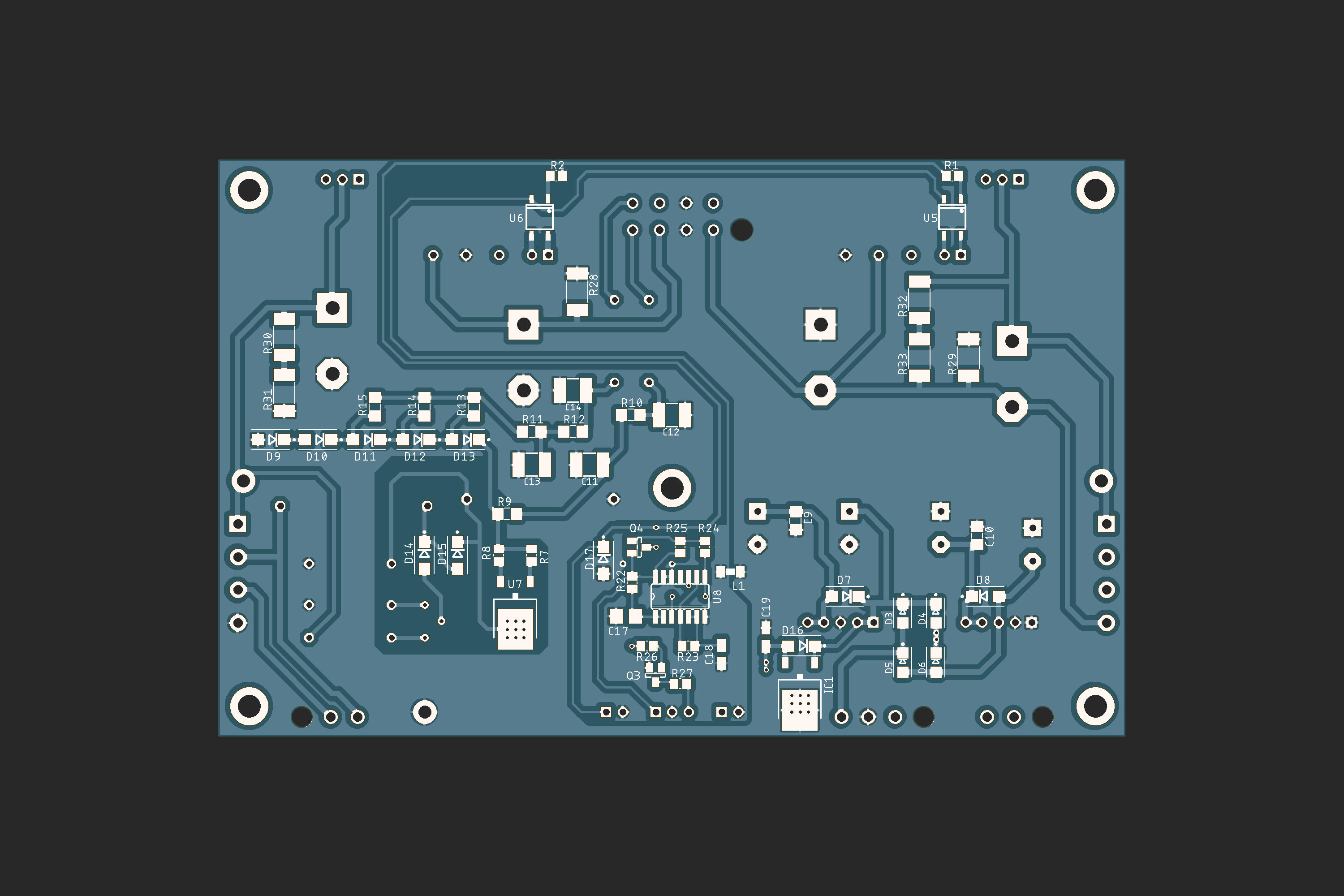
 1 pointTest Tone @ Home live right now: http://mixlr.com/illuminator/chat1 point1 pointThis is a detailed(relatively) schematic of the latest version. The transformer should be a 1:1 input transformer with proper insulation(1000V or more), and a Faraday shield which is connected to ground plane. the plate load resistors are 2 or 3 watt 62k resistors. The power supply ripple rejection(PSRR) of resistor load is low compared to a constant current source load, so I added an active de-coupling circuit using only one enhancement MOSFET, and a few resistors and a capacitor, which significantly reduce power supply noise seen by the 4 62k resistors. -360V and -420V voltage reference is simply generated by a series of resistors forming a voltage devider, which is not shown here. the 100R variable resistor connected to the cathodes of ECC88 is bypassed using a 1000uf bipolar capacitor paralleled by a 22uf smaller bipoalar capacitor, in order to achieve a higher gain and 'higher distortion' or you can say a more 'tuby sound' , you can cancel these bipolar caps if you prefer lower distortion and a clearer sound . the tail CCS of ECC88 is a CCS using DN3135, not DN2540 which is a common STAX mafia choice. The capacitance of DN3135 is lower than DN2540. Some of you might have noticed that, in this amplifier, the dual-unit RK27 potentiometer doesn't seem to be andequate to control the volume of balanced audio signal. In fact, the volume control circuit here in this amp is different from how we normally use potentiometers---- it's a parallel connection instead of serial connection, the audio signal flows through the 6k8 resistors, and then, directly flows into the grids of ECC88, potentiometer is connected in parallel with ECC88's grids. This volume control circuit will deliver more transparent sound as audio signal does not flow thru the dirty and noisy carbon-film RK27 potentiometer first, then into the amp. Another thing concerning safety operation is that, since the center tap of the transformer is connected to approximately -420V, the variable resistors inside an RK27 are biased to -420V too, we DO NEED TO consider if the potentiometer can withstand such high voltage between the internal components and its housing. Luckily, Alps RK27 and RK16 have an electric insulation of >500Vrms as shown on data sheets, so -420V is safe enough. The input signal impedance of a signal transformer is usually suggested to be as low as possible. I used to connect a potentiometer before signal goes into input transformer, trying to avoid high voltage insulation issues, but as a result, the bass is massively degraded due to increased distortion when the transformer is fed by a high-impedance signal. And here are pictures showing my PCB design. The components on this PCB are mostly SMT parts, except large capacitors, and tubes. Please note that the output MOSFETs and their CCS loads are TO-252 IXTY01N100D, the heat becomes an issue in this situation. I experimented 8mA current, and the heat was OK, as the MOSFETs are heavily pressed onto the bottom of an aluminum chassis through a 0.5mm or 1mm silicon rubber pad. For a better reliability, I limit the current to around 5mA(a bit more than 2 watt heat per MOSFET), which is enough current to drive(although not perfectly drive) a STAX headphone. If you want MORE current, you can try to-220 package. top layer(cyan) bottom layer(grey)
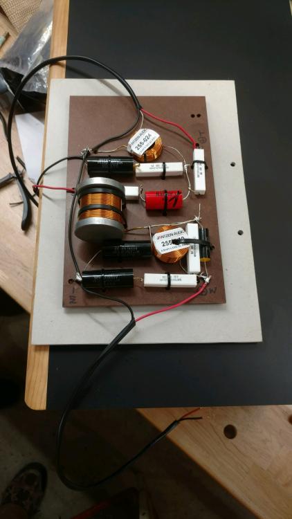
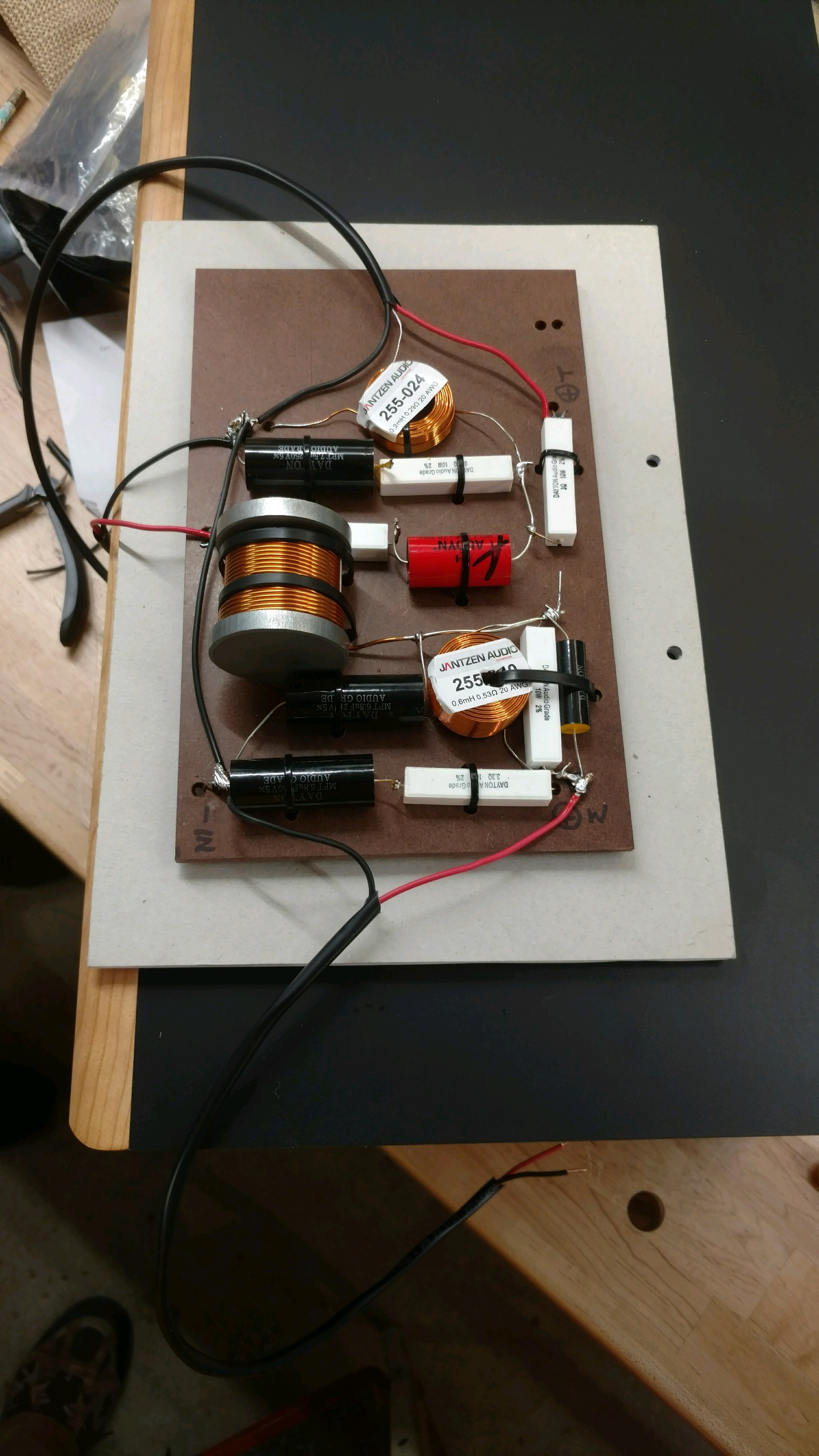
 1 point1 pointMe: Barked clams and house made spinach linguine aglio y olio. Anne: Portobello stuffed gnochi1 point1 point1 pointI had a pair of these... And a 50" Panny Plasma in a small class C motorhome. This will be a walk in the park. We got one crossover finished, will most likely finish the other Tuesday eve. I'll glue on the Cherry baffles tonight, then it's just a matter of soldering on a few spade lugs.
 1 pointI acquired 10 boxes of my friends' record collection that I helped amass and listened to daily during high school. Picked a 12" Echo and the Bunnymen for sentimental value and then something else I haven't heard in years. Fun stuff.
 1 pointhttps://www.usatoday.com/story/tech/2018/04/20/smugmug-buys-flickr-verizon-oath/537377002/ Fuck me with a 300mm F/2.80 points















Important Information
By using this site, you agree to our Terms of Use.