

Leaderboard


Popular Content
Showing content with the highest reputation on 03/26/20 in Posts
-
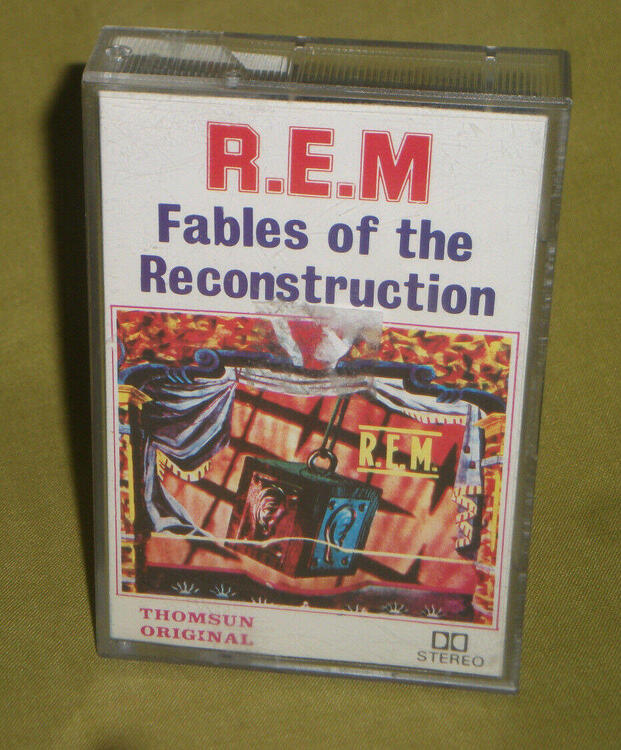
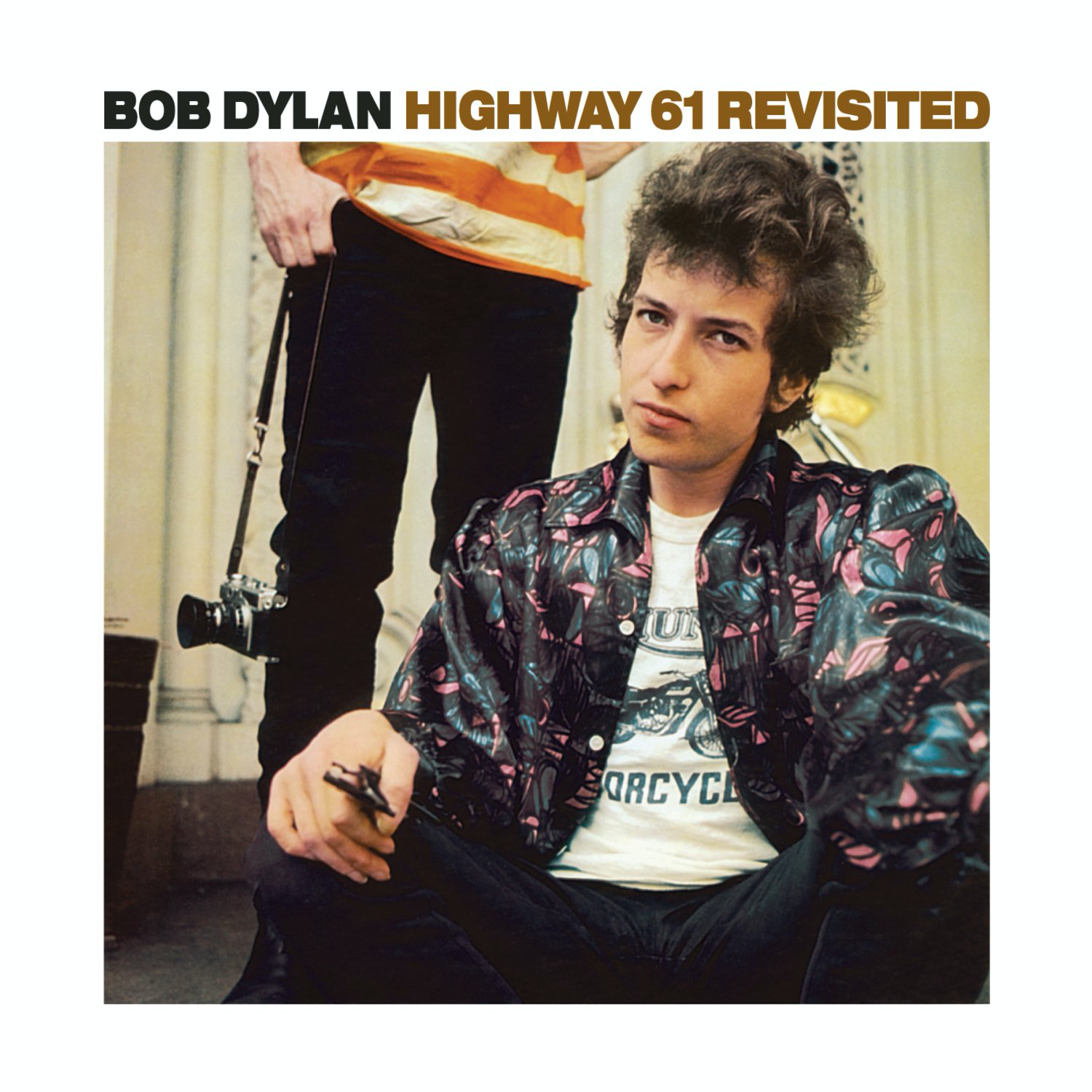
7 points6 pointsMaybe this makes me not a real R.E.M. fan, but I think this is their best album. By a wide margin.4 points3 points2 points2 points2 points^^^ This one still wins... and thanks to youtube...2 pointsIMO one of the very best albums of the last decade. Arcade Fire - The Suburbs2 points2 pointsI am moving Kerry's mini GRHV\GRLV GB discussion to its dedicated thread here. I also included JoaMat's mini T2 here to see if we have enough interest for a GB. The table will be updated periodically as more people participate. Apologize if I missed someone or something - just let me know so I can correct the data. I put down one set for those that have not decided on the number of sets they want. The plan is to have assembled GRHVxxx boards, rest of boards will be PCB only. See discussions on the PS in this thread. mini T2 build discussion in this thread. Construction notes: R3 and R2 determine the regulated voltage for GRLV. The formula is Vout = (R2 + R3)/R3 * Vref. Vref is the reference voltage of U4 (LT1021). R7, R8, R9, R10 determine the regulated voltage for GRHV. The formula is Vout = ((R8 +R9 + R10)/R7 + 1) * Vref. Vref is the reference voltage of IC1 (LT1021). You want to keep R8, R9 R10 values close so they have even voltage drop across each of them. On the PSU Main board, R22 (100K) and C17 (470uf) set up the delay time for HV. The 100k/470uf combination provides a roughly 45 seconds delay. Increase R22 or C17 to increase the delay time. C17 needs to be rated 5VDC or higher. Board dimensions: mini T2: 160mm x 100mm GRHVxxx: 41mm x 31mm GR78xx/GR79xx: 30mm x 20mm Main board (PSU): 140mm x 90mm See BOM for boards at the bottom. Blank in the GRHVxxx-bare column indicates that the participant has not responded on this thread to indicate the preference for bare or partially-assembled boards and is deemed to opt for partially-assembled board by default as previously communicated. BOM: GRHV78xxx-BOM.xlsx miniT2v.22_Date_2020-02-16.xls GR78xx - V2 .xlsx GRHVBase-BOM - V2 production.xlsx GR79xx-V2.xlsx1 point1 pointI’m building a Controleo3 based re-flow oven for the SMD soldering until I get more experience on test boards with hand soldering SMD components. It should leave both hands free😊. Just waiting on the toaster oven to arrive on Saturday to start modifying it.1 pointI think Document and Life's Rich,.. were my favorites until I went to their 1995 concert. Then Monster took the lead (naturally).1 pointFables of the Reconstruction is the best!* *REM considers it their worst.
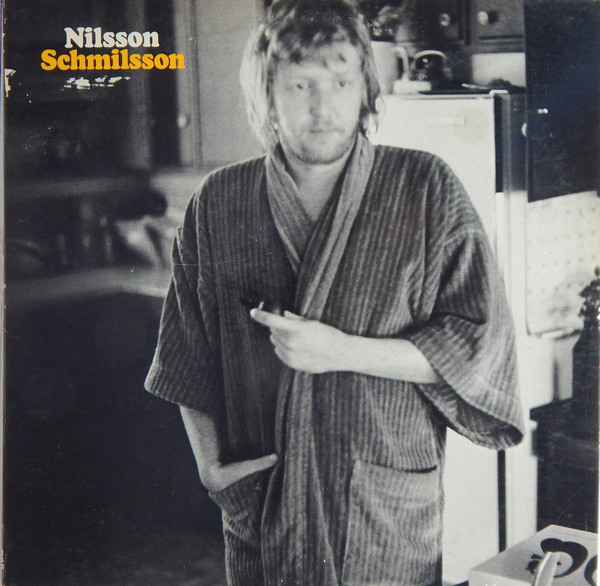
 1 pointMy fave REM albums go back even further.....! Maybe Reckoning.....though "Fall On Me" from Life's Rich pageant is one of my all-time favorites.1 point1 pointI did exactly that - built a universal PSU for KGSSHV, Carbon, GG, BH and the CFA. IME, GG and BH are rather similar. Have not heard a full DIY T2 but building one PSU, a BH and a Carbon will not come close to what it costs to build a T2.1 point1 pointme think that God would have given us three hands if we were meant to do SMD soldering.1 point1 pointtomislavkufrin There is the mini t2, if you dont mind surface mount for the amp boards, you can use exactly the same golden reference lv supply as the blue hawaii - zero changes, the same golden reference hv supply with two resistors changed to go from -400V to the mini t2 -460V, add another golden ref power supply for the +220V or a dropped resistor from the +400V to save an extra power supply board and transformer winding.. if you use two transformers - one to supply the heaters and the plus and minius 15V DC - that transformer can also be used on the blue hawaii the second transformer can supply the voltages for the 220V, -460V and +400V. I think the sound of the mini t2 is better than the blue hawaii (a big enough difference that my mini T2 is now my daily stax amp and the mini t2 runs cooler) and quite a lot of the mini t2 can be re purposed if you do decide to build a blue hawaii some time. The blue hawaii is also a nice amp if you dont want to do smd soldering. personally Im waiting for someone to design a reliable full diy t2 using modern components.... Kevin? JoaMat?1 point1 pointTable updated. Construction notes for those getting started to source parts for your builds: R3 and R2 determine the regulated voltage for GRLV. The formula is Vout = (R2 + R3)/R3 * Vref. Vref is the reference voltage of U4 (LT1021). R7, R8, R9, R10 determine the regulated voltage for GRHV. The formula is Vout = ((R8 +R9 + R10)/R7 + 1) * Vref. Vref is the reference voltage of IC1 (LT1021). You want to keep R8, R9 R10 values close so they have even voltage drop across each of them. On the PSU Main board, R22 (100K) and C17 (470uf) set up the delay time for HV. The 100k/470uf combination provides a roughly 45 seconds delay. Increase R22 or C17 to increase the delay time. C17 needs to be rated 5VDC or higher. Also added these construction notes in the first post for ease of access.1 point1 point1 pointThe Great Empty: Photographs by The New York Times
 1 point


.JPG.c82f4b3383b4c5b1515f0f9a906f24b1.JPG)


Important Information
By using this site, you agree to our Terms of Use.
Account
Navigation
Search
Configure browser push notifications
Chrome (Android)
- Tap the lock icon next to the address bar.
- Tap Permissions → Notifications.
- Adjust your preference.
Chrome (Desktop)
- Click the padlock icon in the address bar.
- Select Site settings.
- Find Notifications and adjust your preference.
Safari (iOS 16.4+)
- Ensure the site is installed via Add to Home Screen.
- Open Settings App → Notifications.
- Find your app name and adjust your preference.
Safari (macOS)
- Go to Safari → Preferences.
- Click the Websites tab.
- Select Notifications in the sidebar.
- Find this website and adjust your preference.
Edge (Android)
- Tap the lock icon next to the address bar.
- Tap Permissions.
- Find Notifications and adjust your preference.
Edge (Desktop)
- Click the padlock icon in the address bar.
- Click Permissions for this site.
- Find Notifications and adjust your preference.
Firefox (Android)
- Go to Settings → Site permissions.
- Tap Notifications.
- Find this site in the list and adjust your preference.
Firefox (Desktop)
- Open Firefox Settings.
- Search for Notifications.
- Find this site in the list and adjust your preference.