

Leaderboard

Popular Content
Showing content with the highest reputation on 02/14/22 in all areas
-
2 points@mikeymad https://www.theguardian.com/film/2022/feb/14/ivan-reitman-hollywood-hero-ghostbusters-director-hadley-freeman2 points
-
2 pointsDiscovery of the day. The $1 special, Lg. sugar free iced coffee from McDonald's becomes a premium drink with the addition of Kirkland Irish Cream. (If maybe not so sugar free anymore)2 points
-
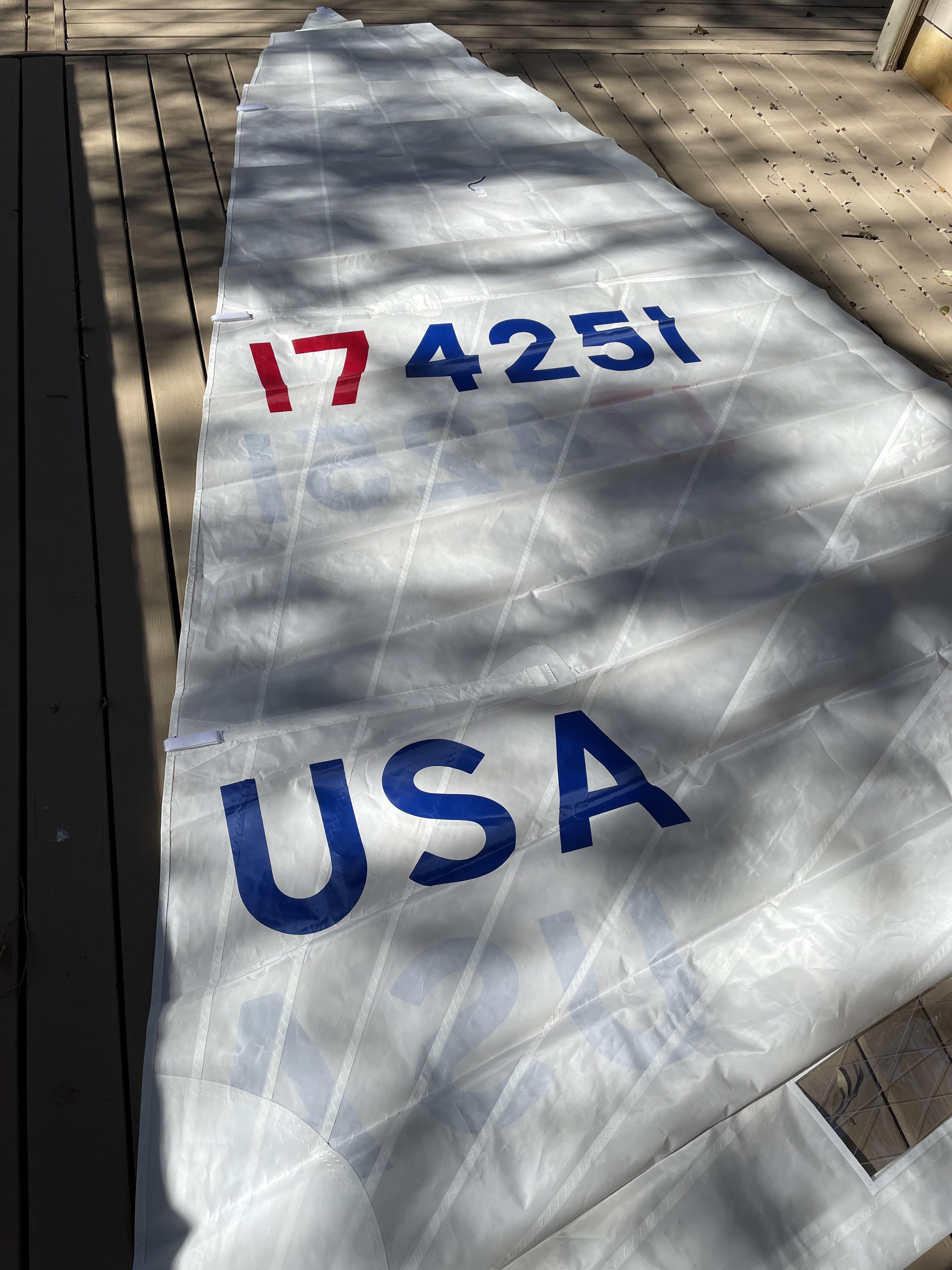
2 points1 point1 pointShould be able to call a local cabinet hardware supplier and pick up some imports. Normally you will want the slide, the front adjusters, and the rear mounting bracket.1 point1 pointApplied new numbers to a brand new sail! A bit tedious but turned out ok I think.
 1 point1 pointJoanne suggested a Baileys / Kirkland Irish Cream taste test (for science!) Earl grey / Mickey D's "Coffee" optional.1 point1 point1 point1 point1 pointWhat a difference a week makes. Today it was 55F and most of the snow is gone, so switched vehicles.
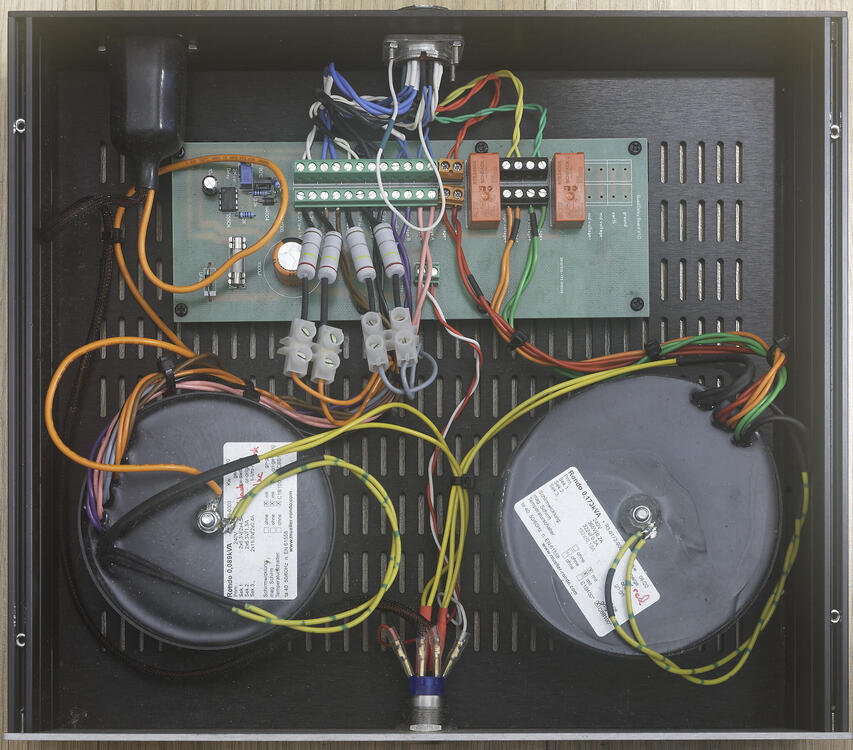
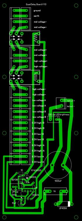
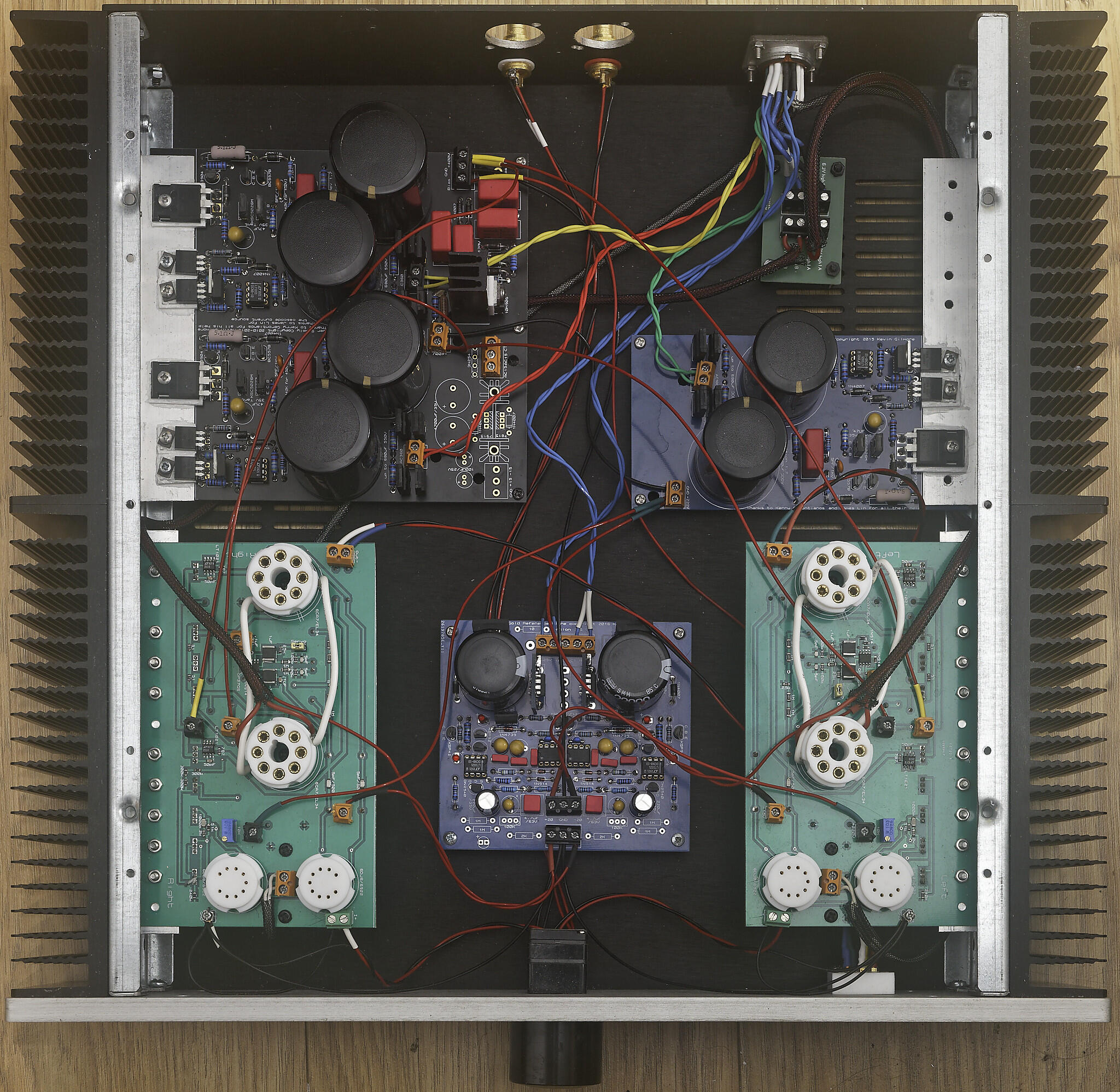
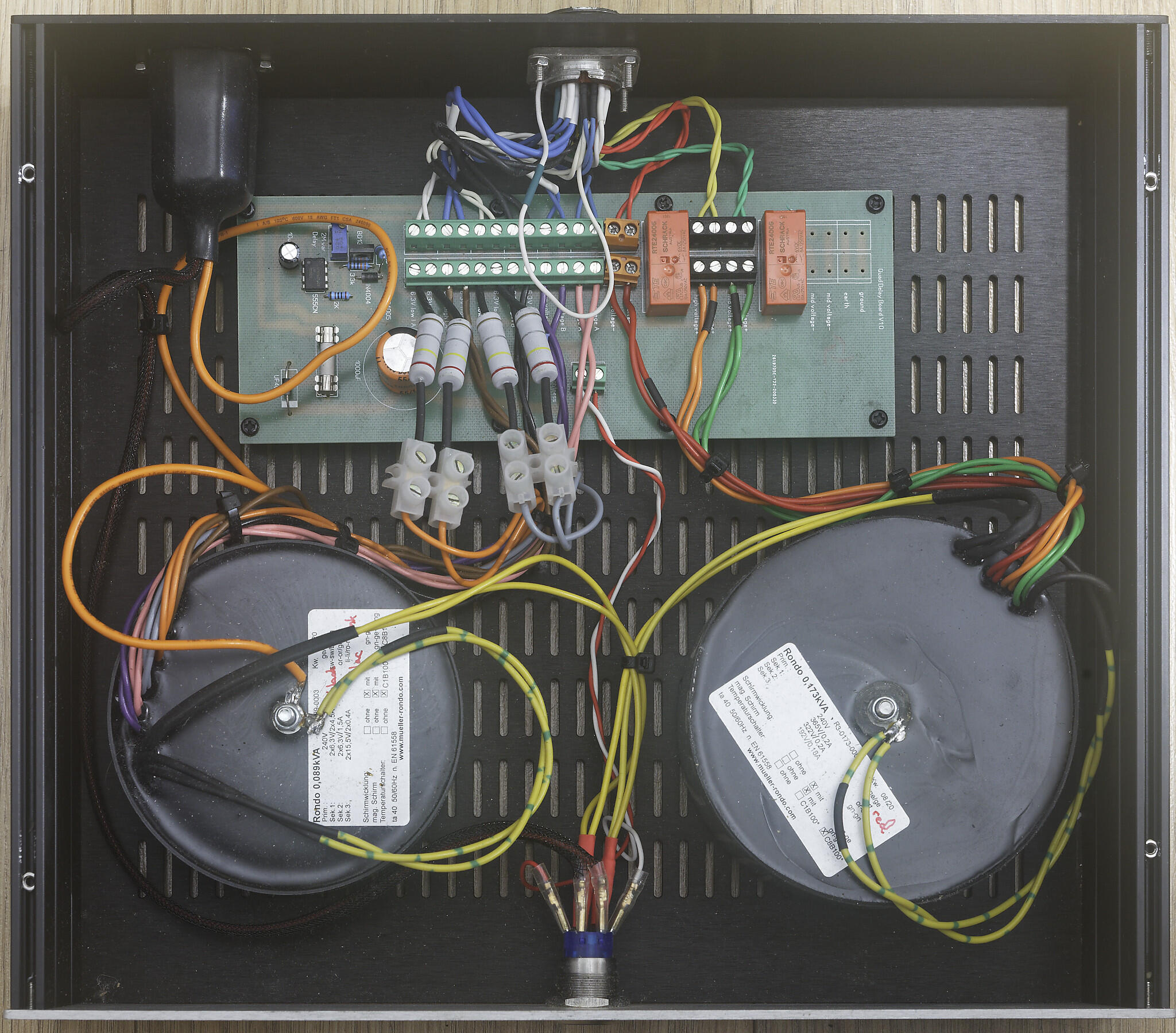
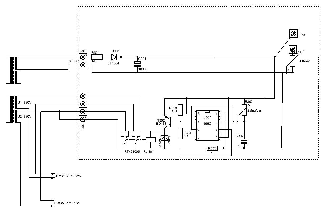
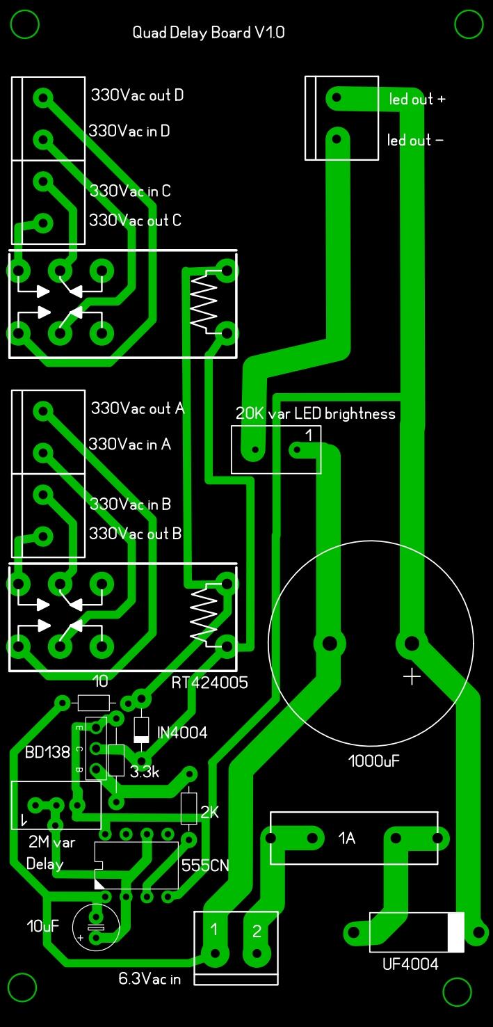
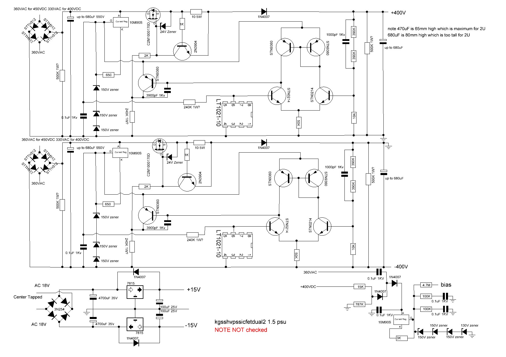
 1 point1 pointthere are many possibilities: for the power supplies first you need to decide if you want to heat the valves up before you apply high voltage. If you do then there are two options. Do you want to implement the delay using a relay (and either switching the ac input to the high voltage transformer or dc output of the high voltage psus) or apply a dc voltage to switch on the high voltage psus? IF you do not want high voltage delay or want to do the entire delay e.g. by timed relay off the psu board then use the golden reference 1.7 series psus if you want to switch on the hv psu by providing timed dc then use the golden reference 1.8 boards. next you need 3 hv rails - two positive (220V and 400V) and one negative (-460V). So you need to look at the options. golden reference Dual boards have a positive and negative rail, headphones bias and a simple low voltages + and - rail on one pcb but are of course wider than a single rail board. or you could go for three single rail separate golden reference boards. boards with left in their name have a negative rail and simple low voltage supplies. boards with right in their name have a positive hv rail and the 580V headphones bias. See https://www.head-case.org/forums/topic/15634-goldenreference-high-voltage-power-supply-grhv/#comment-851207 for board physical sizes. Next for an over kill design you may want to have a high performance low voltage section using a golden reference LV board instead of the basic low voltage section provided on the golden reference hv boards. The low voltage provides power to the dc servo, balance servo and cathodes of the 6922s that the input signal goes into for the delay board you can use https://drive.google.com/drive/folders/1r3g2TAtBUaBdiMorTWX7yYgeJ7maQbYW or use what I use which is taken from a German website: schematic: http://www.high-amp.de/html/reg_pws_v3_add_on_schematics.html gerbers etc http://www.high-amp.de/powersupply_stabil_add_on.rar NOTE the hi amp delay board also provides a dc 6.3V supply capable of powering the 6922s but then requires 2 windings of about 8VAC rms as its input. Or you can just not implement the circuit for the 6Vdc heater supply and run the delay timer and relay off a single 6.6VAC winding without issue - which is what I do (see bellow). If you only implement the delay from the high amp board this is the schematic of what you need: Here is my build with a golden reference HV 1.7 dual and golden reference 1.7 right (modified by me to remove the bias components), and a golden reference lv (the delay board is in the psu box with transformers.). The delay board I designed myself based upon the delay circuit from high-amp. It runs off one of the 6922 heaters and is modified so it switches all three outputs of the HV transformer - which is why there are two relays. It also provides screw terminals so you can attach dropper resistors if your heater voltages are two high. (I like to run the heaters 6922s at 6VAC rms). The delay board I made also provides dc power for the led in the on off switch. Removing the fuse allows you to power up the heaters and low voltages only. The standard hi amp delay board only provides a single relay which can be used to switch the AC input to the high voltage transformer. This mandates the use of two transformers - one for the low voltages, heaters and delay board power and a separate one for the high voltages. My board switches the outputs of the HV transformer and so could be used with a single transformer setup or dual transformers. It also provides terminals for all voltages going to the amp. (I have a build policy that all pcbs and major components e.g. transformers should be removable for servicing with zero disordering - hence the screw terminals added to the delay board.) here is the gerbers for my dual relay pcb with screw terminals: mini t2 delay with screw terminals.zip here are the gerbers for the dual delay with no extra screw terminals for the other voltages: mini t2 dual relay delay no screw terminals.zip
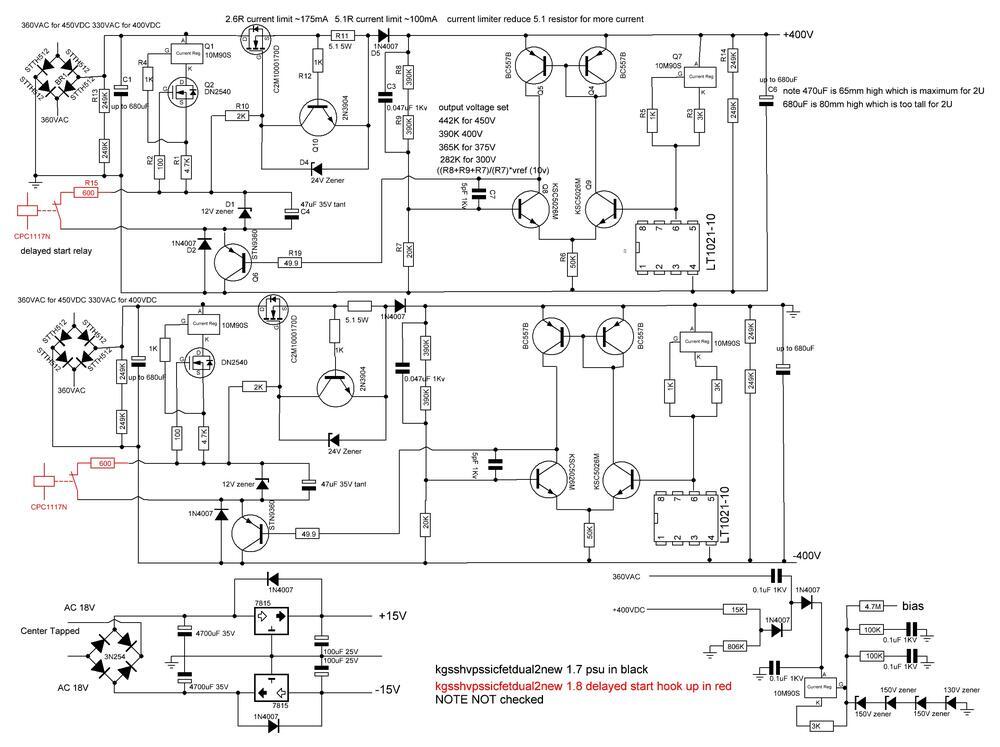


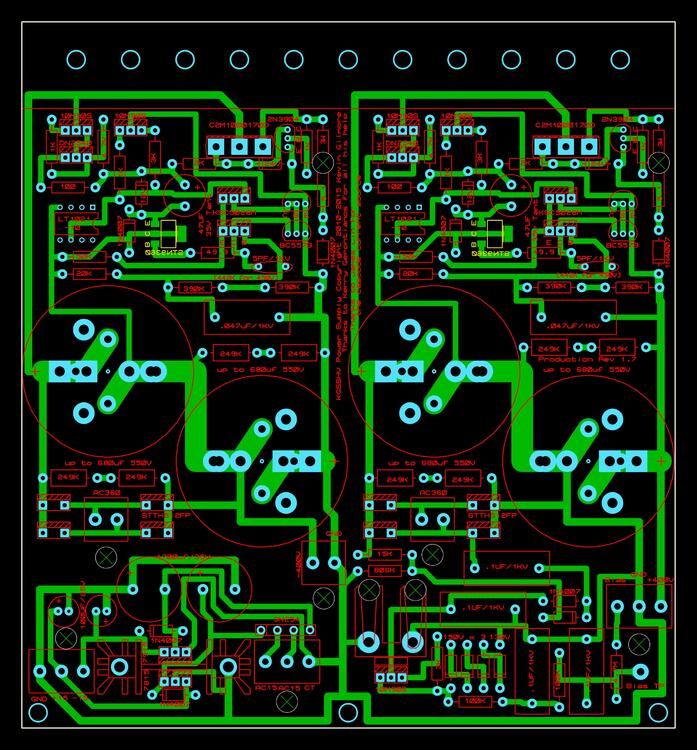
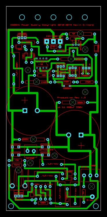
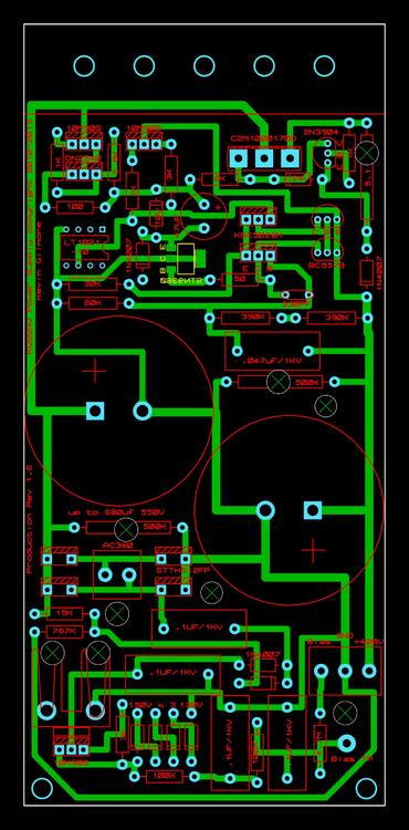
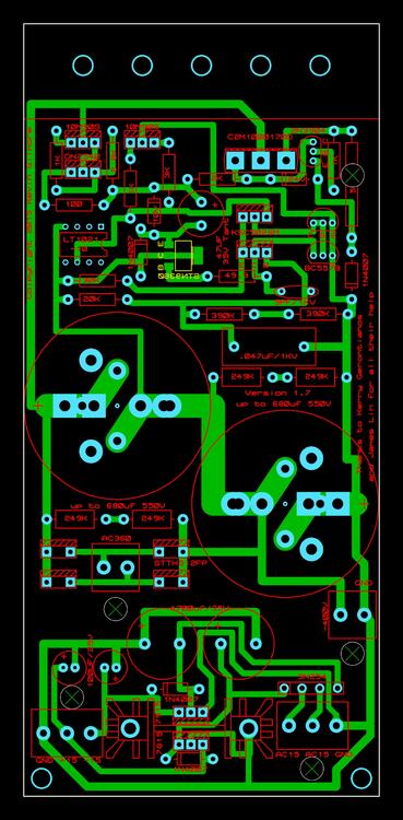
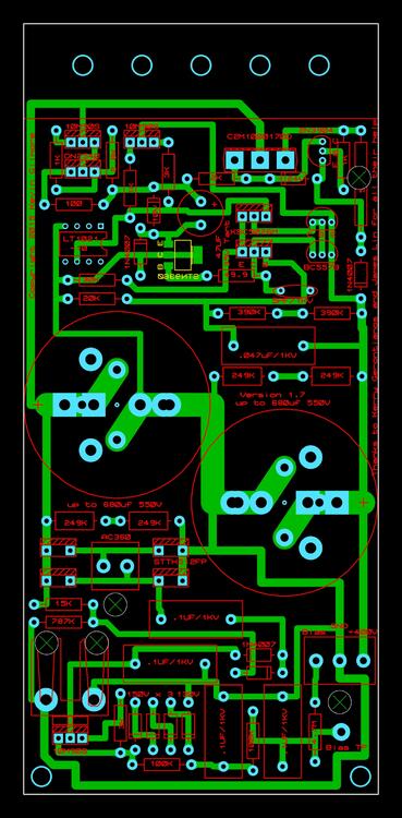
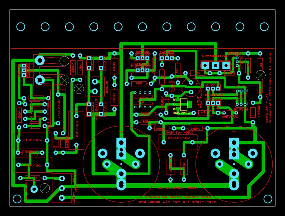
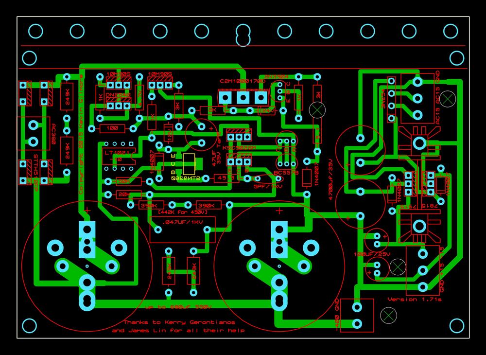
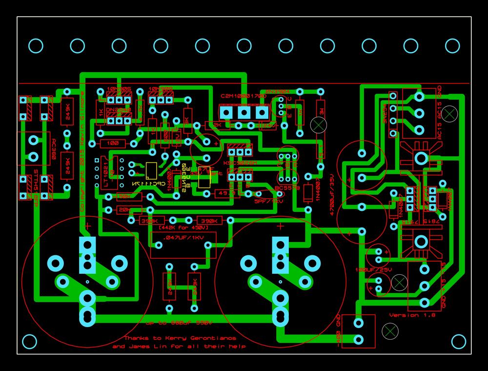
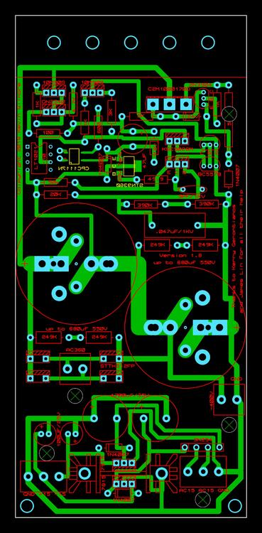
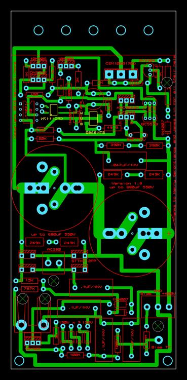
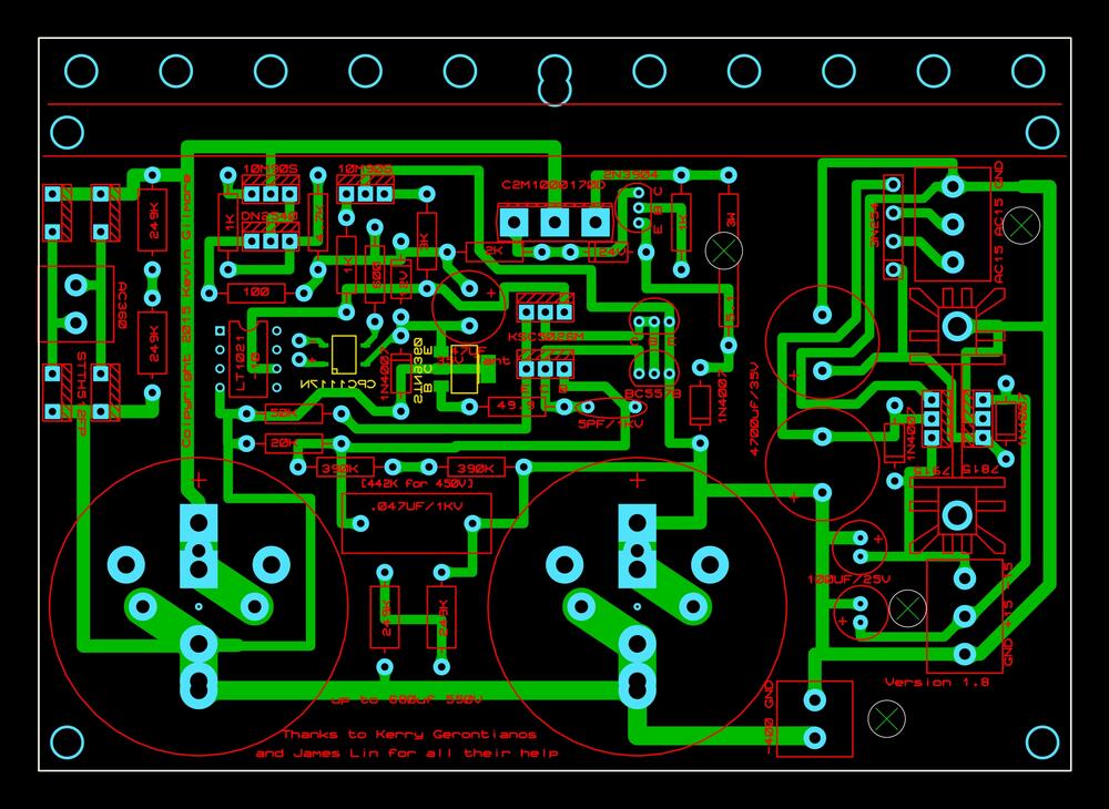
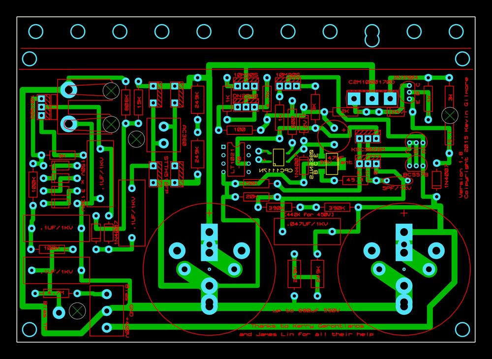
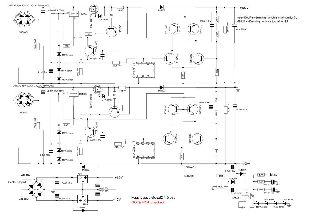
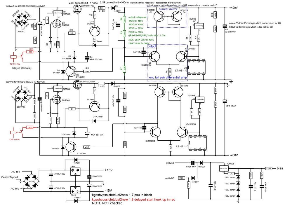
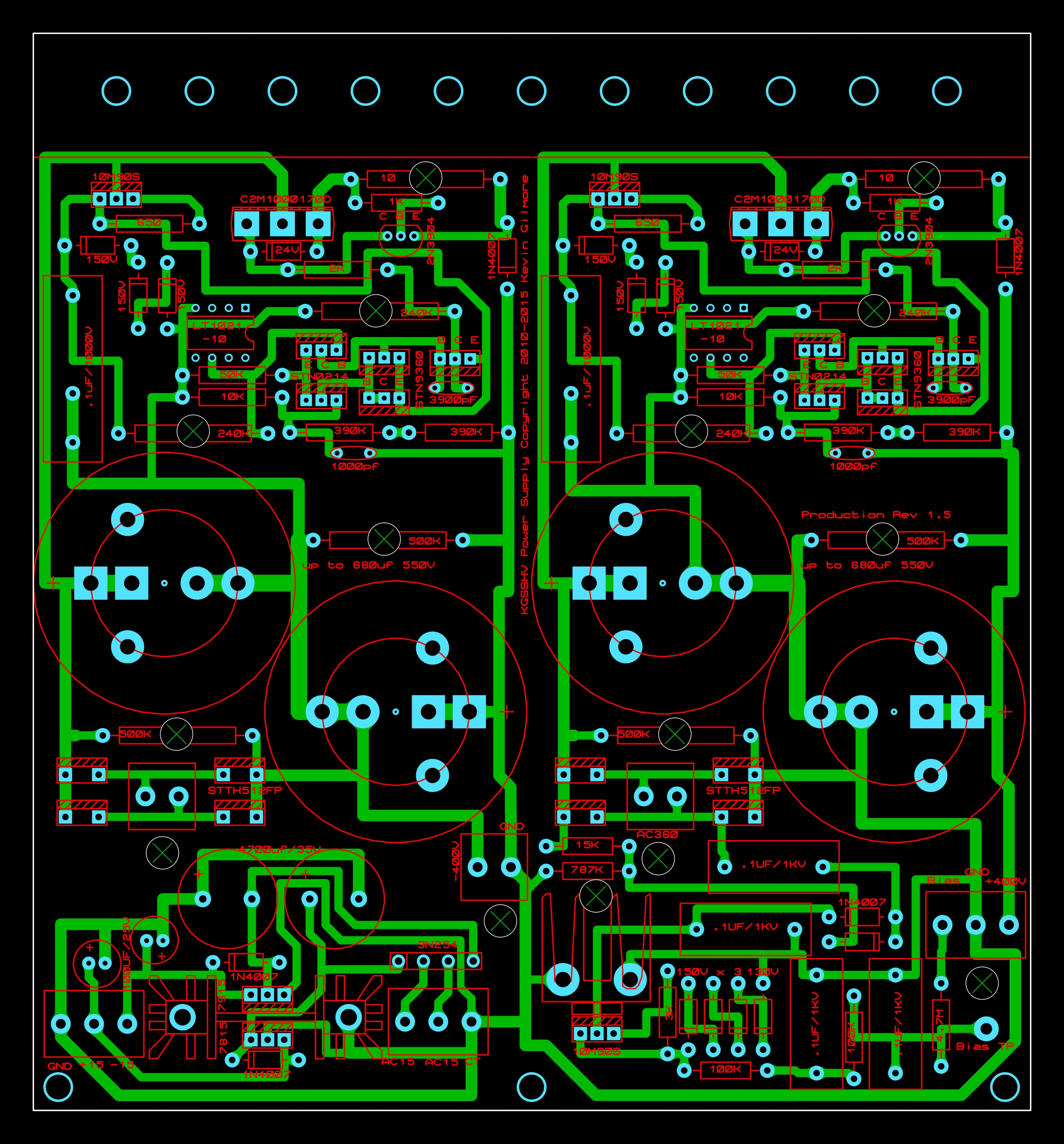
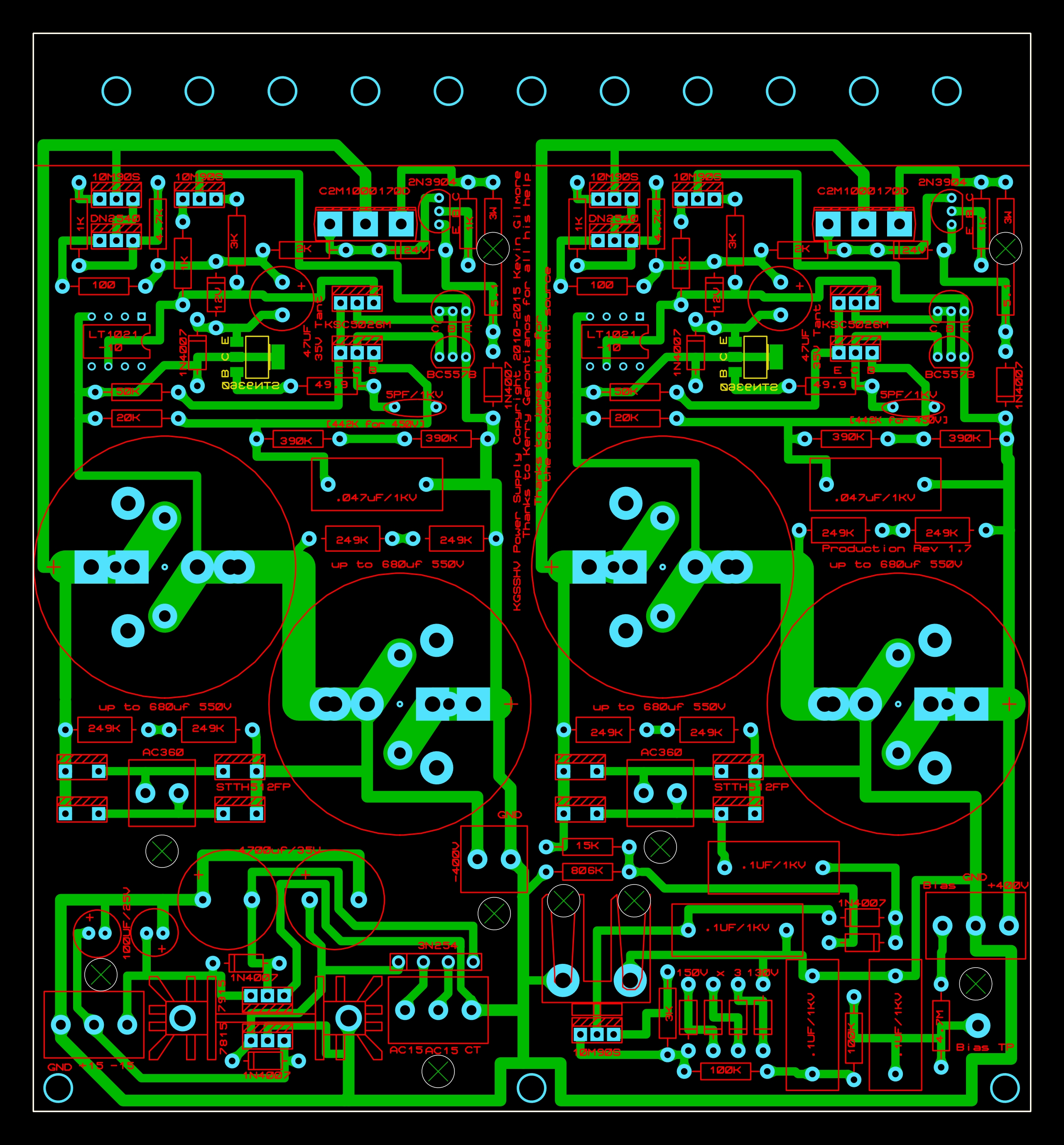
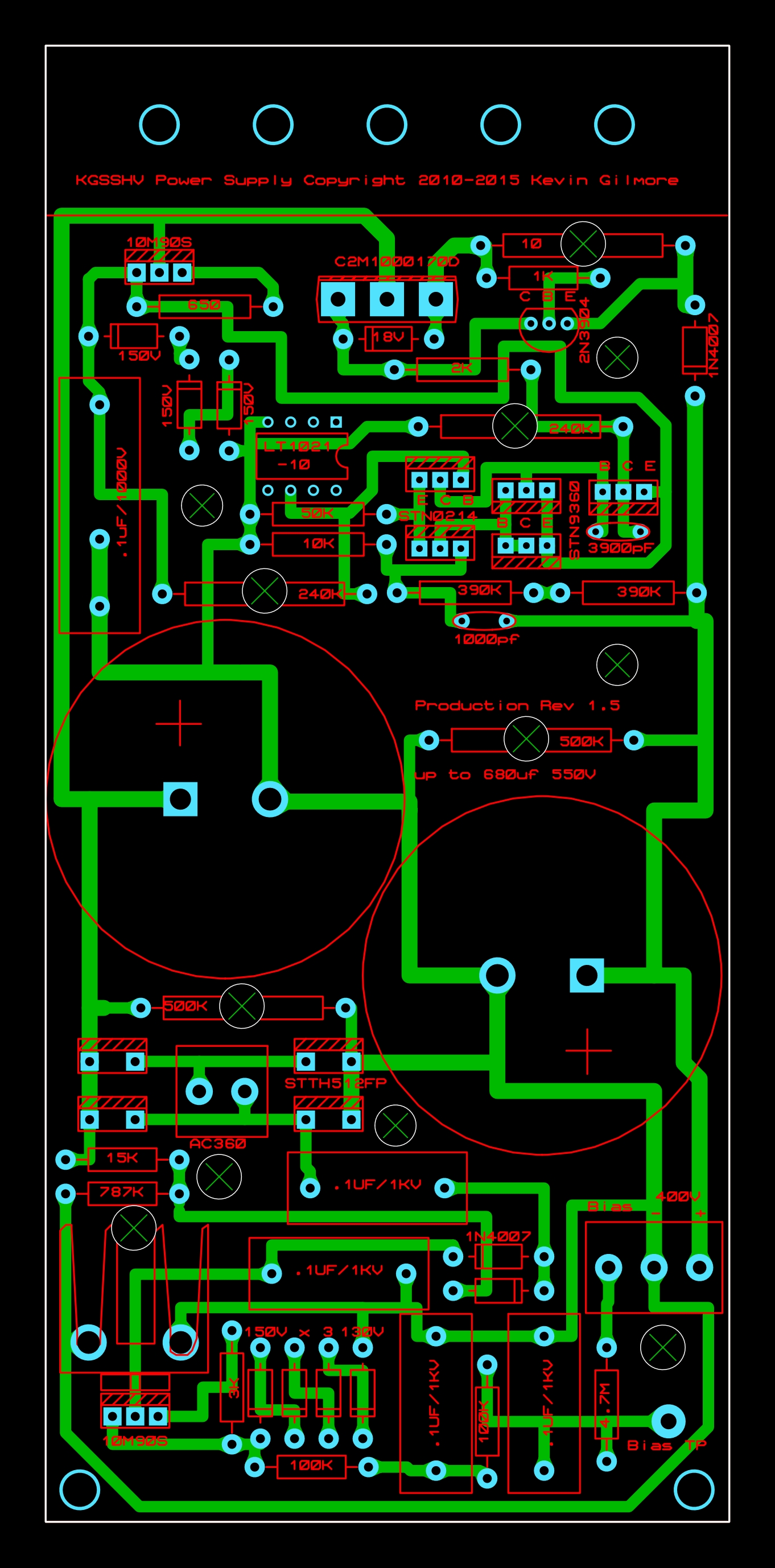
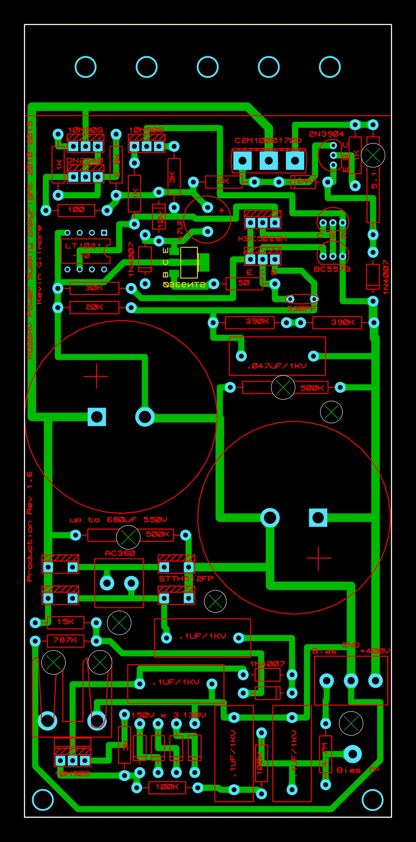
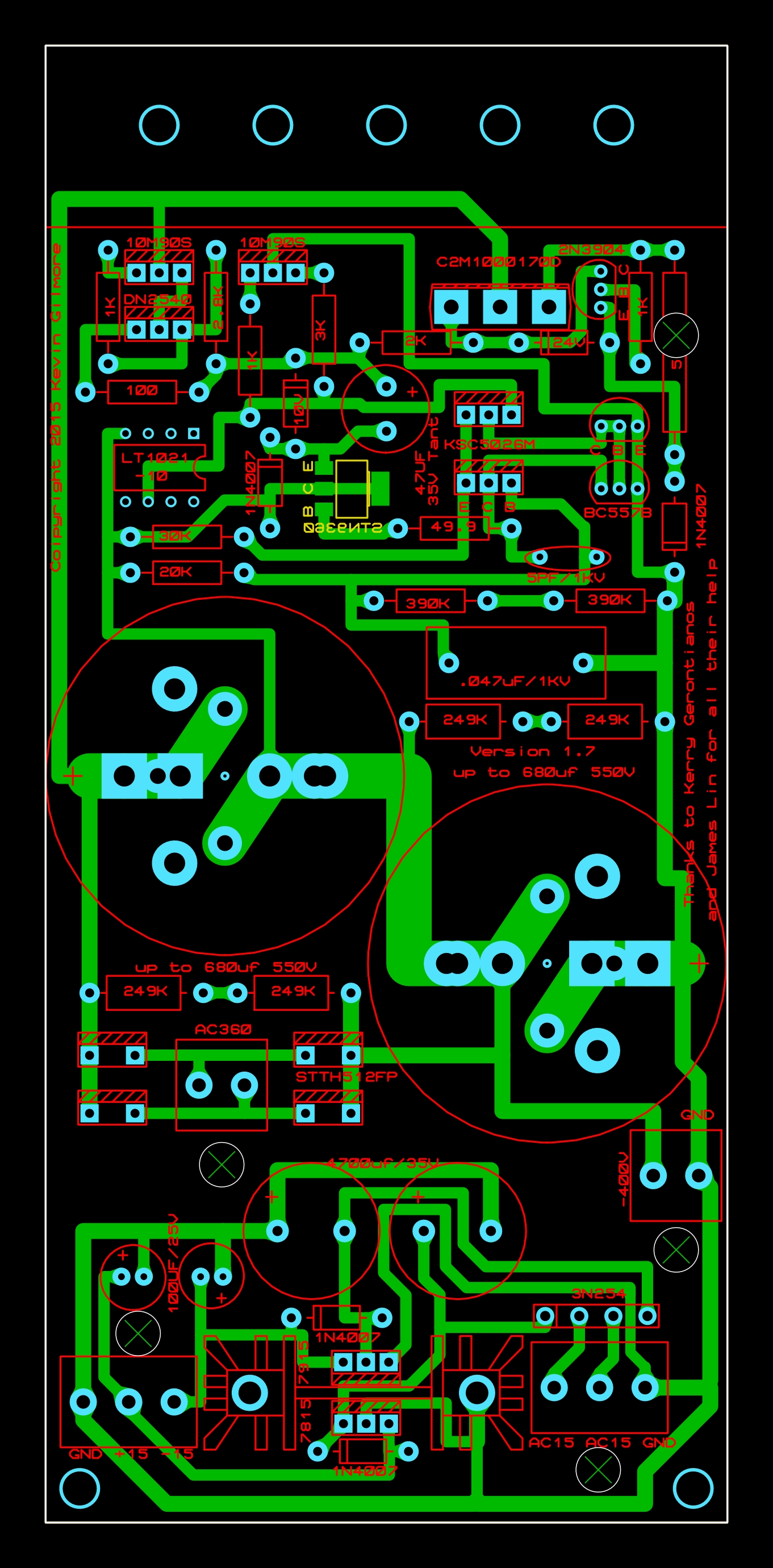
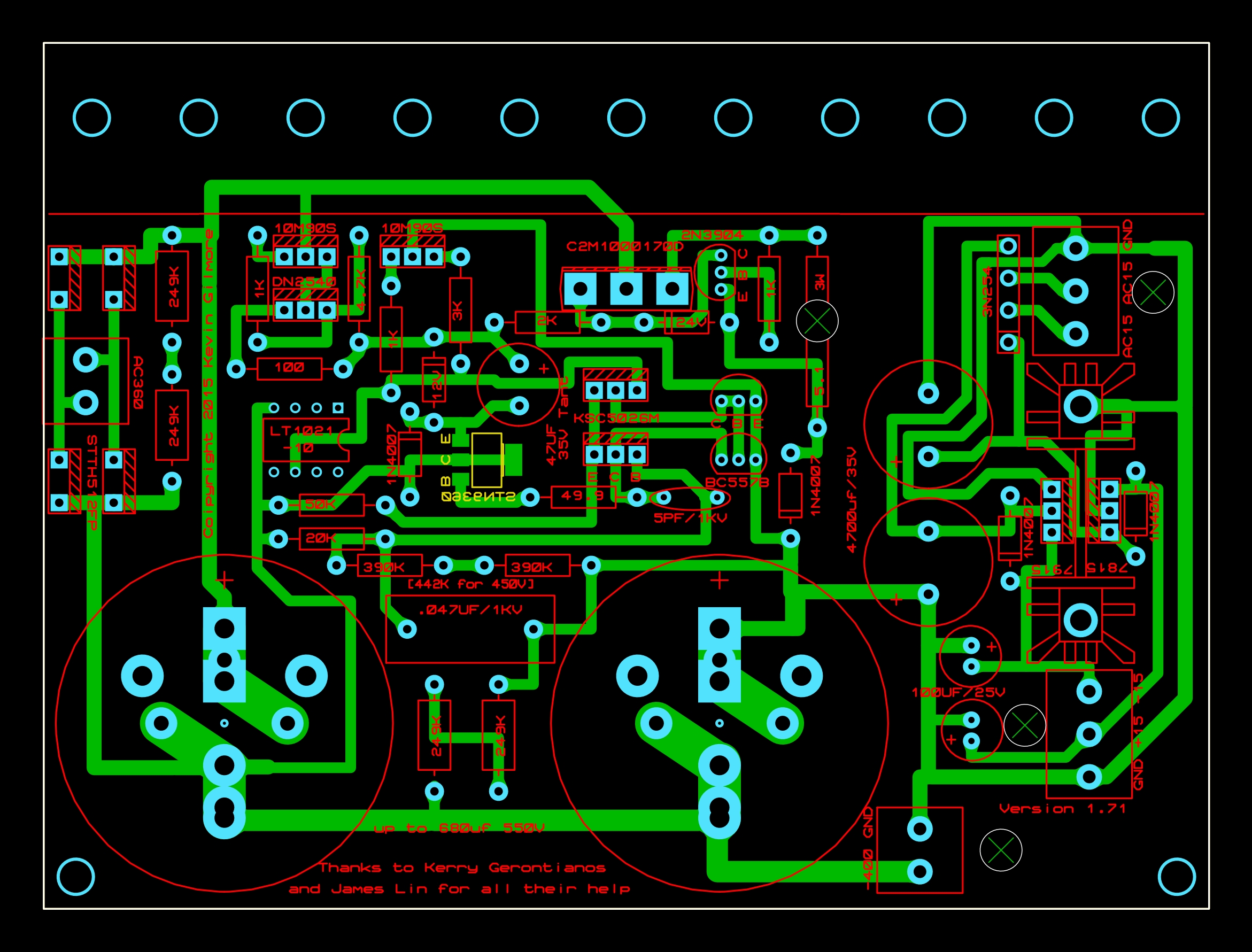
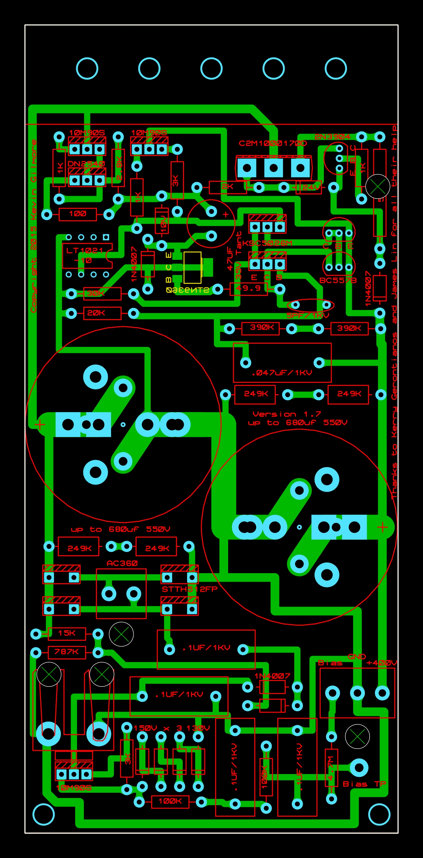
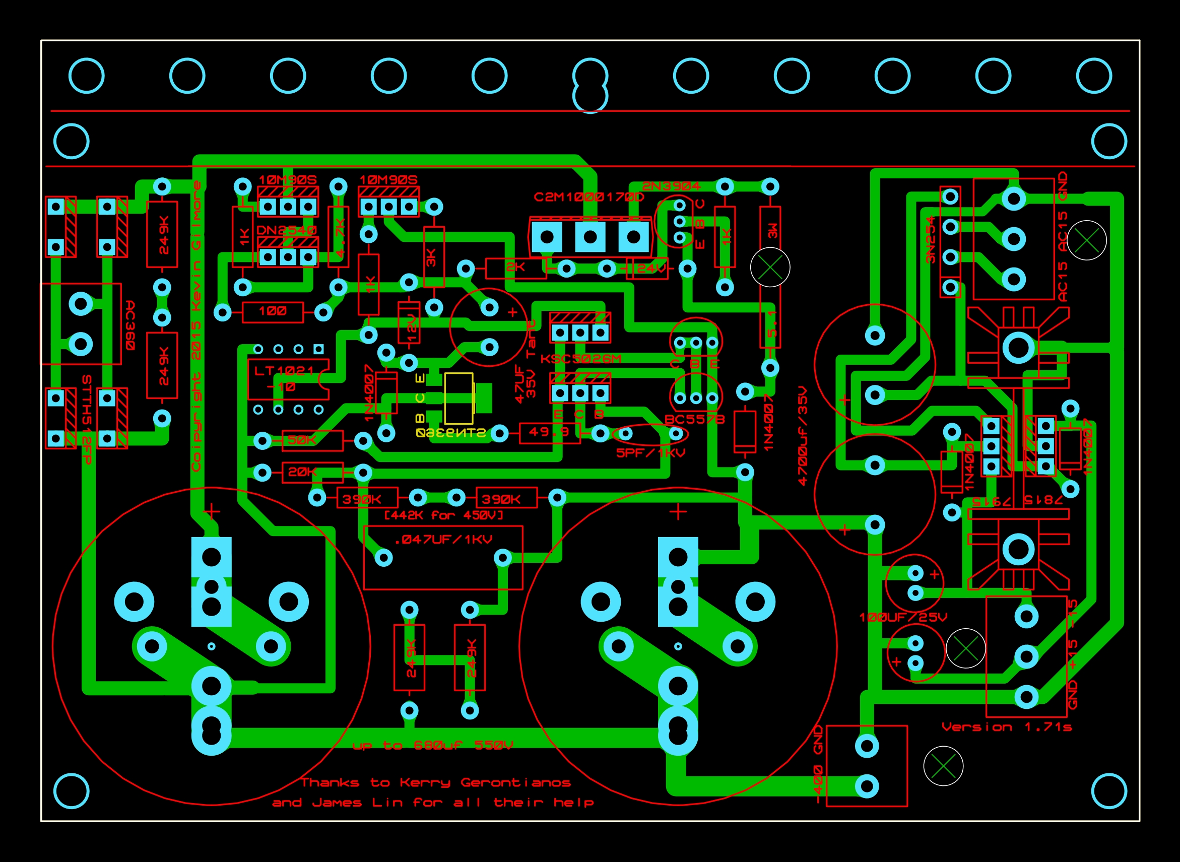
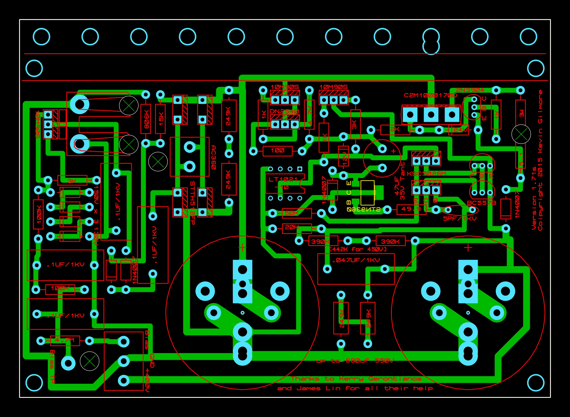
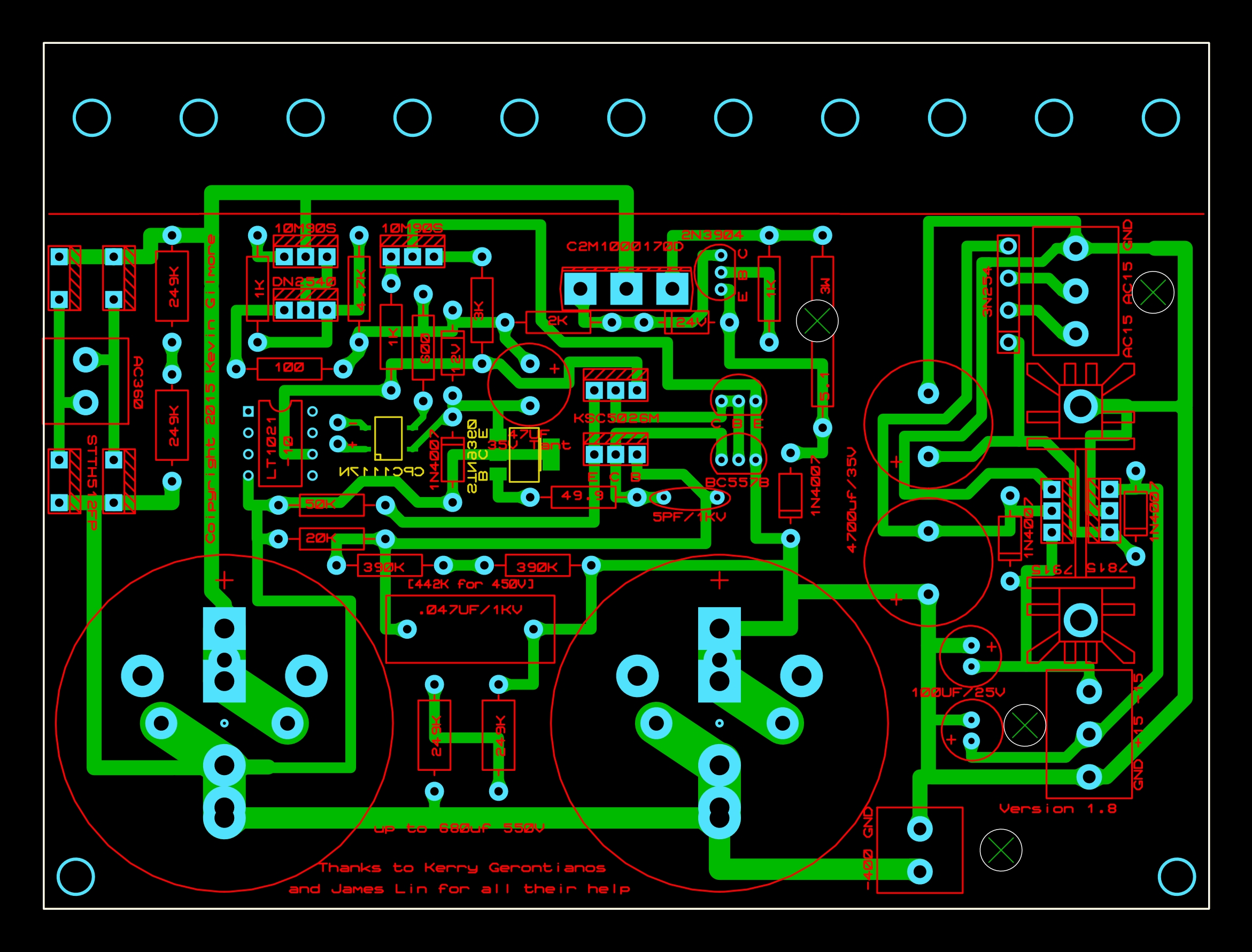
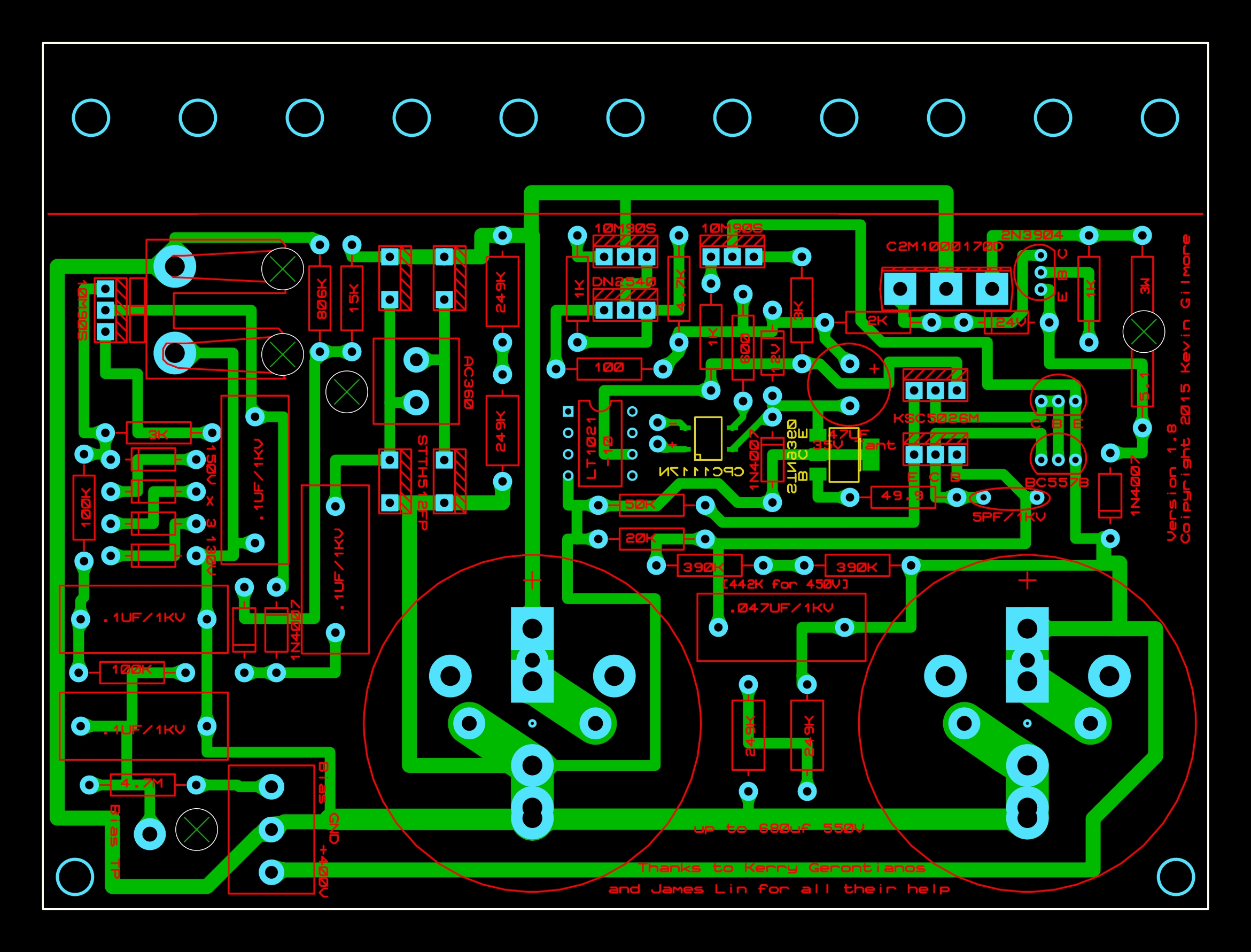
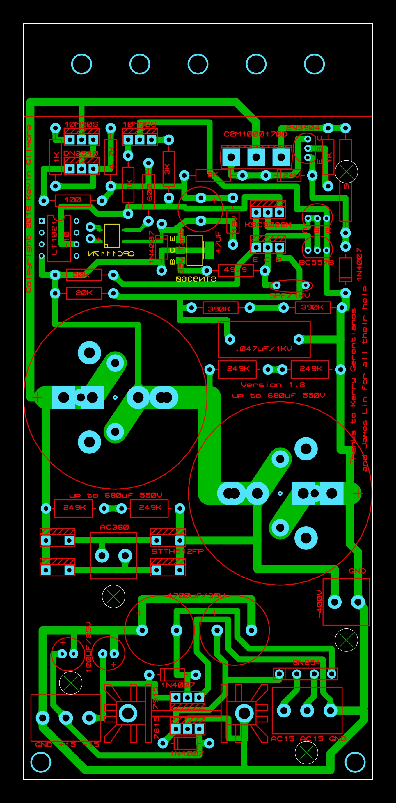
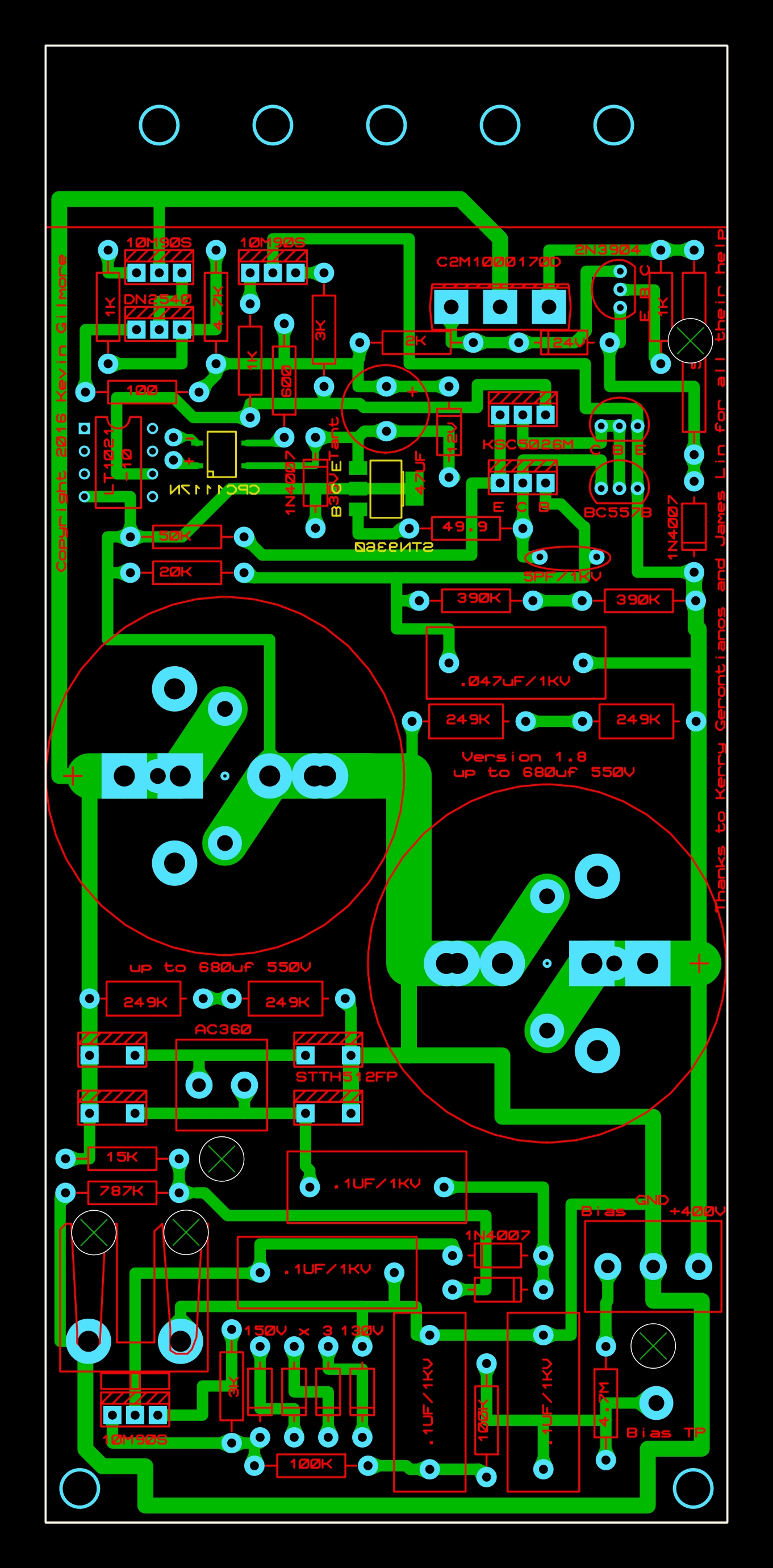
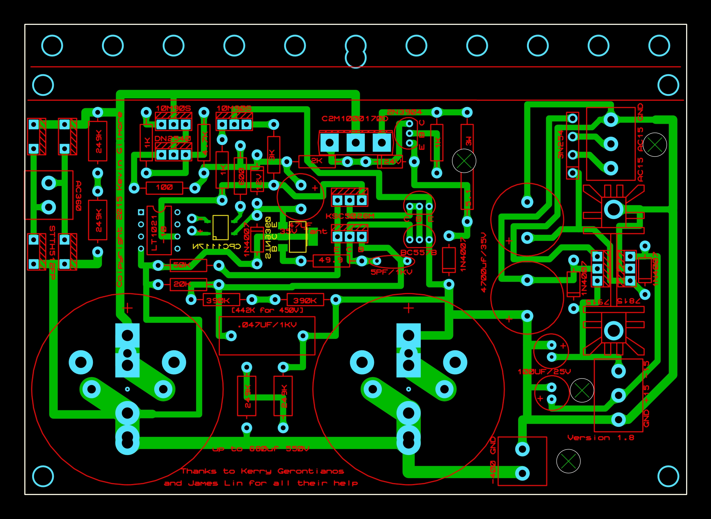
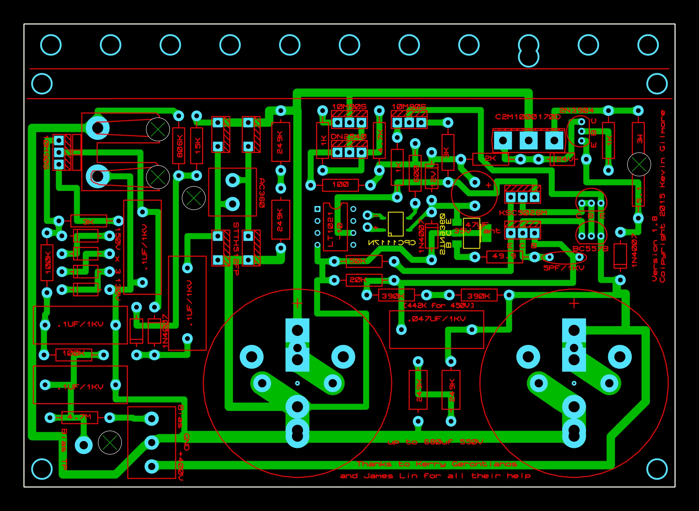
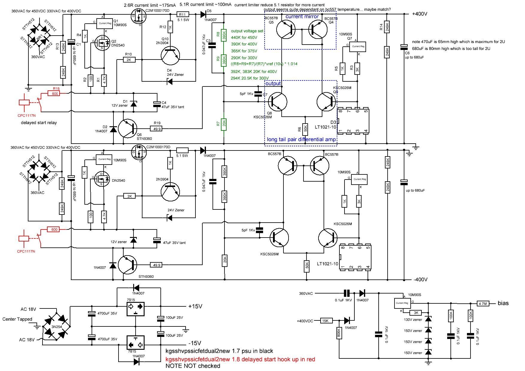
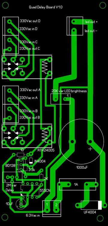 1 pointMy guide to golden reference high voltage (grhv) variants Here is my attempt at documenting some of the different GRHV board variations. (this will be work in progress for sometime) feel free to private message me with any additions comments, corrections etc. please note the schematic for version 1.5 has been reverse engineered by me from the gerbers and may contain error(s). location of the gerbers: https://drive.google.com/drive/folders/0B_iJFfZStuVhSE5nOHBVdTByR1k golden reference filename naming guide fat - boards which are wider and have less height than the non fat variants L bracket mounting only same as the non fat variants. fat with S as the last character of the filename - boards which are wider and have less height than the non fat variants and the height is about 6.3mm less than the fat variant. these boards also feature more screw hole options for the mounting the pcb to the case including an option of not using an L shaped bracket and mounting the transistors directly to the vertical face of a heatsink/side of the case. a silkscreen cut line is included to guide removal of the L bracket mounting roles to facilitate direct transistor to heatsink mounting. dual - has both positive and negative hv supply with additional bias and both positive and negative low voltage supplies on a single pcb left - has a single negative hv rail and both positive and negative low voltage supplies right - has a single positive hv rail and bias no new in the filename version - 1.5 boards high voltage starts instantly board has high voltage VAC power. Topology is much simpler then version 1.7 and 1.8 and therefore not considered golden reference. new in the filename actual golden reference boards with extensive post pass transistor regulation. new without sw in the filename- version 1.7 high voltage starts instantly board has high voltage VAC power. new with sw in the filename - version 1.8 or later boards same topology as 1.7 but high voltage will not start until dc power supplied to the cpc1117n no dual and no fat in the filename - minimal width and quite high. NOTE placement of the screw terminals for input VAC can vary considerably depending on if the board is a fat, fat S or non fat. Overview of the versions It is the extensive post pass transistor regulation that marks the golden reference out from the other power supply designs as such version 1.5 and earlier not classify as a golden reference since they lack any post pass transistor regulation. No details of versions before 1.5 or version 1.6 could be found in the gerber archives. Apparently pre 1.5 versions had on board heatsinks and ground lanes but there gerbers and not available in the google drive archive. No schematic could be found for version 1.5 although after reverse engineering it was found that the circlotronps.pdf is similar in topology but modified to support 900V output. No bill of materials could be found for version 1.5 and it is not certain what is the power rating for the larger resistors. All versions have the pcb tracks on the underside with no tracks on the top. All versions have no ground plane ALL versions have bleed resistors to help discharge the high voltage caps although version 1.5 and a few variants of 1.7 use a single high power resistor and the rest two 1/2W resistors in series. All versions have the same basic voltage regulator based low voltage positive and negative supplies All versions have the same bias supply although v1.5 has different resistor values. ALL versions use a LT1021-10 voltage reference All the versions 1.5, 1.7 and 1.8 use a C2M1000170D pass transistor All the versions use a 10M90S pre regulator although version 1.5 controls it with a zener string and 1.7 and 1.8 control with a DN2540. 1.7 and 1.8 are almost identical in topology although 1.8 does not automatically start the high voltages. DC must be applied to the CPC1117N to start. note 1.8 does not have provision for screw terminals for the DC to switch on the cpc1117n. versions 1.7 and 1.8 have more post regulation using a second 10m90s (which is not present in version 1.5) after the 1N4007 protection diode. version 1.5 uses a 10ohm current sense resistor and versions 1.7 and 1.8 use 5.1ohm by default. version 1.5 uses a 10K resistor to ground in the 3 series resistor chain to decide the output voltage, 1.7 and 1.8 use 20K to get 400V output. The other 2 resistors in the chain are the same for version 1.5 and version 1.7/1.8 version 1.5 uses two stn0214 which are replaced by two KSC5026M in v1.7/1.8 version 1.5 uses two stn9360 which are replaced by two BC557B in v1.7/1.8 Known non golden reference boards which are variations or predecessors to version 1.5 and golden reference variants NOTE These have not been looked at in detail by me or fully reverse engineered. The cyclotron power supply series follows a similar evolution to the golden reference. earlier cyclotron psus (circlotronps.PDF) use a variation of version 1.5 topology with modifications to bring the output up to 900V. However since it lacks any post pass transistor regulation it can not be considered a golden reference these psus do not have new in their name. The later cyclotron power supplies have the words new or newver in their name on quick inspection of the gerbers appear to be modifications for 900V of the version 1.7 power supplies, have post pass transistor regulation and may be considered golden reference variants. The filename conventions follows the guide above with dual, single, S and SWS versions available. circlotronhvpowerdualnew.zip appears to be derived from the version 1.7 topology with a similar complement of transistors. On the underside of the pcb there are two additional stn0214 transistors compared to the version 1.7 plus 3 mount points for a total of 500V worth of smd zeners. circlotronhvpowerdualnewer2.zip ditches the zener string and introduces another stn3960 and includes sw and sws variations. The kgsshv8g.pdf power supply appears to be an predecessor version of version 1.5. There are very close similarities in topology including no post pass transistor regulation. Current sense is still controlled by a 2n3904. The pre-regulator is 10m90s controlled by a zener string and a quad of transistors like the version 1.5. However the pass transistor is two parallel fqpf8n80c. The control transistors are 2sa1486 instead of stn9360 and 2sc3840 instead of stn0214. Both types of control transistor are no longer in production and hence the conclusion this is older than version 1.5. Apparently these boards are classified as KGSSHV ------------------------------------------------ Version 1.5 boards ------------------------------------------------- predecessor to the golden reference with no post pass transistor regulation the board uses a single high wattage bleed resistor for each cap uses multiple stn9360s, stn0214s uses a serial zener string for to control the 10m90s pre regulator. LT1021-10 voltage reference based single sided board kgsshvpssicfetdual2.zip this has both positive and negative rails, a simple voltage regulator based low voltage positive and negative supply and 580V for stax headphones bias board size approx. width 152.7mm height 165mm silkscreen revision 1.5 kgsshvpssicfetsingle2.zip this has a single rail identical to the kgsshvpssicfetdual2 in topology and 580V for stax headphones bias board size approx. width 76.5mm height 165mm silkscreen revision 1.5 ------------------------------------------------ Version 1.7 boards ------------------------------------------------- considered the first known golden reference board version (given the lack of information on version 1.6) has extensive post pass transistor regulation. the board uses two serial bleed resistors for each cap uses a single stn9360s and multiple BC557B and KSC5026M uses dn2540 and 10m90s for stage early voltage control for the input to the c2m1000170D LT1021-10 voltage reference based double sided board kgsshvpssicfetdual2new.zip this has both positive and negative rails, a simple voltage regulator based low voltage positive and negative supply and 580V for stax headphones bias board size approx. width 152.7mm height 165mm silkscreen revision 1.7 kgsshvpssicfetsingle2new.zip this has a single positive rail identical to the kgsshvpssicfetdual2new in topology and 580V for stax headphones bias board size approx. width 76.5mm height 165mm silkscreen revision 1.7 single bleed resistor for each cap kgsshvpssicfetsinglenewleft.zip this has a single negative rail identical to the kgsshvpssicfetdual2new in topology and has a simple low voltage positive and negative regulators based supply board size approx. width 76.4mm height 165.3mm silkscreen revision 1.7 kgsshvpssicfetsinglenewright.zip this has a single positive rail identical to the kgsshvpssicfetdual2new in topology and bias supply board size approx. width 76.4mm height 165.3mm silkscreen revision 1.7 kgsshvpssicfetsinglenewleftfat.zip this has a single negative rail identical to the kgsshvpssicfetdual2new in topology and has a simple low voltage positive and negative regulators based supply board size approx. width 138.7mm height 103.1mm silkscreen revision 1.71 kgsshvpssicfetsinglenewrightfat.zip this has a single positive rail identical to the kgsshvpssicfetdual2new in topology and has a 580v stax bias supply board size approx. width 138.6mm height 103.1mm silkscreen revision 1.71 kgsshvpssicfetsinglenewleftfatS.zip this has a single negative rail identical to the kgsshvpssicfetdual2new in topology and has a simple low voltage positive and negative regulators based supply has more mounting options for the pass transistor, 4 holes for mounting to a case and can be used with or without an L shaped bracket board size approx. width 138.7mm height 98.6mm (slightly less height than the fat non S version silkscreen revision 1.71s kgsshvpssicfetsinglenewrightfatS.zip this has a single positive rail identical to the kgsshvpssicfetdual2new in topology and has a bias supply has more mounting options for the pass transistor, 4 holes for mounting to a case and can be used with or without an L shaped bracket board size approx. width 138.7mm height 98.6mm (slightly less height than the fat non S version silkscreen revision 1.71s ------------------------------------------------ Version 1.8 boards ------------------------------------------------- same topology as version 1.7 making this a golden reference board adds a cpc1117n and 600ohm resistor to control high voltage startup the high voltage will not start-up automatically. This negates the need for a external relay for delayed start-up and just requires dc power to be supplied to the cpc1117n (not present in earlier versions) for the high voltage to start-up. if you want the board to power up instantly simply omit the 600ohm resistor and cpc1117n and it will act just like the version 1.7 instant start boards. boards same size as the equivalent version 1.7 pcbs silkscreen 1.8 there does not seem to be a dual version of this board kgsshvpssicfetsinglenewleftSWS.zip this has a single negative rail almost identical to the kgsshvpssicfetdual2new in topology and has a simple low voltage positive and negative regulators based supply board size approx. width 76.4mm height 165.3mm silkscreen revision 1.8 kgsshvpssicfetsinglenewrightSWS.zip this has a single positive rail almost identical to the kgsshvpssicfetdual2new in topology and has a bias supply board size approx. width 76.4mm height 165.3mm silkscreen revision 1.8 kgsshvpssicfetsinglenewleftfatSW.zip this has a single negative rail almost identical to the kgsshvpssicfetdual2new in topology and has a simple low voltage positive and negative regulators based supply board size approx. width 138.7mm height 103.7mm silkscreen revision 1.8 kgsshvpssicfetsinglenewrightfatSW.zip this has a single positive rail almost identical to the kgsshvpssicfetdual2new in topology and bias based supply board size approx. width 138.7mm height 103.7mm silkscreen revision 1.8 kgsshvpssicfetsinglenewleftfatSWS.zip this has a single negative rail almost identical to the kgsshvpssicfetdual2new in topology and has a simple low voltage positive and negative regulators based supply has more mounting options for the pass transistor, 4 holes for mounting to a case and can be used with or without an L shaped bracket board size approx. width 138.7mm height 98.6mm (slightly less height than the fat non S version silkscreen revision 1.8 kgsshvpssicfetsinglenewrightfatSWS.zip this has a single positive rail almost identical to the kgsshvpssicfetdual2new in topology and has a bias supply has more mounting options for the pass transistor, 4 holes for mounting to a case and can be used with or without an L shaped bracket board size approx. width 138.7mm height 98.6mm (slightly less height than the fat non S version silkscreen revision 1.8
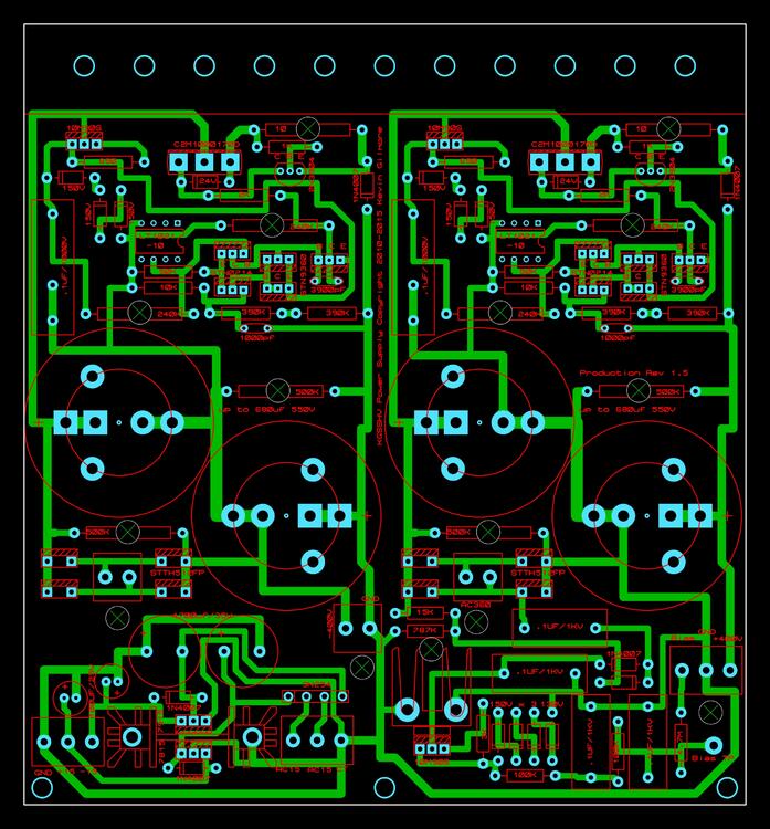


 1 point0 pointsRidley Scott is from my neck of the woods in the North East of England. The beginning of Blade Runner, with the gouts of flame harks back to his walk to school and back in the Winter in the dark. That passed close to the major chemical plants at that time, and they periodically burnt of waste gases in a gout of flame.0 points0 pointsIvan Reitman, Director of Ghostbusters and Stripes: https://www.vulture.com/2022/02/ivan-reitman-director-of-ghostbusters-and-stripes-has-died.html0 points0 pointsAh man, this thread is going to remind me how much I miss Steve... (rip again)0 points0 points


Important Information
By using this site, you agree to our Terms of Use.