

Leaderboard


Popular Content
Showing content with the highest reputation on 08/15/22 in all areas
-
I think it's just that you're not doing it correctly. I've posted the correct method in easy to follow steps... Step #1) pre-heat sufficiently heavy ceramic mug. Step #2) pour hot coffee into afore mentioned, heated ceramic mug. Step #3) swirl coffee around in ceramic mug to coat well. Step #4) pour coffee out of mug, into sink. Step #5) fill coated mug with Irish Cream Liqueur. Step #6) drink.4 points
-
Bah, this is HC, one thread is as good as another. My (state run) liquor store has the Flor 18 in stock for $39.99/750mL or maybe I should spring for something more in keeping with this place.4 points
-
3 pointsPicked this up recently and it’s really good. I have a few (dozen) rums. Always looking to expand.

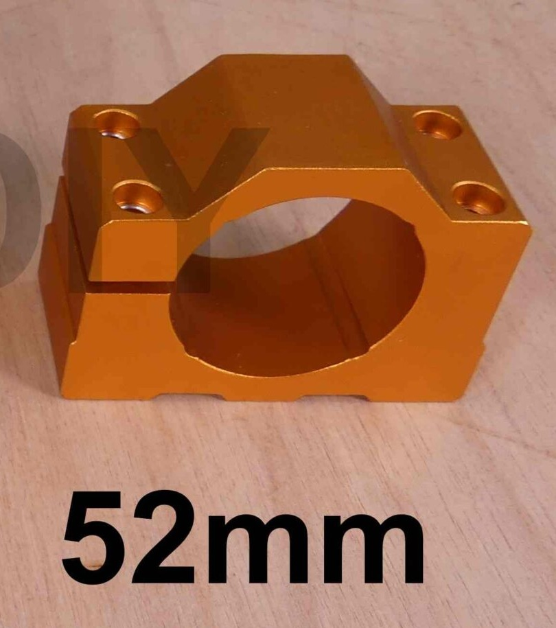
 3 pointsCharles Mingus Presents Charles Mingus (Remastered) Charles Mingus 1960 https://album.link/i/1610350703 Example: Good performance. But also made him sound like kind of a dick. Don't applaud, don't make any noise, just sit there and shut up and listen we are busy up here.3 points3 pointsThat's something that I've noticed in most of his recordings, they way they're mixed giving him prominence, the cover pictures... His live performances seem to reinforce that feeling of a guy being too glad of meeting himself for he's so important. Whatever, a fine musician nonetheless.2 points2 points1 pointthe diode lasers tend to come in rectangular aluminium blocks which have fins and act as heatsinks with a fan blowing downwards through the heatsink and a small controller on the top. The standard 400W spindle mount on my machine has 4 small notches in it so it can also mount the laser just by holding on to the corners. You don't need a high clamping force. So you could probably 3d print something if necessary. The hole is 52mm diameter. If you are planning to engrave or cut wood then additional air flow is recommended to clear the smoke (which would otherwise scatter the laser light) for aluminium engraving there seems to be no smoke. wow that spindle with quick change costs more than my entire cnc machine with the upgrades I have done so far.... My vfd and spindle is cheap chinesium, the only issues going that route is that there is a general lack of documentation and the seller could not help so i had to guess, experiment and look at you tube videos of similar setups for the vfd settings etc to get things to work. The vfd did come with a manual which was mostly understandable but although I purchased the spindle and vfd as a bundle the spindle had zero documentation and no information on how to set it up the vfd for it... the seller could not even tell me the diameter of the tubing required to fit the compression fittings on the spindle for the water cooling... so I had to guess and fortunately got it right first time. I also had to guess how many poles the motor had and use a tachometer to verify.... So if you are going chinesium I would ask the seller some questions about the tube diameters, motor poles, vfd settings etc and see if they have a clue before purchasing from them... Also I have found a general lack of attention to detail going chinesium, for example the vfd has three terminals marked earth. Two are totally isolated from everything including each other. Only one actually connects to the earth pin of the mains plug and the spindle takes a 4 pin plug, 3 for the power phases and you would assume the 4th pin is to ground the spindle body, nope no continuity to the body. Also on the vfd it has a temperature readout for the driver mostfets... always says 0C googling says this is normal temp never implemented....
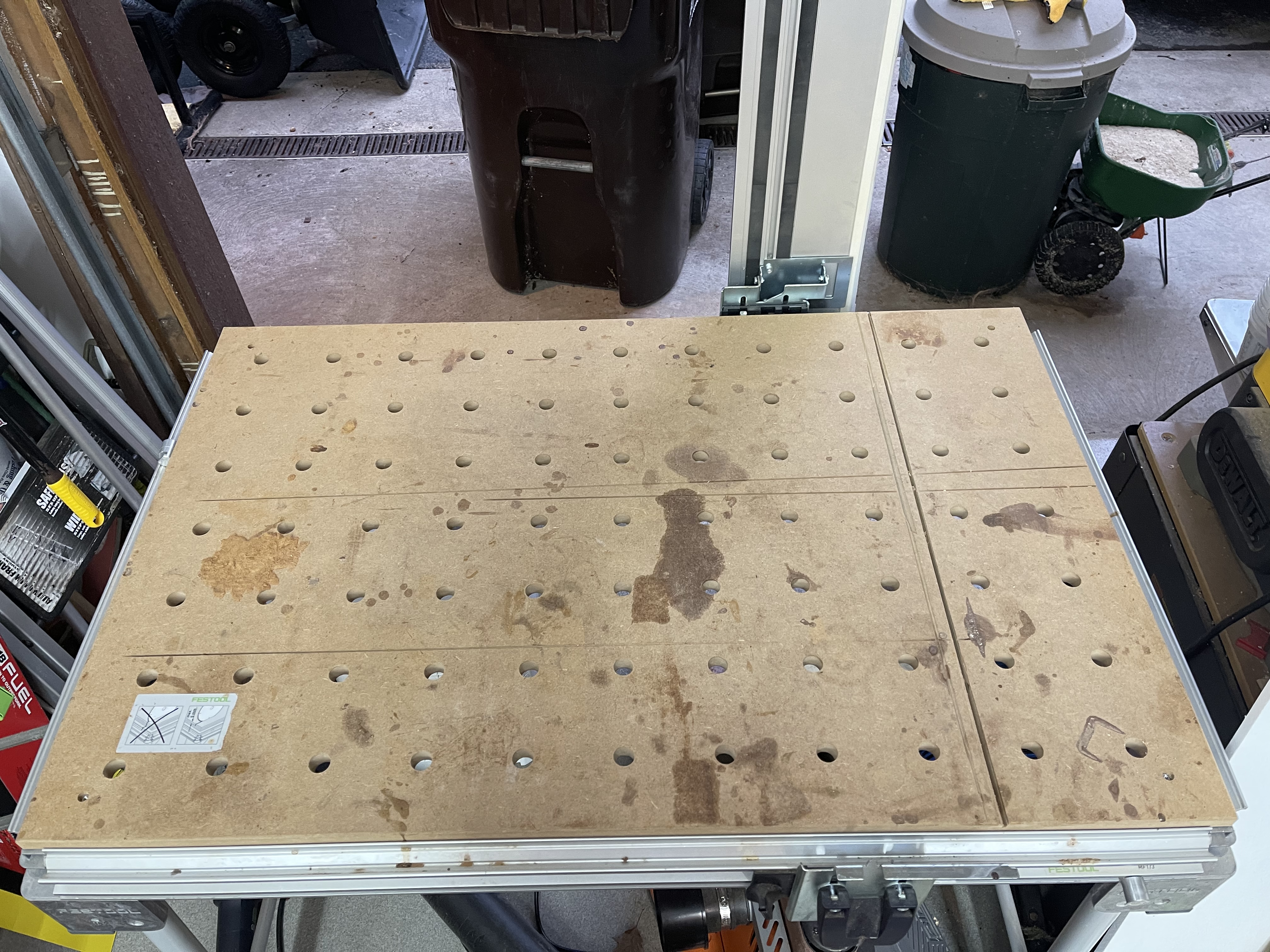
 1 pointAre you riding the full 1,000? A century seems like plenty. 😜 IN!1 point1 pointDecided to organize some drawers, walls and calibrate some seldom used Festool tools; router and jigsaw, as I thought I was going to build a new Paulk workbench so I can dump the MFT/3. That was until I priced the Baltic birch to build even the smaller workbench and decided to just flip the fucked up MFT/3 top and keep using this tiny thing for everything.
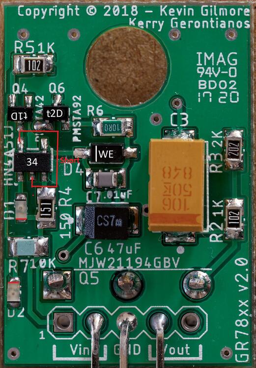
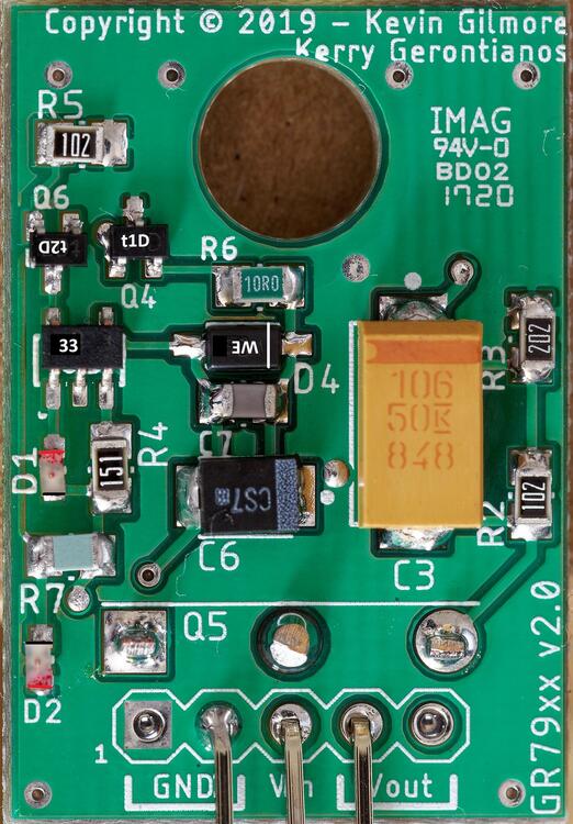
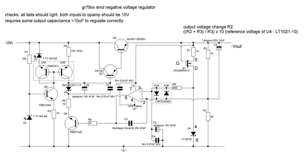
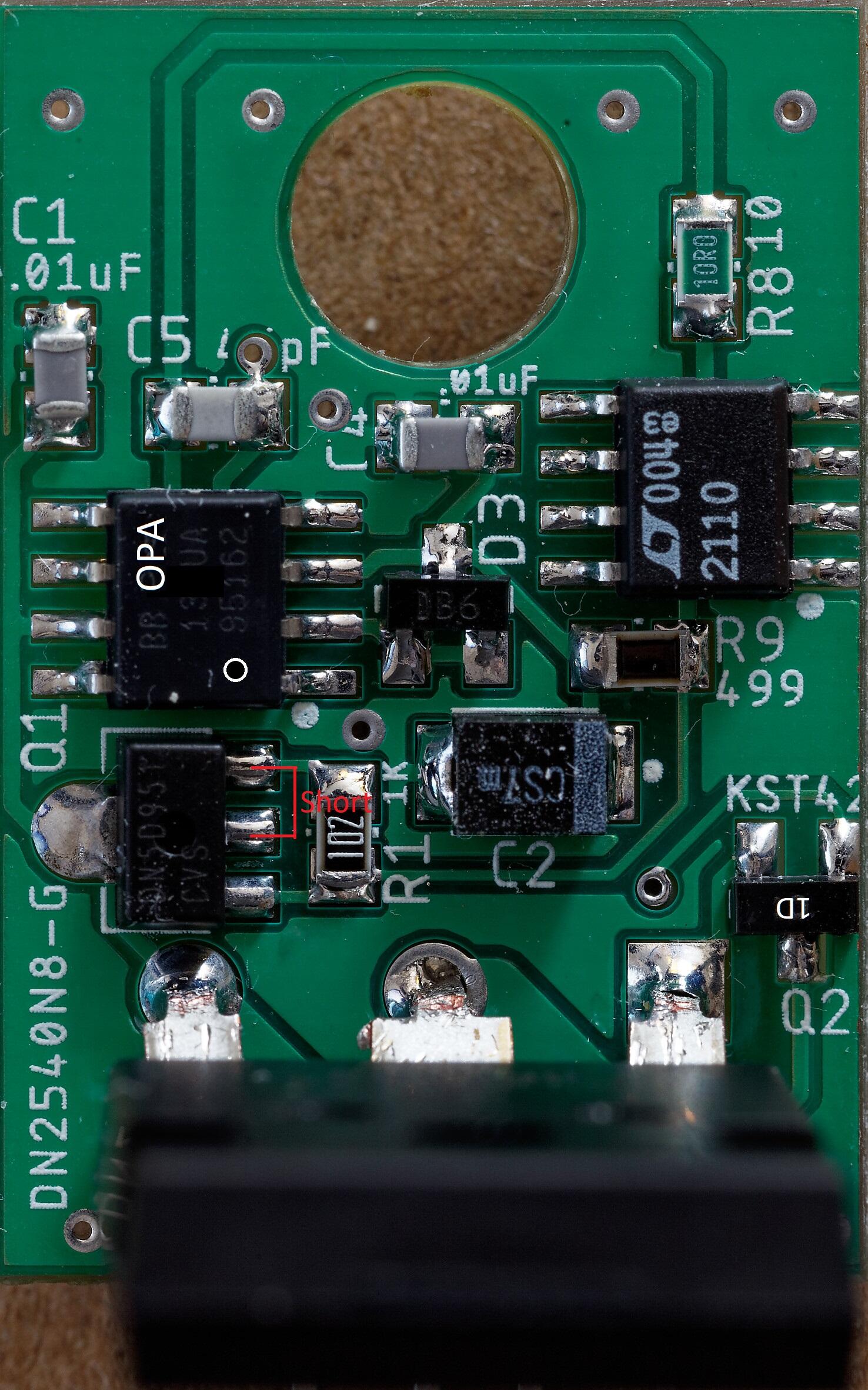
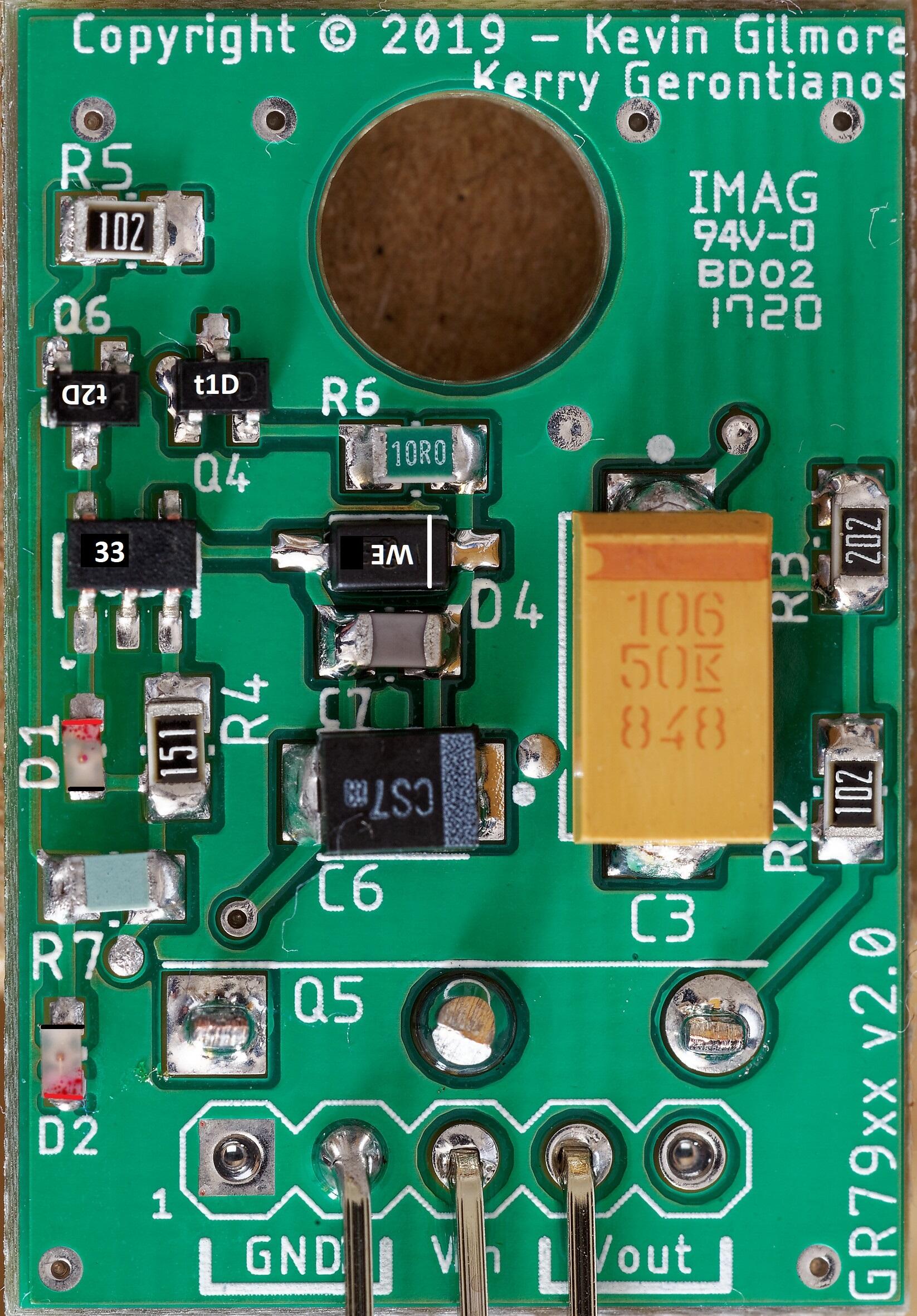
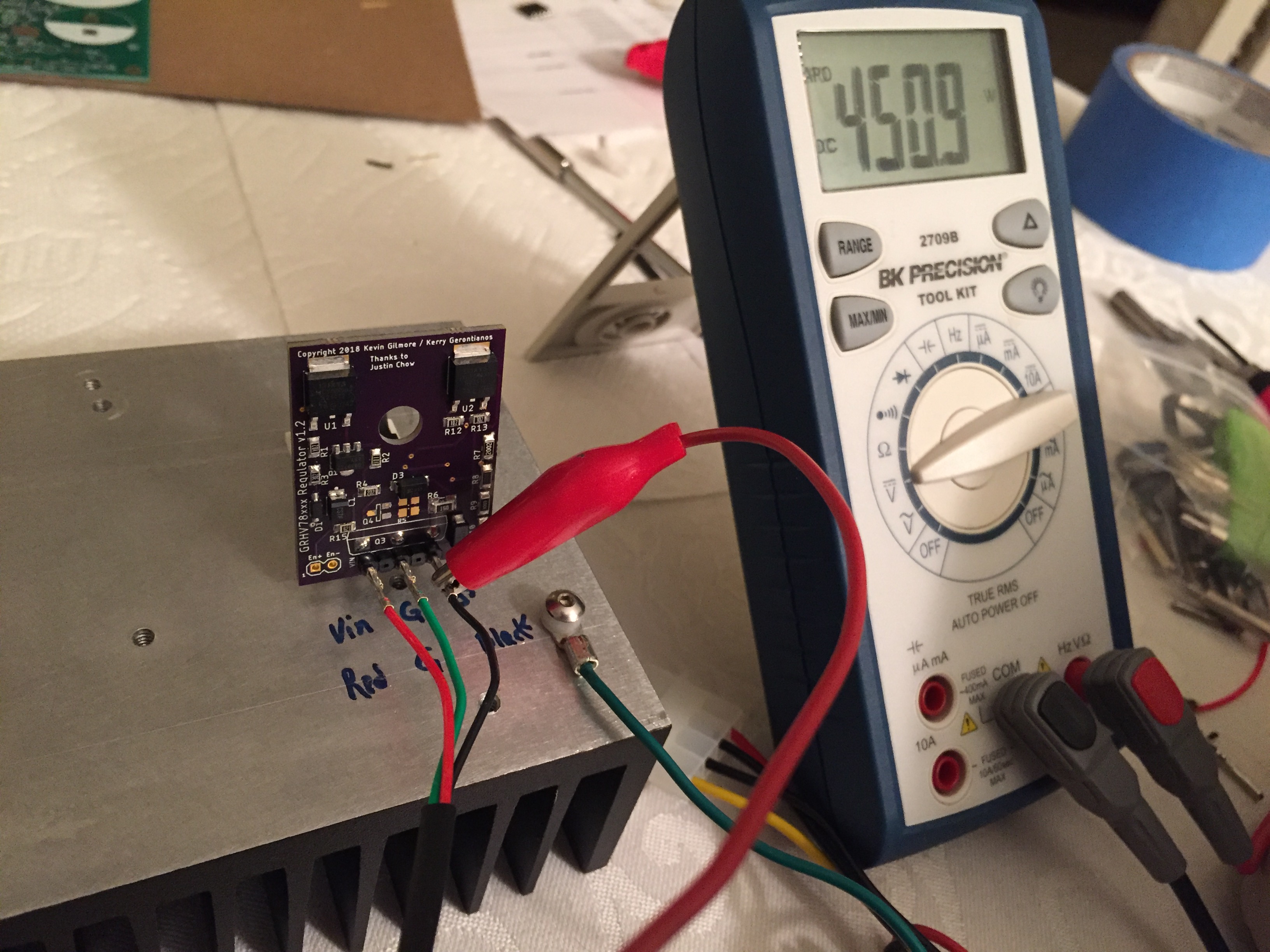
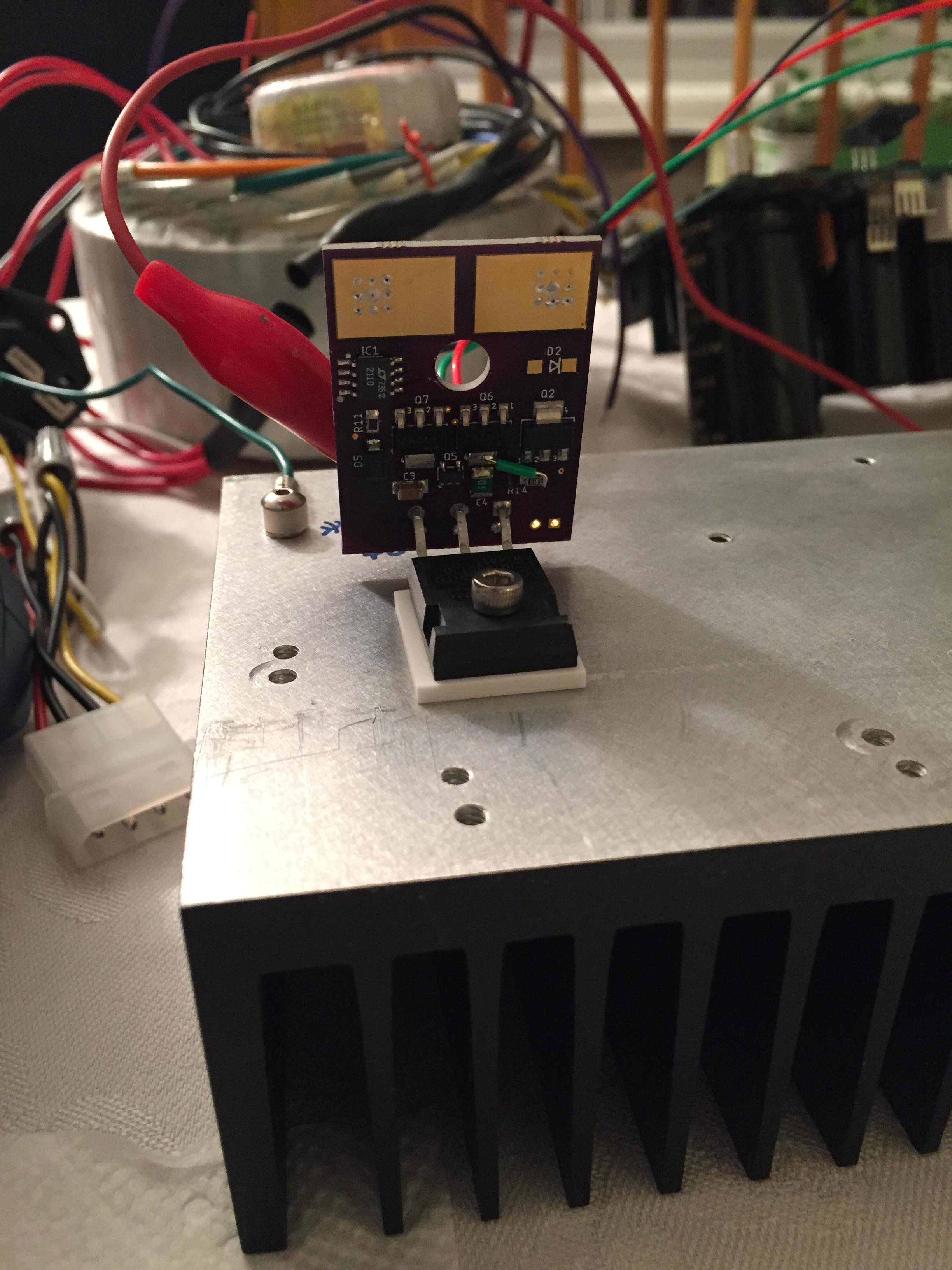
 1 pointJust now seeing this. In and done. As usual it's a privilege to help sponsor you for such a great cause. You are an inspiration!1 pointMaybe I’m not coffee snob enough, but I found Onyx to be good but nothing amazing. It’s readily available here since it’s almost local and a handful of places have it as their daily drip. I’ve actually never found any coffee to be good on the same level as a good beer/whiskey is. Maybe I just need to spike it more often 😂1 pointBuilt a Megatron. Seems to be the perfect amp to build during the seemingly unending shortage of 10m90s. I used up my final few pieces of 10m90s and C2M1000170D for this simple build, and it gave me some mild anxiety and regret for not hoarding up those sands. However, the build experience and result are worth it. Build process and after thoughts I started off with a pair of generic chassis from Taobao. 32cm wide, 8cm tall, 35cm deep. Silver and black anodised aluminium. They weren't available in other finishes but this looks clean enough to me. They do have some minor scratches and dents if you look hard enough though. The casework was done by a laser etching service provider I found on Taobao. The end result was a clean and modern appearance. Inside the PSU are a pair of +/-450V GRHV, +/- 15V GRLV, delay board and a 270VA toroidal transformer. The idea was to create a PSU that can be used by both the Megatron and the Grounded Grid amp units. These components fit the chassis nicely with little room for a third GRHV board for the 300v rail for Megatron. Outputs are split into AC and DC outputs. Transformer specs: The heatsinks for the amp unit were probably redundant since most of the heat comes off from the top. The amp board could probably fit into a smaller and lighter chassis, but I chose the same chassis as the PSU just so that they can stack. The amp build was straight forward and relatively easy compared to a Carbon build or any of the KG dynamic amp builds, due to the low component count. I did not use any boutique components in this build. The coupling caps are Wima, and the voltage rail decoupling caps are Siemens. Volume pot is an EIZZ-style stepped attenuator, internal signal wirings are pure copper. Special care was taken when routing the heater filament wires to avoid hum. Amp testing and adjustment was simple. Just ensure the all the rails are as spec'ed and that's about it. The voltage offset settles automatically after power on. No need to fiddle with any potentiometer when the amp is powered on, so it is much safer to test than the Carbon or the T2 family. Sound I used the Megatron with ES-1A, and here is my impression of the Megatron after comparing it with GG (on the same PSU), Carbon (450V GRHV 15V GRLV) and Mini T2 (triple GRHV). Currently I am using the Megatron with a quad of Mullard XF2 and PSVane EL34PH. The front end tubes are all Valvos. The sound of the Megatron is warm, slightly thick in the mids, and non fatiguing and airy in the treble. It sounds very natural and the imaging is holographic with good recordings. While it is very detailed, it does not ruin joy if the recordings are of poorer quality. Older or poorly mixed recordings have a smooth timbre and organic vibe when heard from the Megatron. While the Megatron's treble is not as extended as the Carbon's, it complements the overall signature to create a very complete soundstage and convincing sense of separation and space. What makes the Megatron standout from crowd lies in its low end - it is an amp for bassheads. It has by far the most THICC bass compared to my other amps, even more than the Carbon. The bass extends as deep as the Carbon, but the Megatron has a nice lift in the mid bass that makes my ES 1a slam extra hard. Listening to EDMs and fast pop tracks on E-Stats is finally satisfying, and I can finally stash away my planars. Carbon is like an antithesis to the Megatron. Carbon is like a clean cutting razor with little tolerance for inaccuracies where as Megatron adds a lot of joy and flavour into the listening experience. Carbon also sounds a little linear. Although the stage is wide, it is not as deep as the Megatron's. GG sounds more organic than Carbon in general. The GG's signature is quite dependent on the tubes. With the XF2s, GG is warm and clean, but doesn't deviate far from the Carbon sound. The bass isn't as tight and fast, and treble could sound stiff and slightly shrill with the wrong tubes - such as the re-issue Mullard EL34. Mini T2 sounds slightly leaner and cleaner than the Megatron, and has a much smaller bass. It is as enjoyable a listening experience for me, but the Mini T2 was much harder to build - by sheer component count. Tube placement and choices Placing the EL34s in this manner shown below allows one to use two matched quads of EL34 if matched octets are unavailable. Initially I used cheap Linlai tubes for the front end and had issues with sound imbalance and hum - turned out that the tubes were the culprits. Switched to some cheap NOS and the issues were gone. So my advice would be to use well built tubes from reputable makers. The 12AU7s affect the sound significantly. The option to roll tubes makes Megatron extra fun to use. More photos of the internals and the back of the amp coming up soon, when I am more free. I would say that the Megatron is my favourite amp - until I build the T2.1 pointGR78xx build notes: Writing direction on the opamp and voltage reference match the writing direction on the pcb I suggest checking the led orientation with a multi-meter in diode test mode, finding out which way round the multi-meter leads need to be to make the diode light and then marking either the positive end of the led with a red pen or the negative with a black pen whilst holding the led with twisters - if you don't hold the led with twisters it has a nasty habit of sticking to the pen tip. The leds face opposite directions. Positive and negative ends are marked in the picture with red and black lines respectively. All transistors are shown with their case markings. Its a good idea to solder the leds in first and then check. D2 has the end closest to the Vin pins connected ground and so its easy to check its orientation is correct, the other led is opposite orientation. The DN2540 is a depletion device so if you measure resistance between pins, two of the pins will appear to be shorted - this is normal and shown on the picture. The tab is also electrically connected to the centre pin... The top left pin of the hn4a51j is also connected to the bottom middle pin on the ocb and will therefore also measure as a short. The pmsta devices have 3 digit case codes the first digit being the place of manufacture, the kst devices have two digit codes. Be aware Both the pmsta42 and kst42 have codes 1D but the pmsta42 has a t or other letter before the 1D for the manufacturing location. voltage ref should have 10V between pins 4 and 6 If you test the board by itself it must have capacitance connected to the output in excess of 20uF in order to regulate and not do strange things like increase the output voltage when the load increases. When setup for 15V output, input voltages bellow about 1.7V should result in very little current draw <1mA and no leds lit . At around 1.7V input D2 show glow dimly and increasing the input voltage should result in D2 glowing brighter, the current draw increasing and the output voltage increasing. When D2 is fully bright the current draw should be about 10mA. At about 17.5V input D1 should begin to light . Increasing the input voltage further will make D1 brighter and the current draw increase towards 10mA current the draw when the led is fully bright. At around 18.3V input the output should stabilise at around 15V and increasing the input voltage further should have no effect on the output voltage or current draw. The second 78xx I built required 0.2V more to regulate fully despite having a 8mV lower output. Load testing Expect approximately a 23mV decrease in output for each 100mA of load current drawn from the gr78xx. At 200mA the components on the board should be warm but easy to touch and leave your finger on. The MJW211 should also be a little warm. NOTE the metal tab of the MJW is live so don't short it to something. Voltage drop under load test, no heat-sinking, MJW211 close up against the pcb, 18.3V input. The drop in output voltage is the same using a 47uF output cap as 220uF. 100mA 23mV drop 200mA 46mV drop 300mA 69mV drop 400mA 93mV drop 500mA 116mV drop (note tab of mjw gets too hold to touch for more than a moment after a few minutes of this load. heat-sinking recommended) The second 78xx I built had voltage drops within 2mV of the first. The voltage drop under load is a bit more than a traditional 7815 to-220 voltage regulator under the same conditions. Removing the load results in the output voltage of the gr78xx going back to within 1mv of the original no load output almost instantly, even from the hot 500mA load. the voltage drop is fairly linear with load. Otuput voltage drift under constant load as the device heats up or cools down is very low. LED direction verification for gr78xx lower led D2 multimeter in diode check mode red probe on top of led black probe on bottom (as indicated in photo bellow) you should get about 0.89V drop led will not light. probes reversed meter should say OL upper led D1 multimeter in diode check mode black probe on top of led red probe on bottom (as indicated in photo bellow) you should get about 1.66V drop led will light. probes reversed meter should say OL 79xx build notes All polar caps, Zener and LEDs are in the opposite orientation to the 78xx, All resistors are in more or less the same positions and orientations as the 78xx, all transistors that are xx42xx become xx92xx and visa versa. NOTE in the BOM Q6 and Q4 appear to be the same on both the 78xx and 79xx however, on the silk screen the physical positions of Q4 and Q6 swapped in all other cases the transistors change in the BOM rather than the silkscreen designations moving. The opamp and LT voltage reference are in the same orientation as the 78xx. The HN4A51J becomes HN4C51J and the MJW211 changes from 94 to 93. All positions that hold a KST device continue to do so and the same is true for the PMSTA. Only the type of device swaps from NPN or PNP i.e. from kst42 to kst92 and visa versa or pmsta42 to pmsa92 and visa versa. The 79xx has similar load behaviour to the 78xx. LED direction verification for gr79xx lower led D2 multimeter in diode check mode red probe on bottom of led black probe on top (as indicated in photo bellow) you should get about 0.89V drop led will not light. probes reversed meter should say OL upper led D1 multimeter in diode check mode black probe on bottom of led red probe on top (as indicated in photo bellow) you should get about 1.66V drop led will light. probes reversed meter should say OL
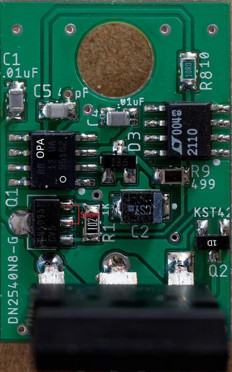


 1 pointI was able to get the 450v supply up and running. I did have one error on the board. The current source feeding the 10v reference gets up to 150 degree F, but I can add more copper around it. I think it will be just fine. I was running this with a 110mA load.
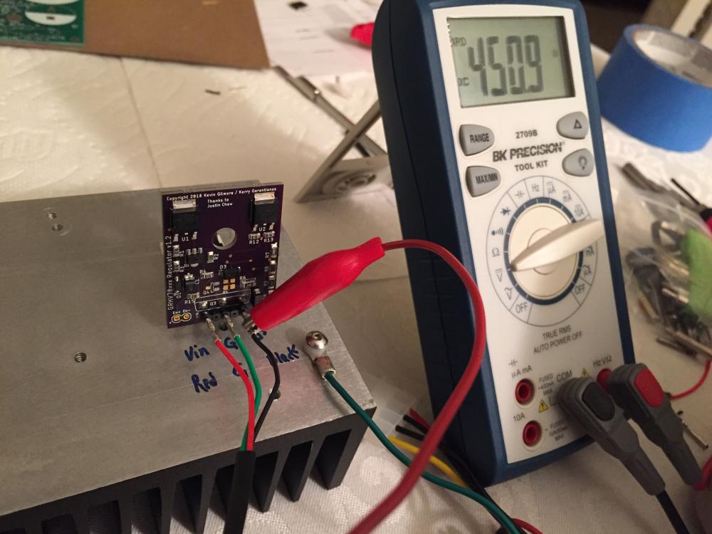
 1 point


Important Information
By using this site, you agree to our Terms of Use.