Leaderboard
-
Knuckledragger
High Rollers13Points16413Posts -
mikeymad
High Rollers13Points13709Posts -
Voltron
High Rollers13Points34512Posts -
Grahame
High Rollers9Points16720Posts


Popular Content
Showing content with the highest reputation on 07/18/23 in all areas
-
4 points
-
One of the neat things about living in such a famous place is that people do things like jump in a small airplane, fly around and photograph the town with a fisheye lens:3 points
-
I see this meme pop up reasonably often, often in non-audio spaces. I knew I recognized the center photo. The guy in the image is not some unmarried audio snob with too much disposable income. It's MoT Dave Lavry, as photographed by the owner of a certain headphone site in Jude of 2009. That wasn't a typo. I have never heard a single piece of Lavry kit, so I cannot comment further. What I CAN remark on is that the amp in the photo is a is an RSA Emmeline II "Raptor." The entire image takes me back to the late 00s and reminded me of a completely biased impression I made at the time. I straight up do not trust amps where the PSU is that much better than the amp chassis. It looks weird and makes me wonder why there are so few components in the amplifier itself. I know about as much about amplifier design as I do about driving Formula 1 race cars, but it's my opinion and I'm sticking to it.3 points
-
The power supply matters so much more, and is so much harder to design. Amp circuits are a dime a dozen - they all more or less sound the same.2 points
-
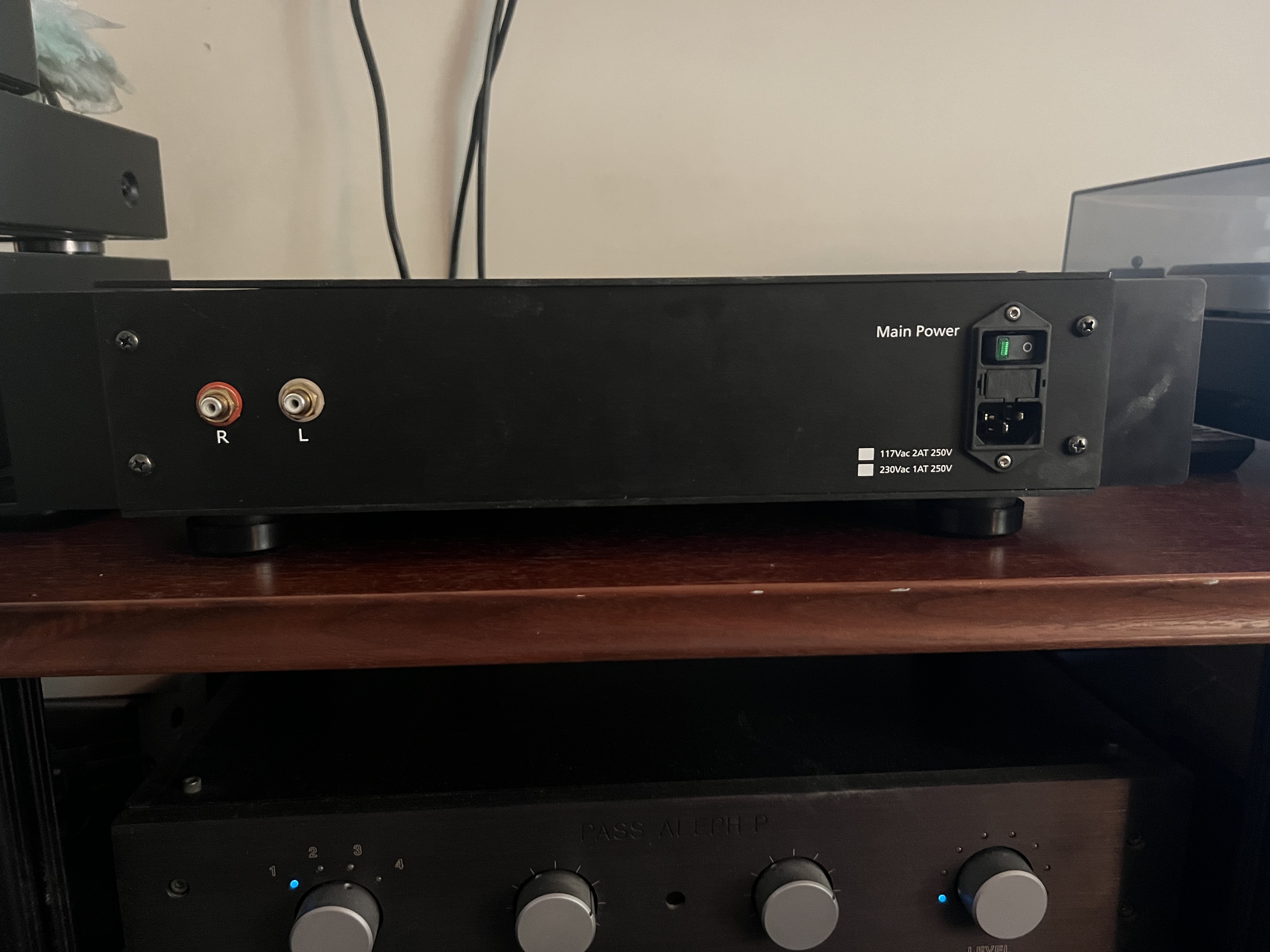
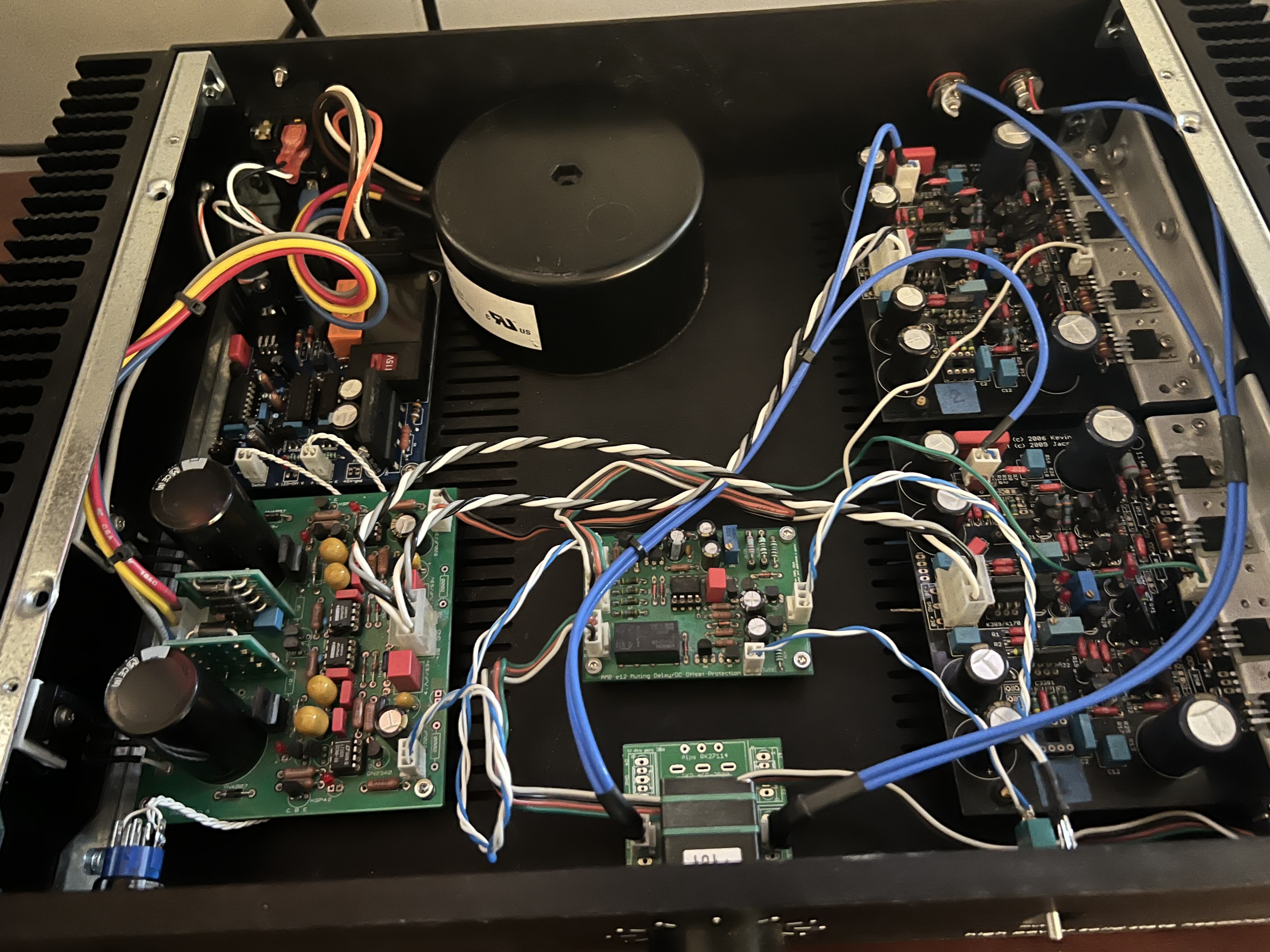
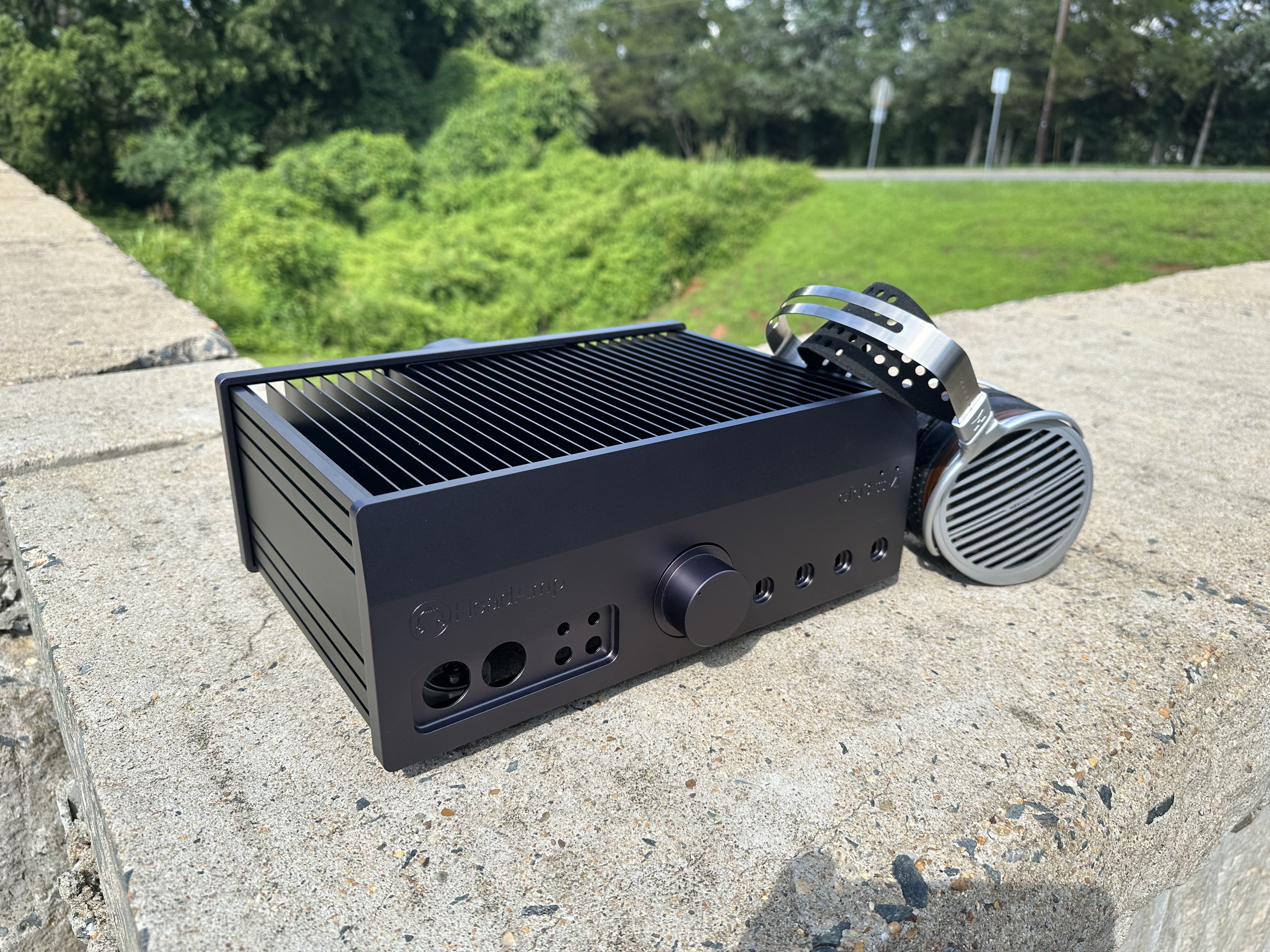
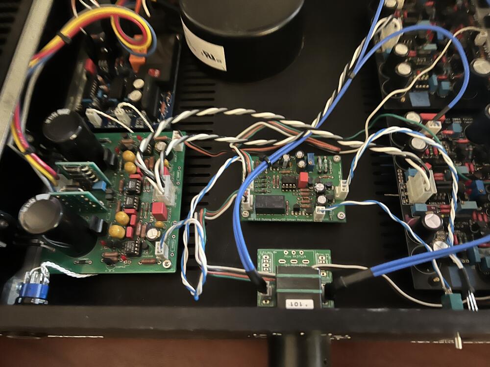
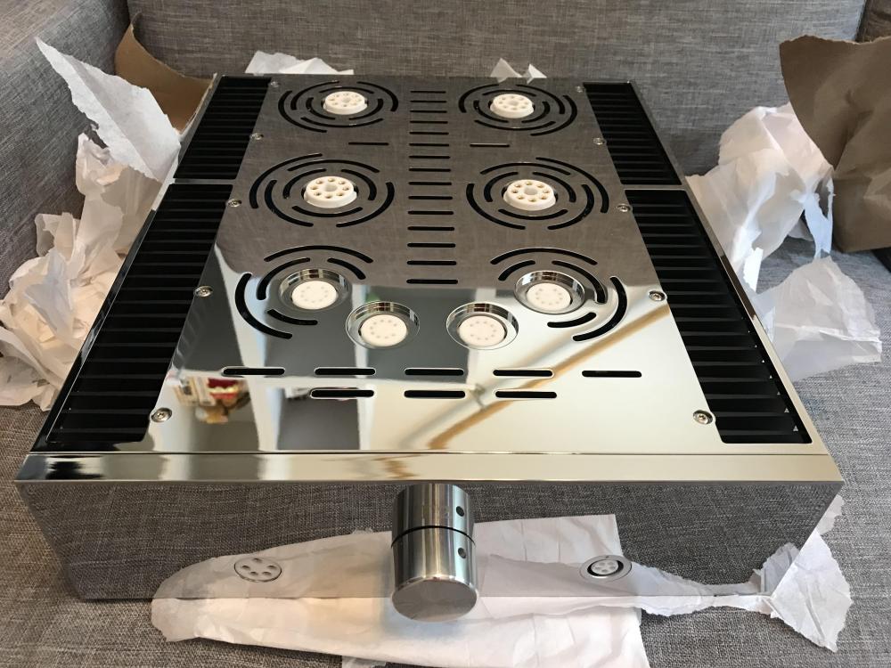
2 pointsFinally got around to casing this (also posted in the What are you building thread. Needs a bit of wiring cleanup, and the transformer needs to get bolted down, but sounds great.


 2 points
 -
1 point
-
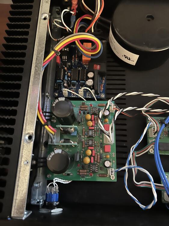
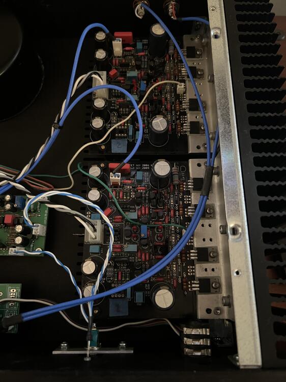
1 pointif the +-12V rails work (with no load some voltage regulators will not regulate properly and most have current and thermal limiters built in) then its highly unlikely the 7812 or 1912 voltage regulators are shorted to ground. with no load I don't see why a working psu cannot be run without heatsinks for short periods of time... however if you have a short on the output side of a HV rail then the pass mosfet/transistor could be trying to output a lot of current and be running hot even with a heatsink... if you have a thermal probe you could CAREFULLY measure the temperatures of the heatsink transistors and see if any are getting excessively hot. when the psu has fully discharged you could run your multimeter in diode check mode on each of the diodes in the psu (both directions). I assume your negative HV rail is working ok. If your psu is symmetrical then the negative HV rail is basically exactly the same as the positive rail in basic topology then you can start making comparative tests between the two. (for my T2 build I did not use the same pcbs or psu as you have so I don't have any direct experience of your psu)1 point
-
1 pointI agree that metal chassis should connect to the earth ground from the power cord/line input module. In general, I also connect the transformer electrostatic shield ground and the DC power supply ground (which is electrically connected to the amplifier's signal ground) to the chassis/earth ground. That seems to give me the lowest measured hum level. Sometimes grounding the input signal ground at the connector entry point to the chassis works best for me, but YMMV. In terms of DIY T2, since its in two separate chassis, the only way to ground the amp chassis is through the power supply ground wires in the umbilical cords. The center standoff near the back on the PSU board becomes the most convenient star-ground point. The wires going to the grounding point should be as short as possible and stay clear of the transformer leakage flux. Unfortunately that's not easy to do in the DIY T2 PSU chassis.1 point
-
1 pointMy Stax builds have always had the signal ground completely isolated from the chassis/protective ground - which is connected to the earth pin of the mains plug. amp chassis is earth grounded via a lead going to a star grounding point in the psu chassis - which is where the psu chassis and mains earth meet.1 point
-
1 point
-
It's of course a different DAC world now, but a DA10 is still in my speaker rig and I fondly remember the Lavry-Benchmark-Grace DAC battles.1 point
-
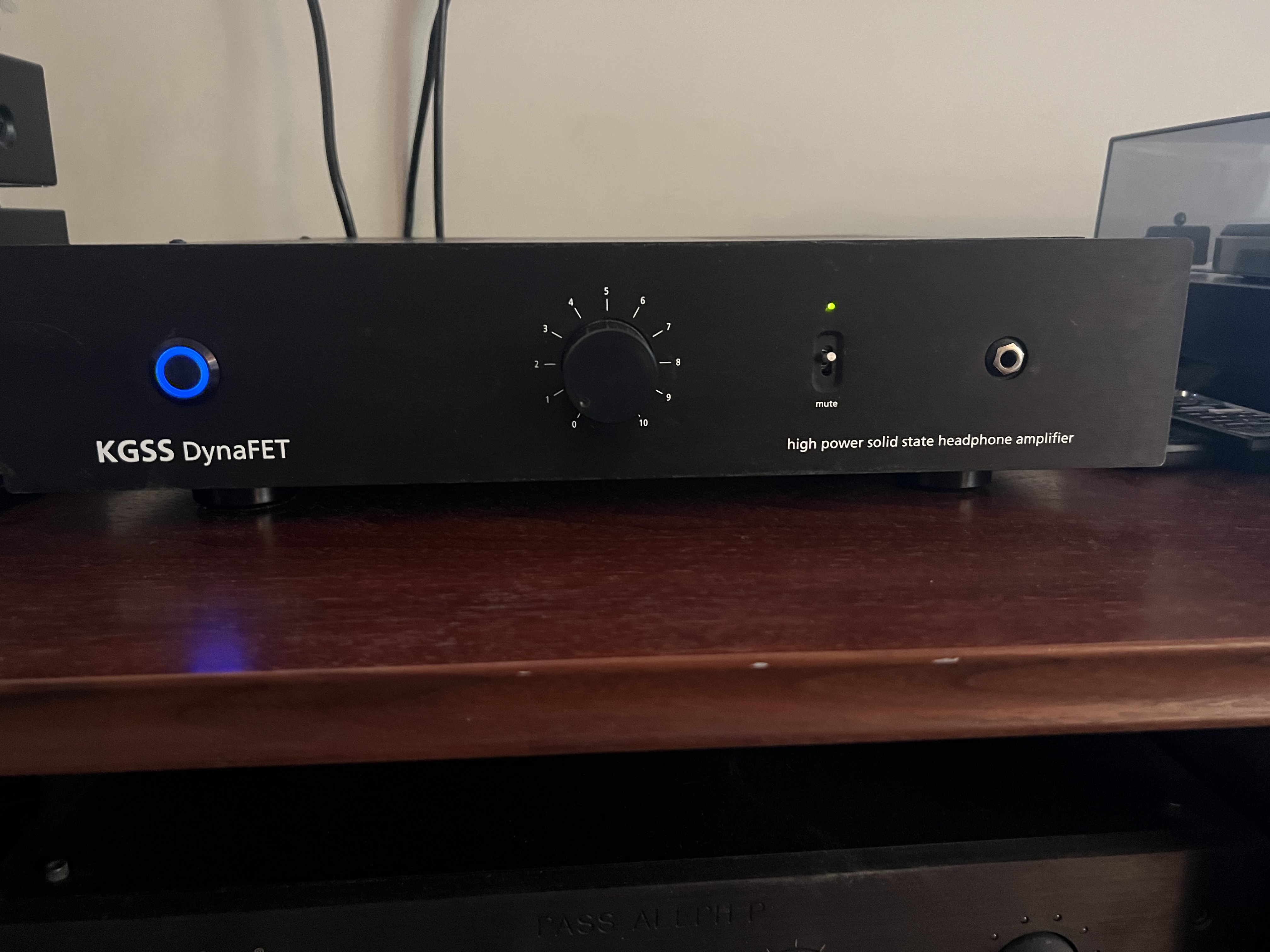
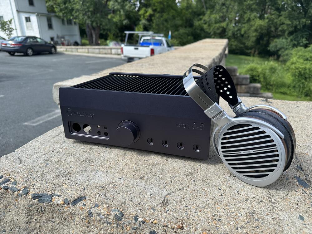
1 pointFInally got around to casing my DynaFET. I ordered the case from Modushop in November of 2021. I will probably clean up the wiring, particularly the output wiring. Also need to bolt the transformer down. I wish I would have done the lettering a bit smaller, but overall satisfied with how it turned out, and it sounds great, even though it is single-ended.


 1 point
 -
First 2 chassis just arrived. Getting it tested!
 1 point
 -
1 pointMeeting with Purk and his friend, Wut. Unfortunately, nothing new to show to them. But, as usual, we went out for a lunch together, and I had to make sure that I fed them enough. 😆
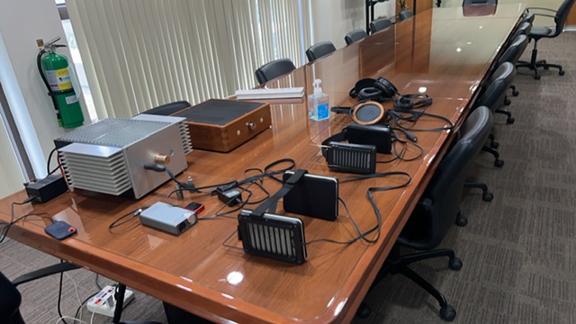

 1 point
 -
1 pointGood news, everything appears to be working normally now. With some help from georgep and joamat I managed to track down what seems to have been the culprit: one dead 2SC3675 in one of the triplets of 2SC3675's. Probably the reason two of the LEDs nearby were dead too. I just need to plug in some stax now and have a listen... All batteries now measure +200V/-539V, and R42 measures 6.55V just as it should.
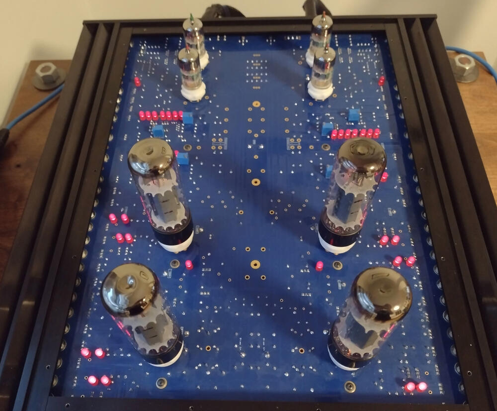 1 point
 -
1 point
-
1 pointSanta came much earlier this year!!! Thank you so much, Kerr.. I mean, Santa! ?
 1 point