

Leaderboard
-
Grahame
High Rollers11Points16720Posts -
morphsci
High Rollers9Points13301Posts -
Knuckledragger
High Rollers8Points16413Posts -
dsavitsk
High Rollers7Points4955Posts


Popular Content
Showing content with the highest reputation on 08/12/23 in all areas
-
5 pointsI enjoy rum above other spirits and there was a surprising rum tasting / dinner thingy. Sooooo poorly attended that me and my older son basically sat at a table with three ladies that work in the industry...learned a lot from them and also the head chef only had us to deal with...LOL. Odd but delicious experience. HS


 5 points
 -
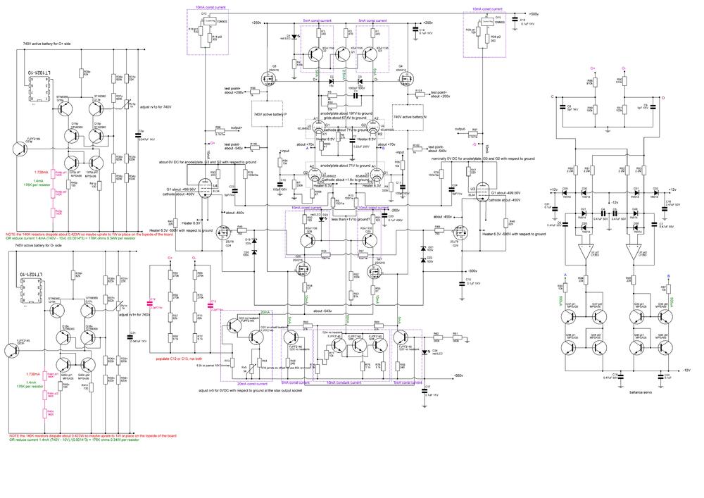
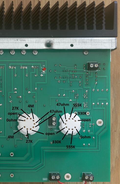
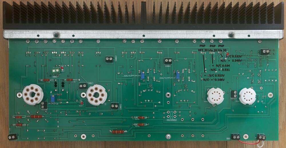
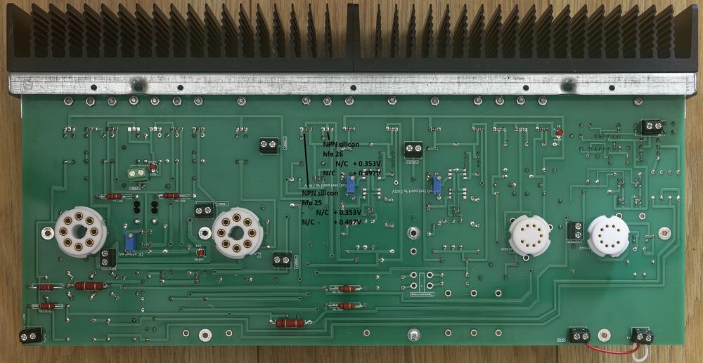
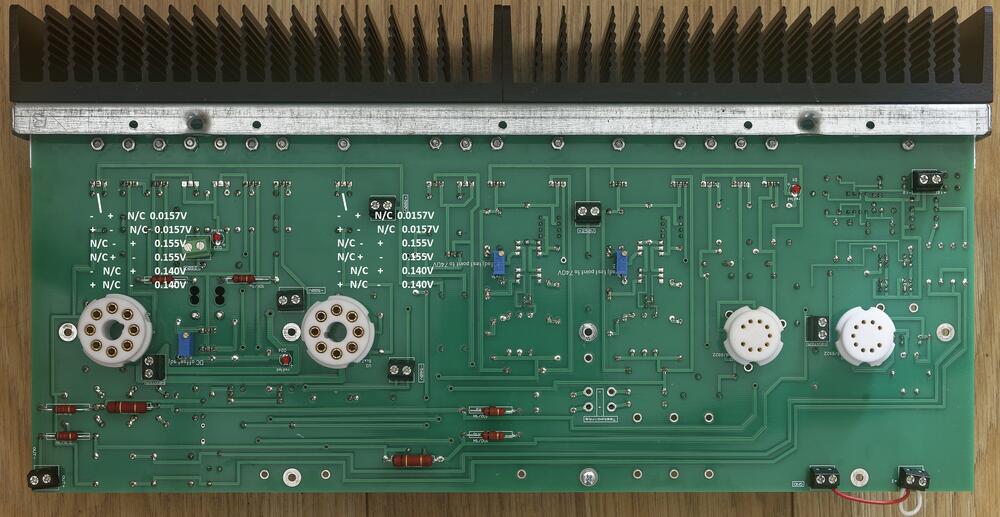
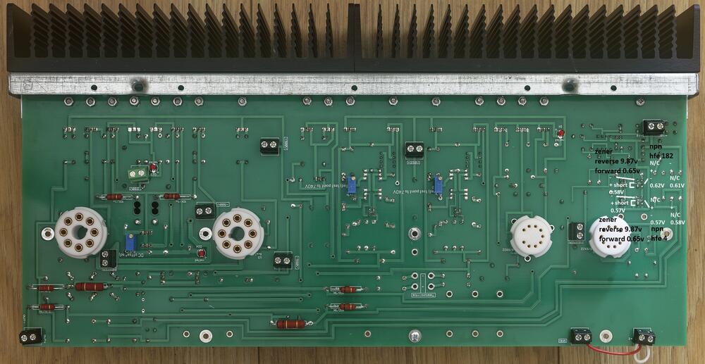
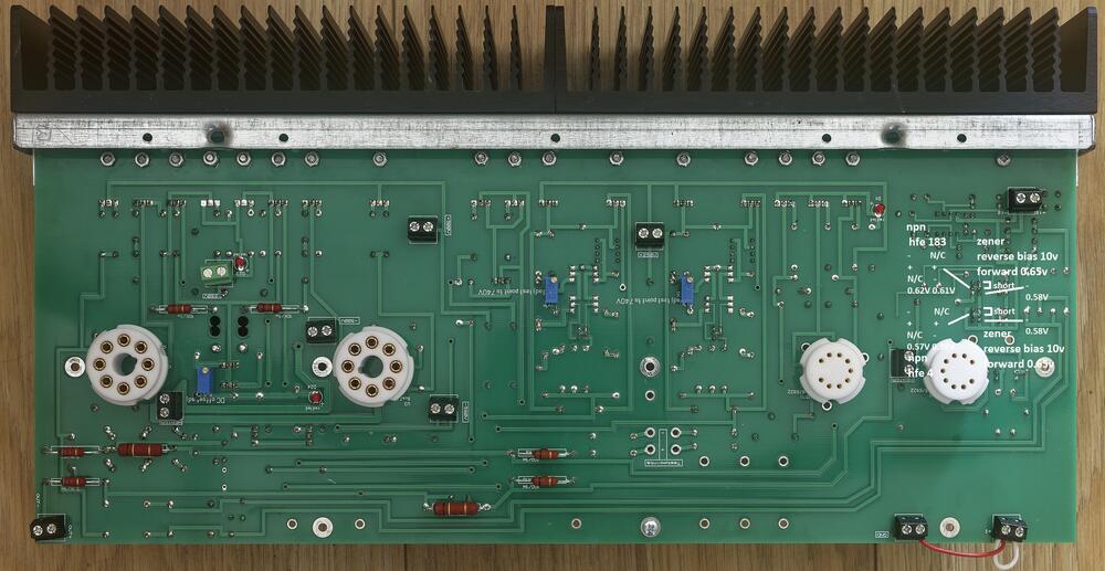
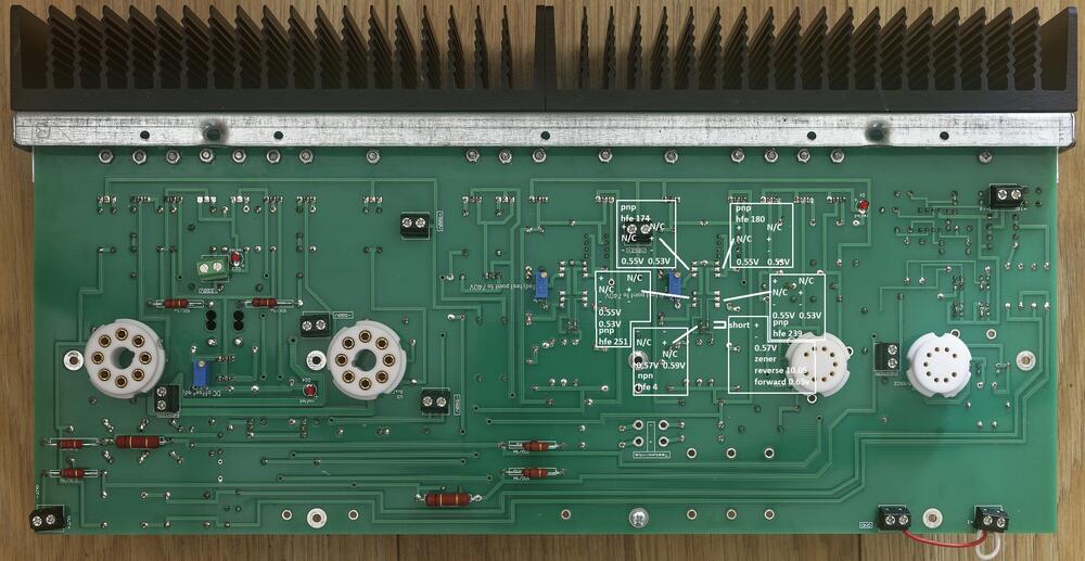
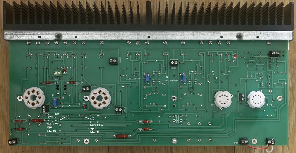
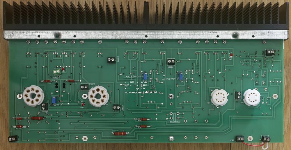
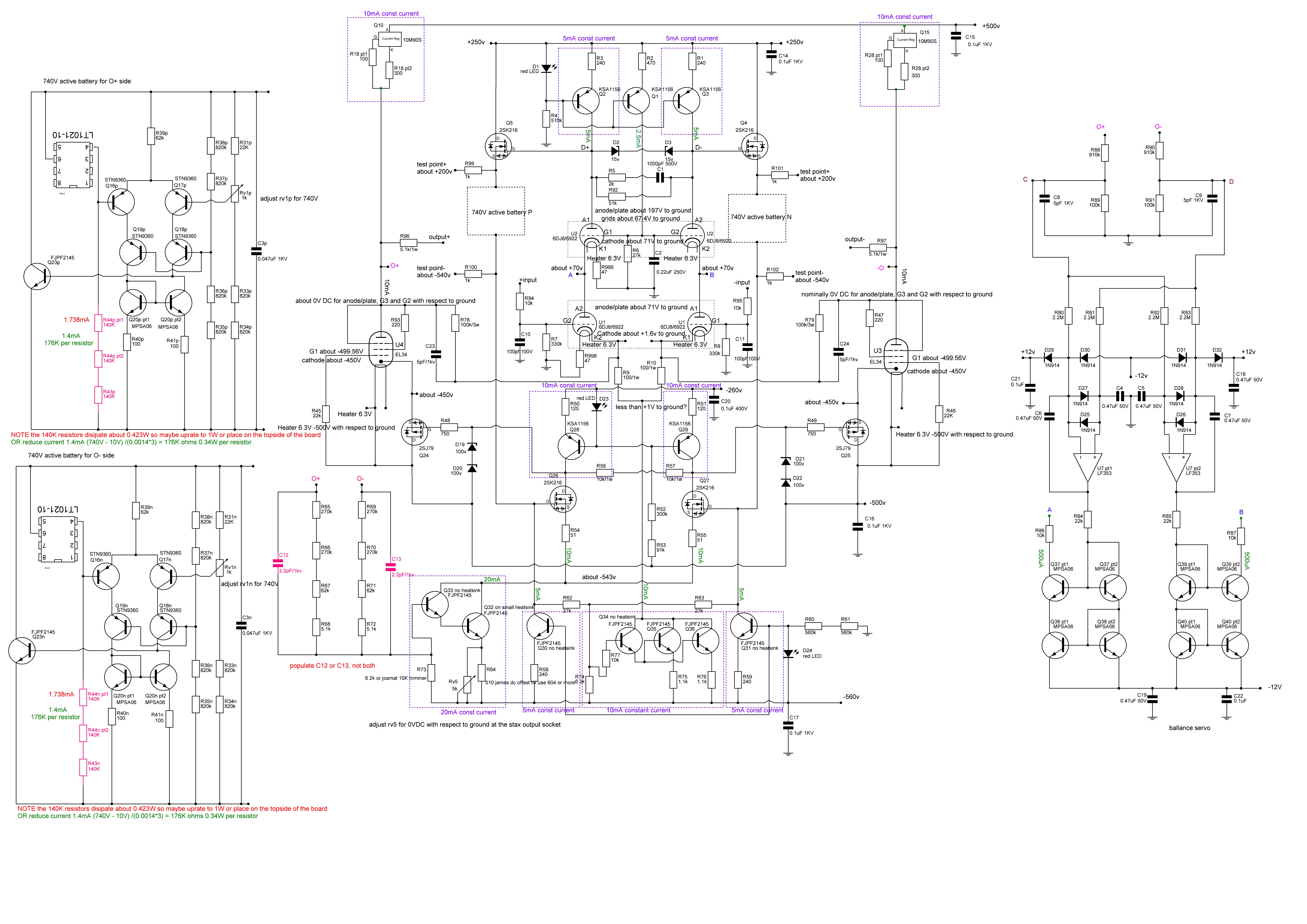
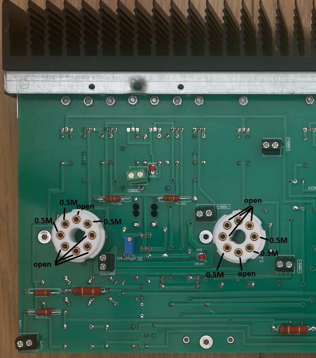
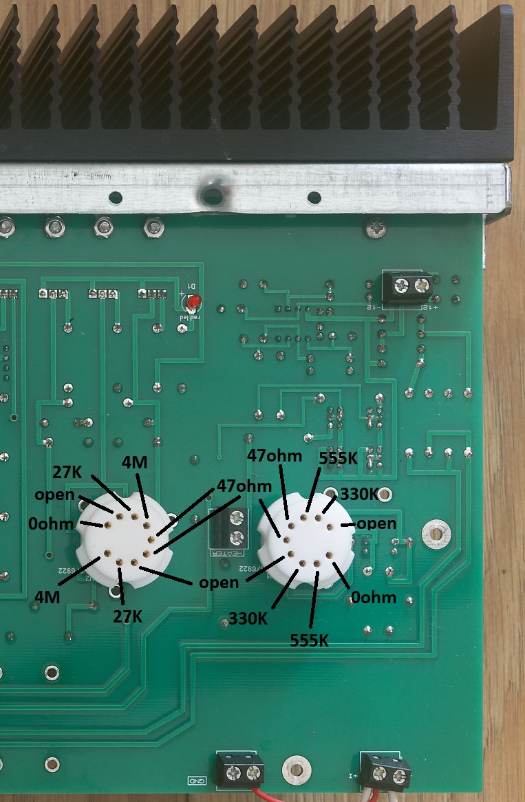
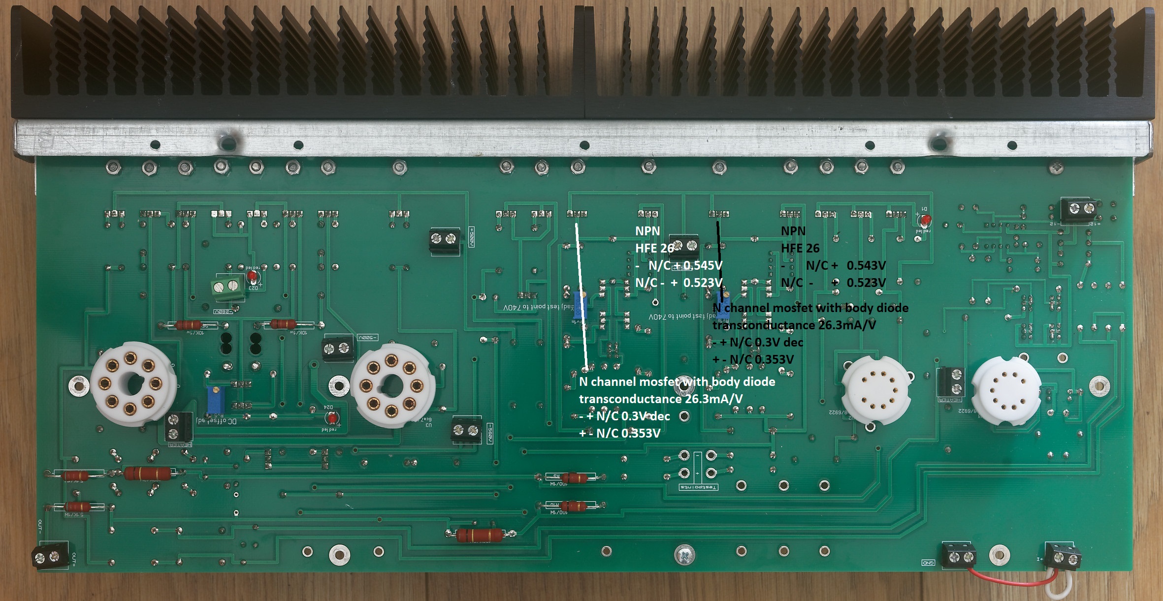
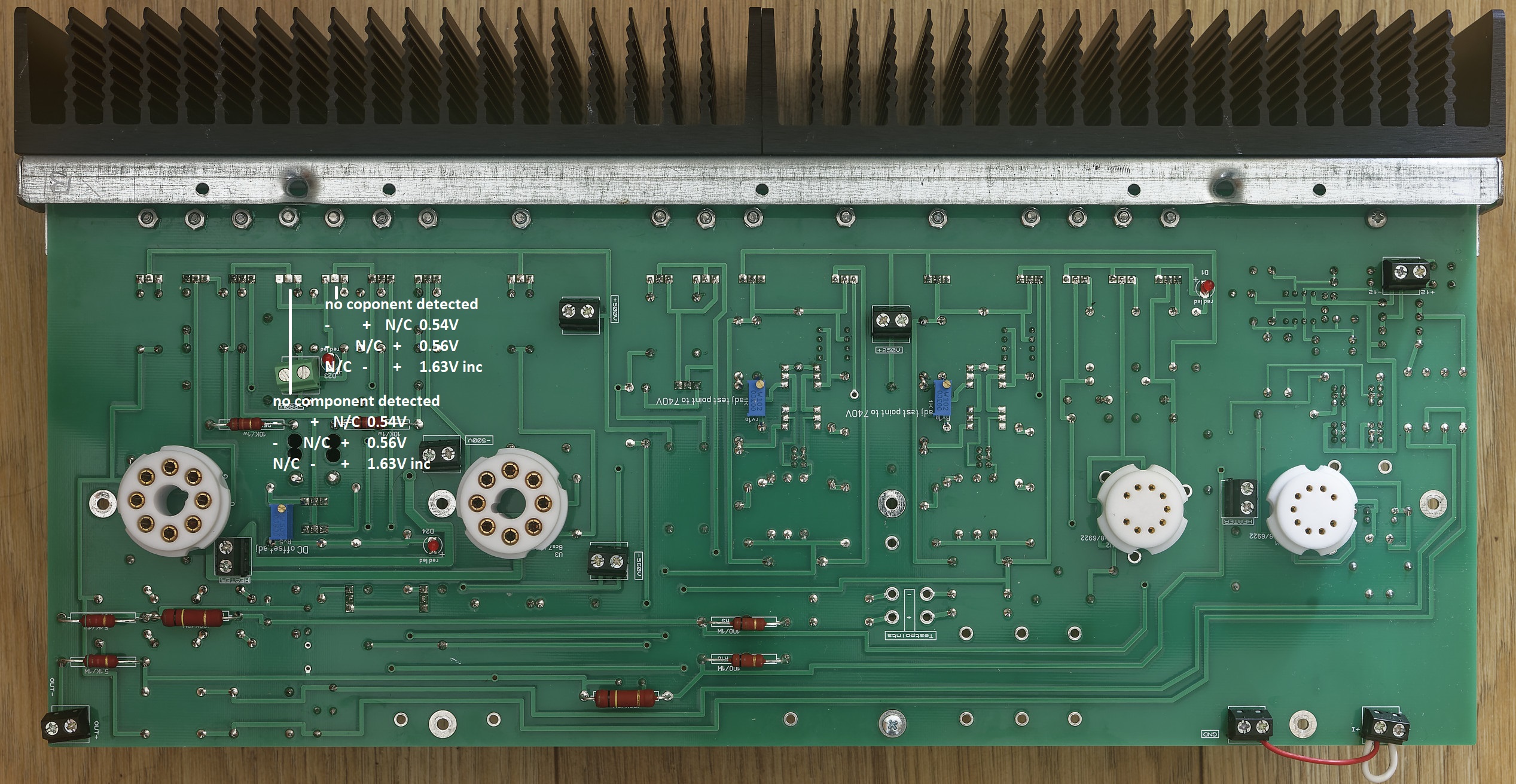
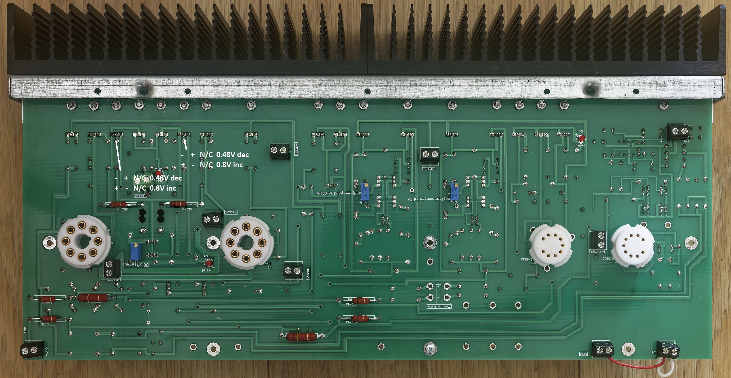
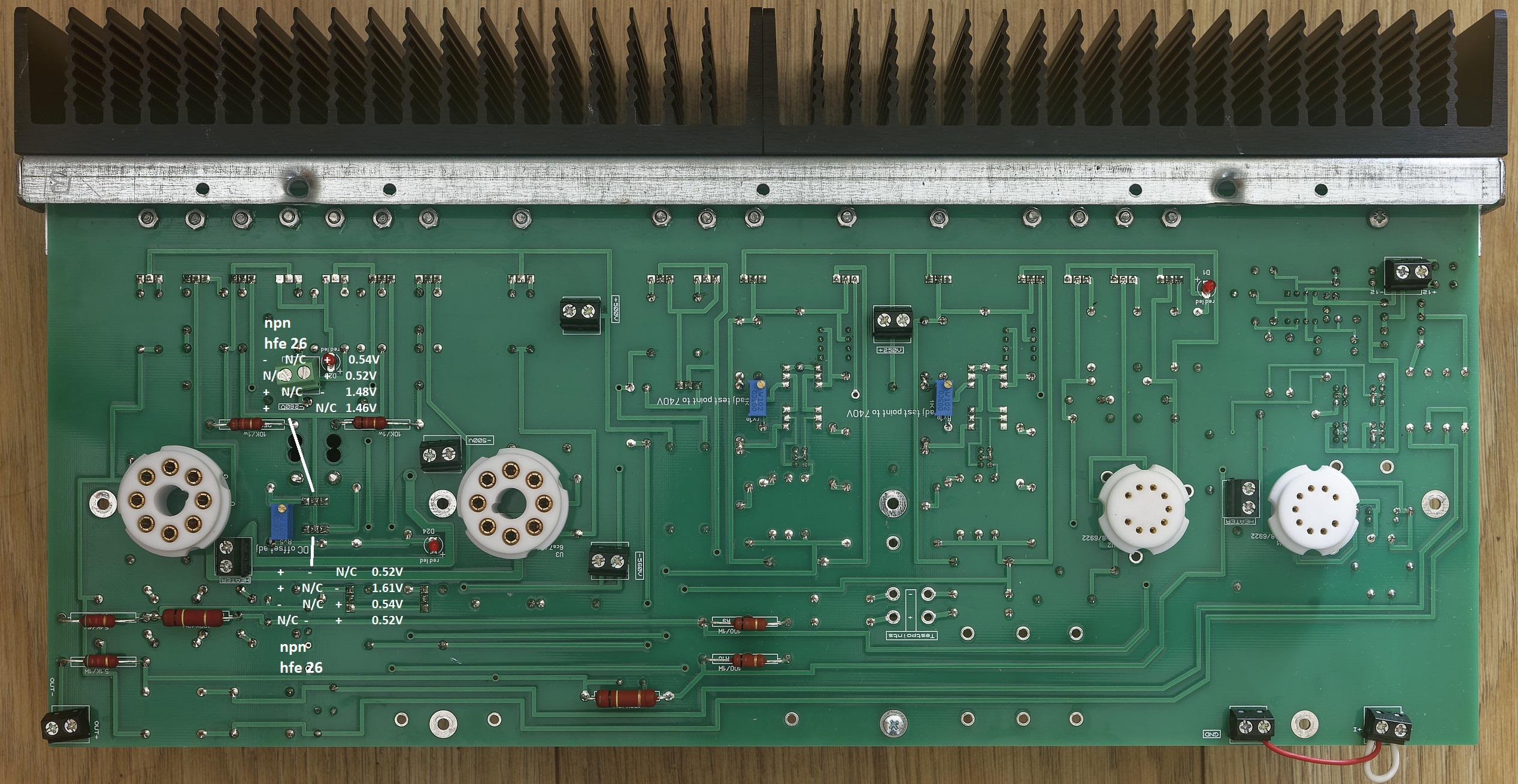
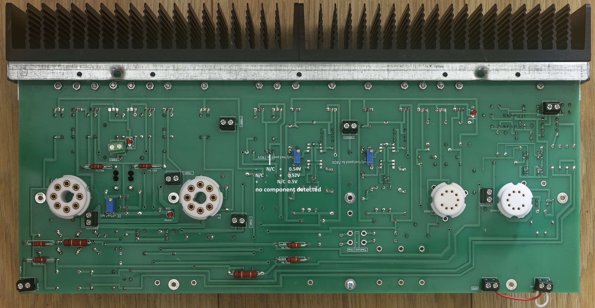
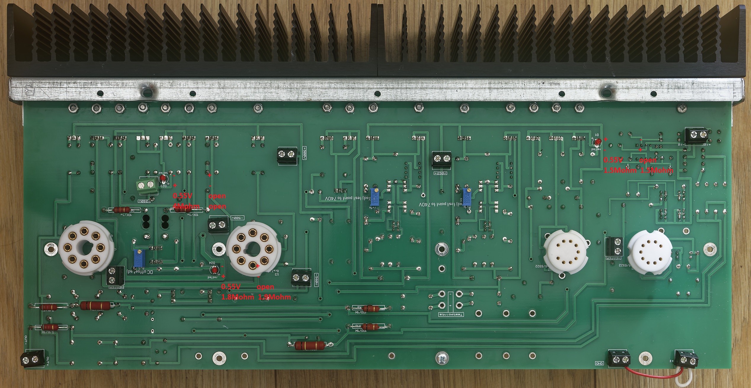
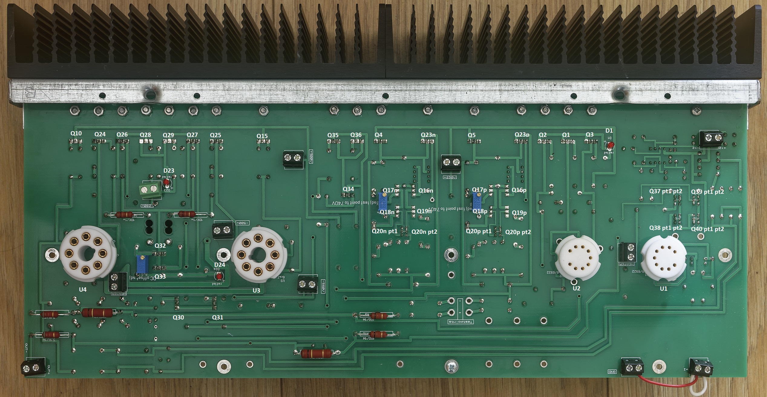
5 pointsThe unofficial mostly modern T2 troubleshooting and verification guide. Weclome, this guide covers the mostly modern T2 which has the following schematic: The gerbers for the amp can be found here: https://drive.google.com/drive/folders/1r3g2TAtBUaBdiMorTWX7yYgeJ7maQbYW and the gerbers are staxt2nc3fdh7.zip The guide is intended for both pre-power on verification of an amp build, verification of voltages on power on and general troubleshooting. All tests are performed using a Brymen BM869s and peak DCA75. Using a different multimeter may effect the results slightly but you should still get similar behaviours and ball-park figures. Transistor and Diode Location Section 1. Build verification with no valves installed and no wires/volume control connected to the amp All of these checks can be performed with a multimeter from the top side of the amp board leds Checks. All 3 leds on each channel should read about 0.55V voltage drop in forward bias (multimeter + terminal/red lead connected to led + and multimeter - terminal black lead connected to led -) and open circuit in reverse bias (swap the probes around) when tested with a multimeter in diode check mode. The leds will not light from the diode test due t the current draw if the components around them. The exact forward voltage drop will depend upon the characteristics of the red led but anything significantly different here indicates a problem. 0 voltage drop in both directions indicates a short across the led or the components it connected to. check for solder bridges and failed short transistors. 0L indicates in both directions means the led has dry solder joints or is blown. using a multimeter in resistance mode check the leds D23 close to the -360VDC psu input. In forward bias expect around 4M ohms. With the probes reversed you should get open circuit. D24 is the led closest to the octal socket for the EL34 and should read about 1.8M in forward bias and about 1.9M in reverse. D1 is between in the 9 pin sockets but close to the heatsinks. This should read about 1.5M in both directions. Readings in both directions of a few hundred K ohms or lower indicate the led may have been leaky or a transistor it is connected to has gone short circuit or a solder bridge. Input terminal checks With the multimeter in resistance mode and the - terminal connected to the amp ground, and the positive terminal connected to the + input of the amp you should get about 340K and the same for the - input. Naturally expect the same results for the other channel. If significantly different suspect incorrect resistors for R94, R7 (positive input). Or R95, R8 on the - input. Output terminal checks With the multimeter in resistance mode and the - terminal connected to the amp ground, and the positive terminal connected to the + output of the amp you should get about 0.5M and the same for the - output. Naturally expect the same results for the other channel. Valve Socket Checks. With the multimeter in resistance mode and the - terminal connected to the amp ground, and the positive terminal expect the following resistances for both EL34s: (socket viewed from the top of the amp). (note the 0.5M reading may start lower and quickly ram up and the small capacitors in the circuit are charged by the multimeter). For the 6922s (socket viewed from the top of the amp) Diode Checks of transistors Note it is possible for a transistor to fail in such a way it has very little gain but still has a diode drop and so diode checking transistors is not a foolproof measure of a transistors health. But 0V drop when not expected indicates a short etc. Diode checks KSA1156 checks Q1, Q2, Q3 two of the ksa1156s (Q2 and A3) measure the same in diode mode the centre one (Q1) differs slightly. All combinations of probes and pins on a transistor result in open circuit unless otherwise shown otherwise: + indicates positive multimeter probe attached, - indicates negative multimeter probe attached n/c indicates no probe attachment. Note: for the other channel EACH KSA1156 is rotated 180 degrees about the y (vertical) axis. Peak DCA in circuit testing Q1-3 The peak DCA 75 identifies all 3 transistors as PNP silicon. The centre with a hfe or around 28 and the other two with slightly higher hfe of 30 to 31. This test is reliable, anything significantly different indicates a problem. Note it is easier to do these tests from the underside although you can hook up the dca proe hooks to something like a sensepeek weighted self standing spring loaded probe tip assembly and test easily from the top (https://sensepeek.com/pcbite-20 Diode check and Peak DCA 75 for Q23P FJPF2145 This is reliably identified as a NPN with hfe 26 and is part of the virtual battery connected to the + output side of the channel. NOTE: It has a mirror image pinout compared to the ksa1156s. Diode check and peak DCA 75 check for Q5 2SK216 This is reliably identified as a N channel mosfet with body diode and has a transconductance of 23.3mA/V. Although not part of the virtual battery it is directly connected to it. WANRING This transistor has a live mounting tab and must be fully insulated from the heatsink. A resistance check from the metal tab to the heatsink it is mounted on absolutely must read open circuit. Diode measurement for this transistor does not show a stable reading. In this case dec indicates a reading that decreases over time. The next two transistors in the heatsink row are Q23N and Q4 which perform exactly the same role and are exactly the same type of transistors as Q23P and Q5 respectively and should measure about the same I got 28mA/V for the Q4 so expect a little variance here). NOTE: on the other channel the order of the 2SK216 and FJPF2145 are reversed. Diode check and peak DCA 75 check for Q35 and Q36 FJPF2145 These are the current providers (driven by Q34) for a 10mA constant current source that feeds the input 6922s. The job is equally divided between them and they should measure the same. The DCA75 reliably identifies them as NPN silicon hfe 25-26 Diode check and peak DCA 75 check for Q15 and Q10 (10M90S) These are identified out of circuit by the dca75 as N channel depletion mosfets. However, in this circuit they provide anode current and are wired in such a way the DCA75 can not identify them and reports no component. The DCA75 should not report any shorts and the metal mounting tab is live and absolutely must be insulated from the heatsink they are mounted on. Q15 and Q10 are identically configured and should measure the same. The gate and cathodes are connected together with resistors totalling only 400ohms so the diode drop voltages will be lower than for the other transistors also unlike the other transistors all combination of probes will result in a voltage drop. The voltage drop should be the same in the forward and reverse directions. Diode check and peak DCA 75 check for Q28 and Q29 (KSA1156) These are identified out of circuit by the dca75 as PNP silicon. However in this circuit they are wired in such a way the DCA75 can not identify them and reports no component. Each should measure the same. Diode check and peak DCA 75 check for Q26 and Q27 (2SK216) These transistors do not produce stable diode voltage drops. Diode check and peak DCA 75 check for Q25 and Q24 (2SJ79) These transistors are not easy to get a stable reading on. Diode and peak dca75 Check Balance servo Q37 - Q40 (MPSA06) 4 of the MPSA06es have their collectors and bases shorted together and so can be considered to only have two pins as far as diode checking concerned. NOTE for any transistor with shorted pins only two dca75 probes were used (one to the shorted pins and the other to the non shorted pin) to avoid the dca just reporting probes shorted. Understandably ni this case the dca75 can not identify the component as a transistor and instead reports a 9.87V zener. All other transistors are correctly identified and hfe provided. Diode and peak dca75 Check Virtual Battery Q16 - Q18 (STN9360) and Q20 (MPSA06) the other virtual battery in the channel (just to the left) should measure similarly and is identically laid out. Q20 pt 1 has collector and base shorted. All 4 stn9360 should diode measure similarly. NOTE for any transistor with shorted pins only two dca75 probes were used (one to the shorted pins and the other to the non shorted pin) to avoid the dca just reporting probes shorted. Understandably ni this case the dca75 can not identify the component as a transistor and instead reports a 10V zener. All other transistors are correctly identified and hfe provided. The stn9360 are pnp and the remaining non shorted mpsa06 as npn Diode and peak dca75 check Q30 and Q31 (FJPF2145) Each transistor provides a separate 5mA current source and are directly connected to the virtual battery. With the led D24 across their base and emitter. Each is identically configured and should read the same. Dca75 reliably identifies both transistors as npn both hfe 18 Diode and peak dca75 check Q32 (on seperate small heatsink) and Q33 (FJPF2145) this forms a 20mA current source which is controlled by Rv5 and sets the DC offset. DCA75 reliably identifies both transistors as npn both with hfe 26 Diode and peak dca75 check Q34 (FJPF2145) Q34 provides control for Q35 and Q36 which creates a 10mA current source. The dca75 says no component detected. <<< IN PROGRESS >>> #include <usual_disclaimer.h> #include <usual_high voltage_warnings.h>


 5 points
 -
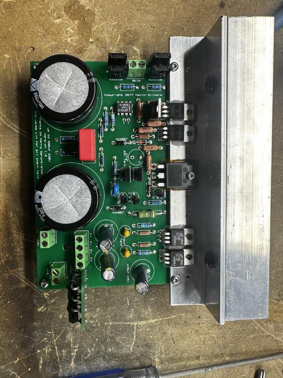
4 points1, 2, 3, 4, cretins wanna hop some more ...3 pointsIn the mood for some slowcore? Say no more: Cigarettes After Sex: It's like dreampop, except without the uplift. And maybe less reverb. @VPI-- considering you like Cowboy Junkies, you might like this.3 points2 pointsAn Eastern European dual citizen polyglot (Is there any other kind?), that could probably help 'Stretch with his pronunciation.2 pointsGrhv100 nearly ready to test, waiting on 90/8 trafo from toroidy and some shoulder washers for the to-220’s. Sink is temporary. Added discrete bridge for heaters per Dukei/miroslav, who’s built a few. Are the +- pads out from the smd relay for an LED? Warmup delay? Any details on bias/balance adjustment on the tube board? Looks like plate balance and cathode resistor trim?
 2 pointsI showed amazing restraint today. This sold for just over $400 shipped. 5D Mk II, 80K shutter activations, a pile of memory cards, SIX (5 pictured) batteries, two chargers, cables etc. Guy also had a 40mm pancake, a tripod slide mount thing and some other kit. All of his auctions ended this morning, when no one was around. I resisted bidding on any of it. I've set my sights on a 5D Mk IV and am sidestepping the alarmingly cheap 5DIIIs and 1DxIIs, no matter how tempting they might be. Tonight. Tonight there's gonna be some shit.2 points2 pointsThat curry looks amazing, Grahame! We went to a Vietnamese owned BBQ joint yesterday for lunch I'd read about. The BBQ is fairly traditional with prime brisket, ribs and jalapeño beef sausage, but the BBQ fried rice had brisket and a Chinese sausage that was a bit sweet and yummy. They also pickled their jalapeños in a soy concoction that was delish. Overall, high marks. Place is called Brisket & Rice for those that like to wander Houston... HS

 2 points1 point1 point1 point1 pointFancy nibbles! Are you with some Brits? Obviously, I didn't say other Brits given your current citizenship.1 point1 point1 pointIs it really cooking if there was no application of heat? Homemade hummus
 1 pointAnd now for something newer - Non Stop Pop (100.7 FM from GTA V):1 point1 pointWillie Nelson & Sinéad O'Connor - Don't Give Up1 point1 pointSimilar to https://www.theverge.com/2023/6/30/23780115/aspartame-iarc-who-food-safety-carcinogen My ADI is significantly below the threshold of concern. Plenty of other things to worry about, https://www.mirror.co.uk/news/health/things-more-cancerous-diet-coke-30386860 if you like to worry ("would it help?") How are your Cigars? ?1 point1 pointWhat exactly are Roger Daltrey and Pete Townsand's views on Aspartame?1 point0 pointsOne funny here, I've been working on a Stax SRM-007tA today and it is one of those long rumored units that use GE 8CG7 tubes and not the EH 6CG7's. It must have have been a fuck-it-Friday though at Stax as did they use a different heater supply for the 8.4V tubes? Nope... they jumpered the 1ohm resistors in the heater supply but it is still run off the same 12.6VCT winding, fed through a bridge and some caps. End result was a blown heater in one of the tubes as it was being run at 6V... 😂0 points0 pointsI’m terribly sad about the news coming out of Hawaii with these fires. My family has been visiting Maui nearly every year since I’ve been born and I just can’t believe that in a single windy day and night the beautiful Town of Lahaina was completely burnt to the ground. RIP to those who were lost to the fire and my sympathies to those who made it out but lost their homes and businesses.0 points


Important Information
By using this site, you agree to our Terms of Use.