

Leaderboard
-
dsavitsk
High Rollers11Points4968Posts -
guzziguy
High Rollers9Points10878Posts -
Hopstretch
High Rollers7Points16809Posts -
Wmcmanus
High Rollers5Points3517Posts




Popular Content
Showing content with the highest reputation on 05/26/16 in Posts
-
8 points
-
3 pointsI went on my first ride since last year. I went 30 miles. The first 25 were good. The last 5 were amazingly painful and slow.3 points
-
3 pointsIt has a motor and is lots of fun. I broke it about 10 years ago and fixed it on Saturday $30 for new batteries and it's ripping around almost like new. Ordered some new tires and extra wheels too. A lot cheaper at 10th scale3 points
-
2 points
-
2 points
-
2 pointsI'd eat that until the cows came home. Then I'd eat the cows. Looks amazing though. Is there braised pig cheeks or something under the egg? Veal tartare and lamb kebab for me tonight, with a negroni to start and some very tasty local grapes to round out the food groups. Really freaking good.2 points
-
2 pointsLast night at Girl and the Goat with Bryan, Allison and Debbie, these were just two of the ten wonderful dishes we had. Pig Face Pork Shank Some of the best food I've ever had. Sent from my iPhone using Tapatalk2 points
-
1 pointhttp://www.innerfidelity.com/content/canlanta-even-blind-hog-finds-acorn-now-and-again#rbZbqbGXL20ShvMv.97 Canlanta page on Innerfidelity is up folks!1 point
-
1 pointThe fabled L3 is likely going to be called the Apsara. I have built that topology in a power amp before, but the headphone amp has considerable refinements over that circuit (which is lovely nevertheless). The tube amp I had at the show was the Copenhagen which is a pentode amp. Also lovely - pentodes are underappreciated.1 point
-
1 pointOnce Brent heard "sauce" he was lost in dreams of Biscuit Gravy.....1 point
-
1 pointHe told me everything about it, including all the secret sauce. I have no idea what he meant, but he said he could never repeat it. Sorry, T$. **BRENT**1 point
-
1 point
-
1 point
-
1 point
-
1 pointTotal harmonic distortion, intermodulation distortion for example - I thought the comment on Fourier Analysis kind of gave it away.1 point
-
The EBTG posts made me pull out Baby The Stars Shine Bright, and my favorite song of theirs: EDIT: the blond woman playing piano, Cara Tivey, we think is related to my friend Steve.....1 point
-
1 pointCavs sending a message tonight. Raptors need to just shake it off and try again next time... but it will be a massive uphill battle to win in Cleveland in Game 7 if it gets that far.1 point
-
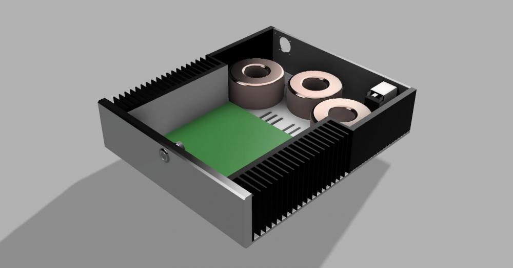
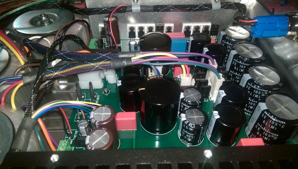
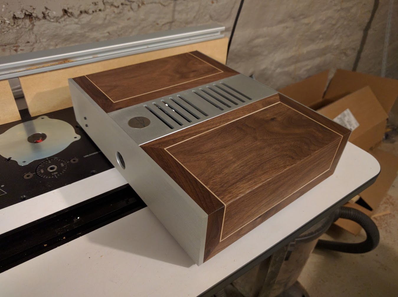
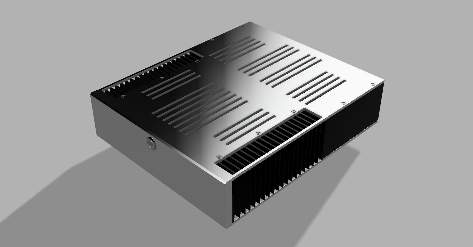
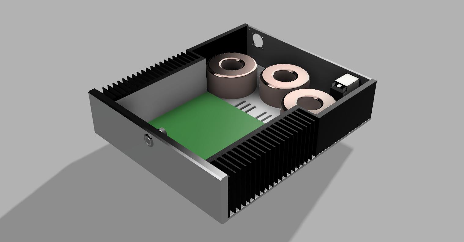
1 point1 point1 pointThanks for the comments above I do appreciate it since I'm always looking to do better. I was thinking of putting the transformers in the front, but I couldn't fit the power inlet and output comfortably with the board layout. I can think about this as a future revision. Currently, I've got about a 4" gap between the top of the transformers and bottom of the inputs when the units are stacked, which helps a bit. I've also got about 2" between the transformer and output and I will shield the output cable leading to the output. Transformers are shielded too. Additionally, I added shielding (tied to chassis/earth on the PS side) between the AC in the umbilical and the DC outputs. I can look into mu metal / steal as well. This seems like a great solution. What about a steel mesh (just thinking of air flow)? What's the specific concern on the transistor mounts? I know there are more screws if I want to remove the board, but I did like the idea of saving space and also that there was one less component between the transistor and the sinks. I considered mounting the transistors to a 3/16" flat plate and mounting the plate to the sinks, but it just felt like a lot of extra machining and I didn't have a clear goal for it in mind. EDIT: One other thought/question. I was going to solder the transformer leads for the filaments directly to the output jack. If I need to replace that transformer for any reason I could simply cut the leads and splice the new transformer in. I don't love this, but it's not that much work in the grand scheme of things just in case the LV transformer blew out in the future. Are there any good suggestions for in-line connectors? For the output filaments, they'd need to be able to handle the -500V to chassis/input filament isolation. This feels like a bit of over-engineering, but this whole build is about that :)1 point1 point1 pointi parked in the firelane and got away with it. Take THAT, society!1 point1 pointLeg of lamb steaks with homemade stout brine marinade and stout bbq sauce, potatoes and broccoli all cooked on the grill.1 point1 pointYesterday: lots of lamb Today: sweetbreads and pumpkin risotto1 point1 pointQuotes from http://physicsworld.com/cws/article/news/2013/jan/31/human-hearing-is-highly-nonlinear , originally published in Phys. Rev. Lett. 110, 044301 – Published 23 January 2013. "The information available from Fourier analysis is bound by an uncertainty relation called the Gabor limit. This says that you cannot know the timing of a sound and its frequency – or pitch – beyond a certain degree of accuracy. The more accurate the measurement of the timing of a sound, the less accurate the measurement of its pitch and vice versa." "Oppenheim and Magnasco discovered that the accuracy with which the volunteers determined pitch and timing simultaneously was usually much better, on average, than the Gabor limit. In one case, subjects beat the Gabor limit for the product of frequency and time uncertainty by a factor of 50, clearly implying their brains were using a nonlinear algorithm." In other words, conventional analysis of non-linear distortions in an audio system tell you absolutely nothing about how it sounds, because human hearing beats measurement by a healthy margin.1 point1 pointRather take them with a hefty grain of salt. The 207 and 507 sound nothing alike so something is rotten. There seems to be this movement now that measurements are king but they only tell part of the picture. Do amps sound the same based on THD, frequency response and noise? No!!1 point1 pointWorking on casing the power supply now. The first two images are renders from Fusion 360 (love this program for CAD/CAM)... I got the transformers from Richard at SumR. I added a winding to the LV transformer for the +5V I use for the control circuit/relay as well as the Arduino and digital relay. I also removed a winding on one of the HV transformers since it's not used and adjusted some voltages. Just finished testing them in the new setup and so far so good. I've still got to test everything under load before reconnecting to the amp. The face plate is a temporary while I mill the final one.

.thumb.jpg.522e13581717fa034ec8b3182eeb64cd.jpg)
.thumb.jpg.5246d485eac82e428e6894183e3808e1.jpg) 1 point1 point
1 point1 point













.jpg.3520493ce00038c8102b6833d1336d62.jpg)

.jpg.49acaffc3cdac312ba5e6b3f0608d437.jpg)

Important Information
By using this site, you agree to our Terms of Use.