

Leaderboard


Popular Content
Showing content with the highest reputation on 04/09/22 in Posts
-
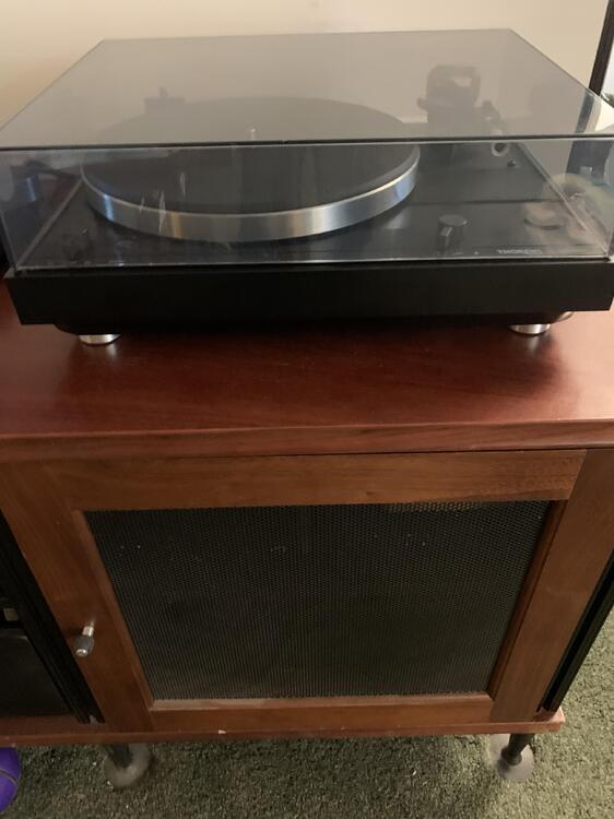
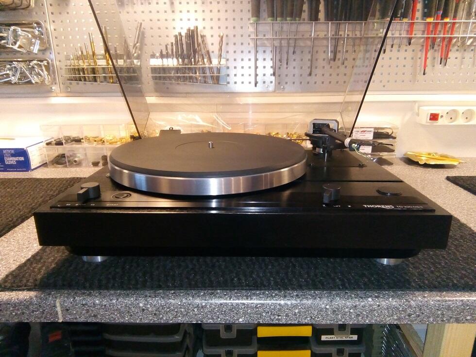
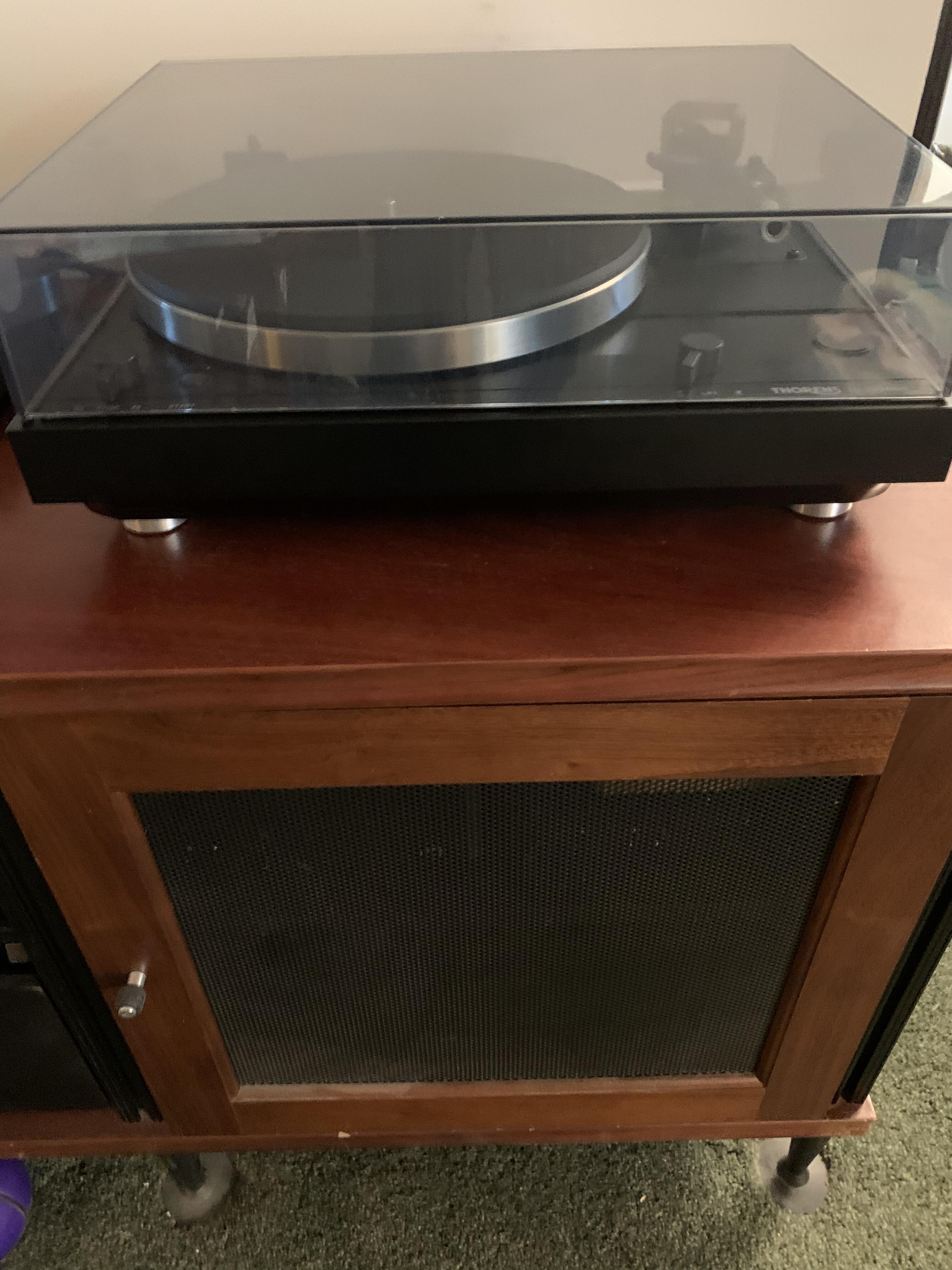
9 pointsBought a restored Thorens TD320 Mk ii from a shop in Denmark. I liked my original Mk i, but wanted the better arm. I'm installing a Grace F9e with SS stylus on it. Might not be the best match, but will see.
 9 points
 -
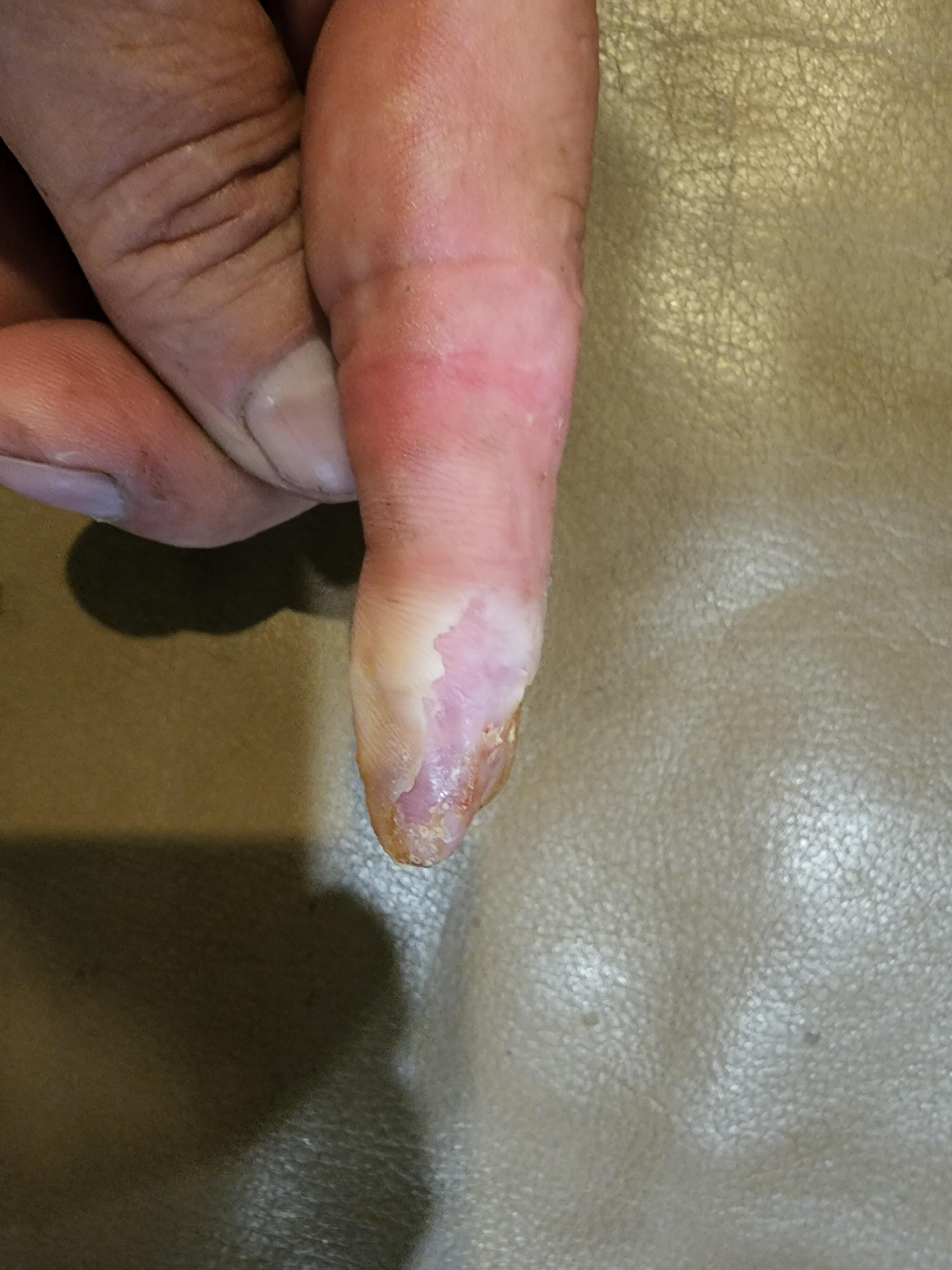
7 pointsSorry in advance to any squeamish heteros. I really don't remember how to hide photos. New skin growing in quickly. I had an eye exam yesterday at Marin Clinic. The Dr. asked why my finger was bandaged. After telling g her the story she insisted on having one of the general physicians look at it. After looking at it he said it looks like it's healing well, and said that I was doing everything right, other than not seeing a Dr. about it at the time. He commented that it was lucky it wasn't a worse outcome. I then showed him several pictures I took right after it happened. He about fell on the floor. He told me that I'm an amazing healer. That has always been the case, and I'm glad to see that age hasn't slowed down that process for me. Oh yeah, my eyes are great too.
 7 points
 -
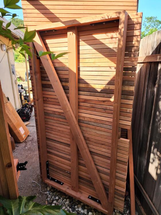
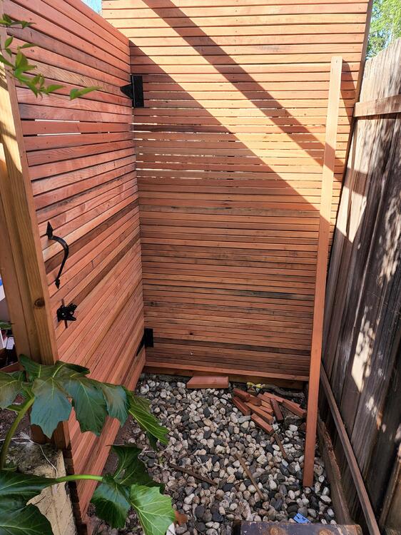
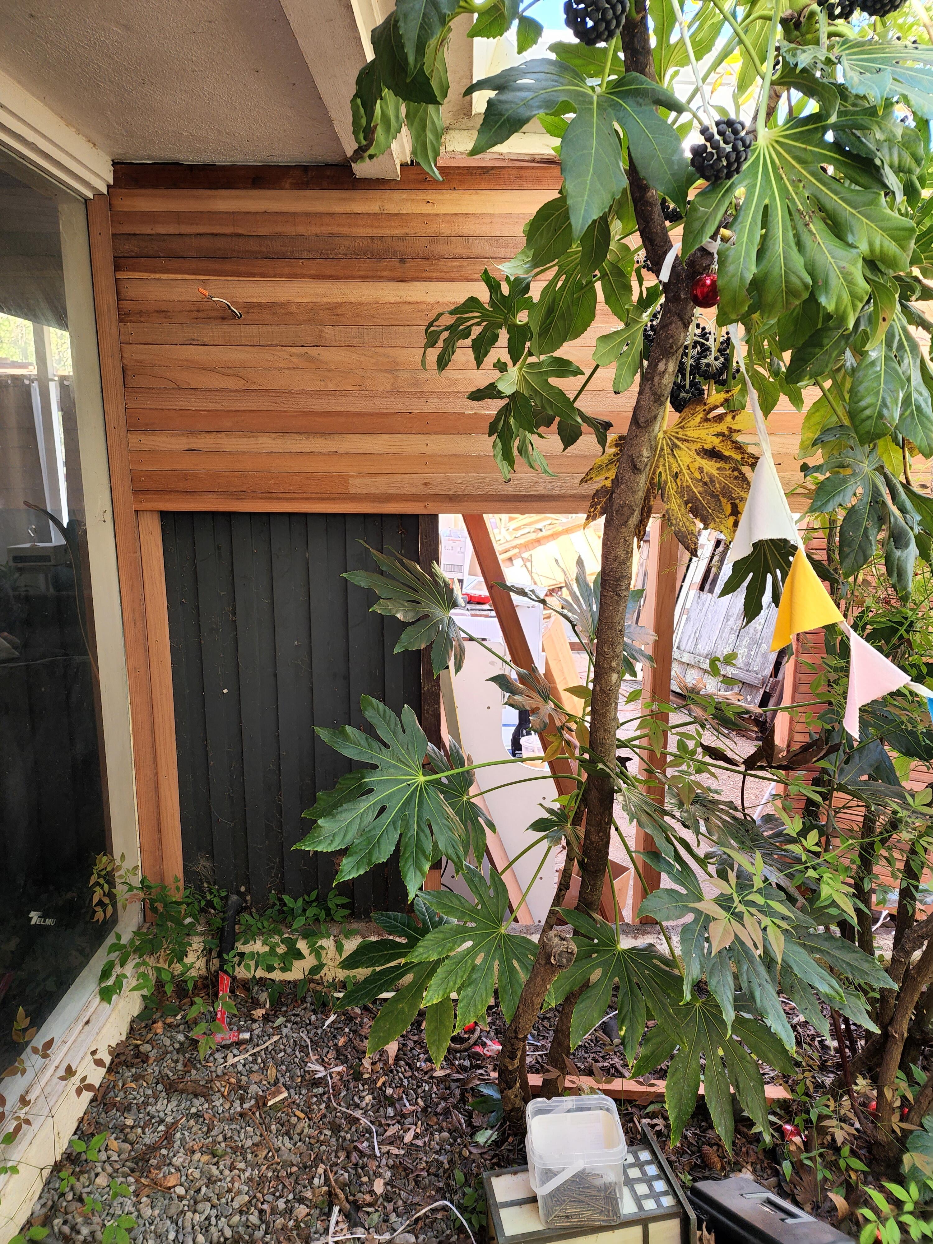
7 pointsFinished up the fence/gate job at my boss' house. The wall now reaches down to the top of the planter.
 7 points
 -
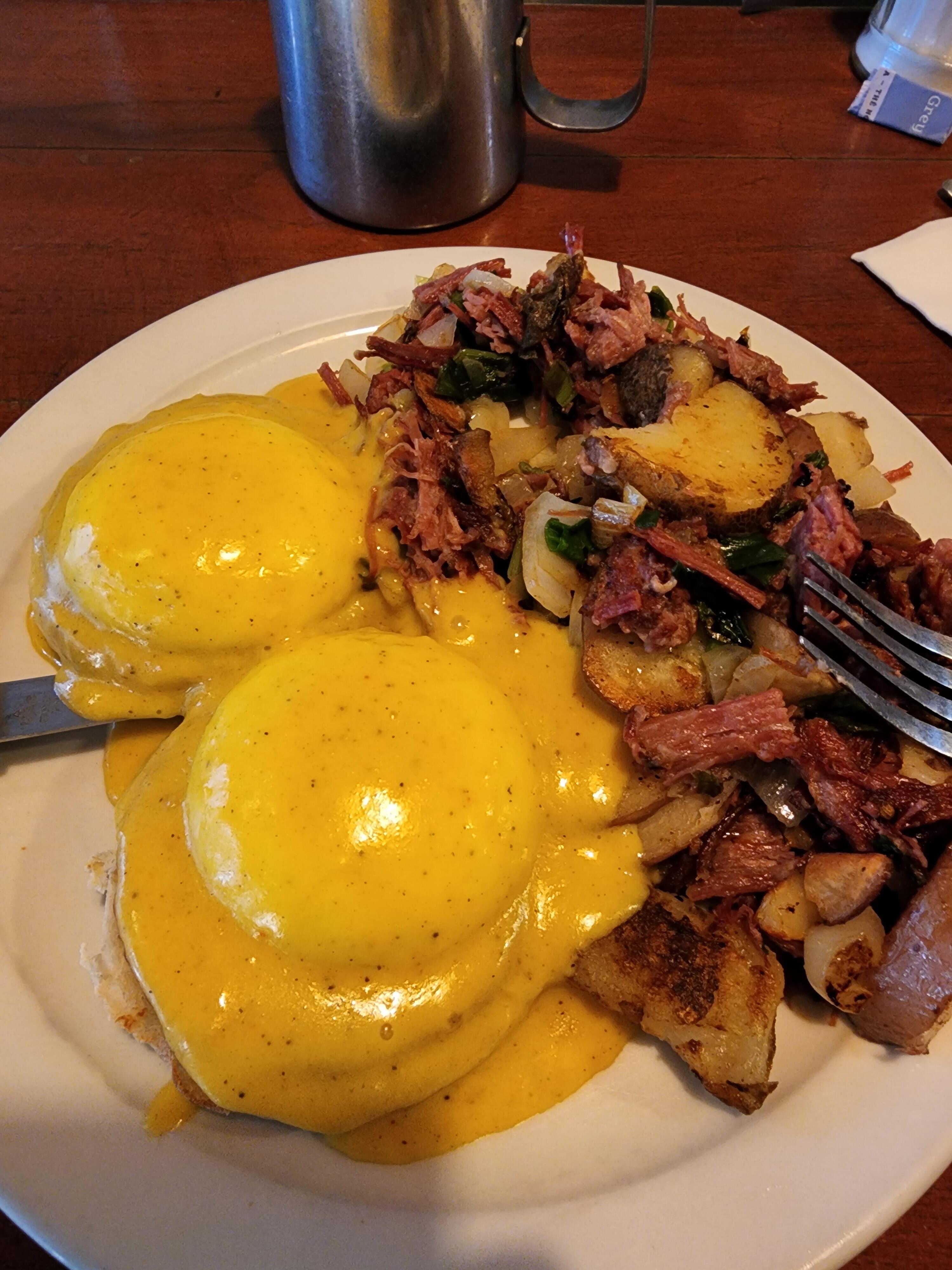
6 pointsEggs Benedict w/corned beef hash @ Lundy's in San Rafael. Delicious!
 6 points
 -
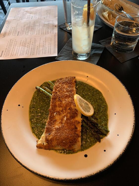
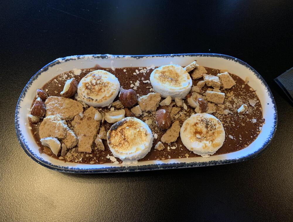
4 points4 points3 pointsLast night (and the last night before Karen returns):Started with an Arugala and Shaved Fennel Salad Followed by a Smoked Fish Dip with Tortilla Chips The Fish of the day which was a Panko crusted Flounder with Asparagus and a green sauce I did not catch And lastly a chocolate Pot de Crème with hazelnuts, marshmallows and graham cracker crumbles


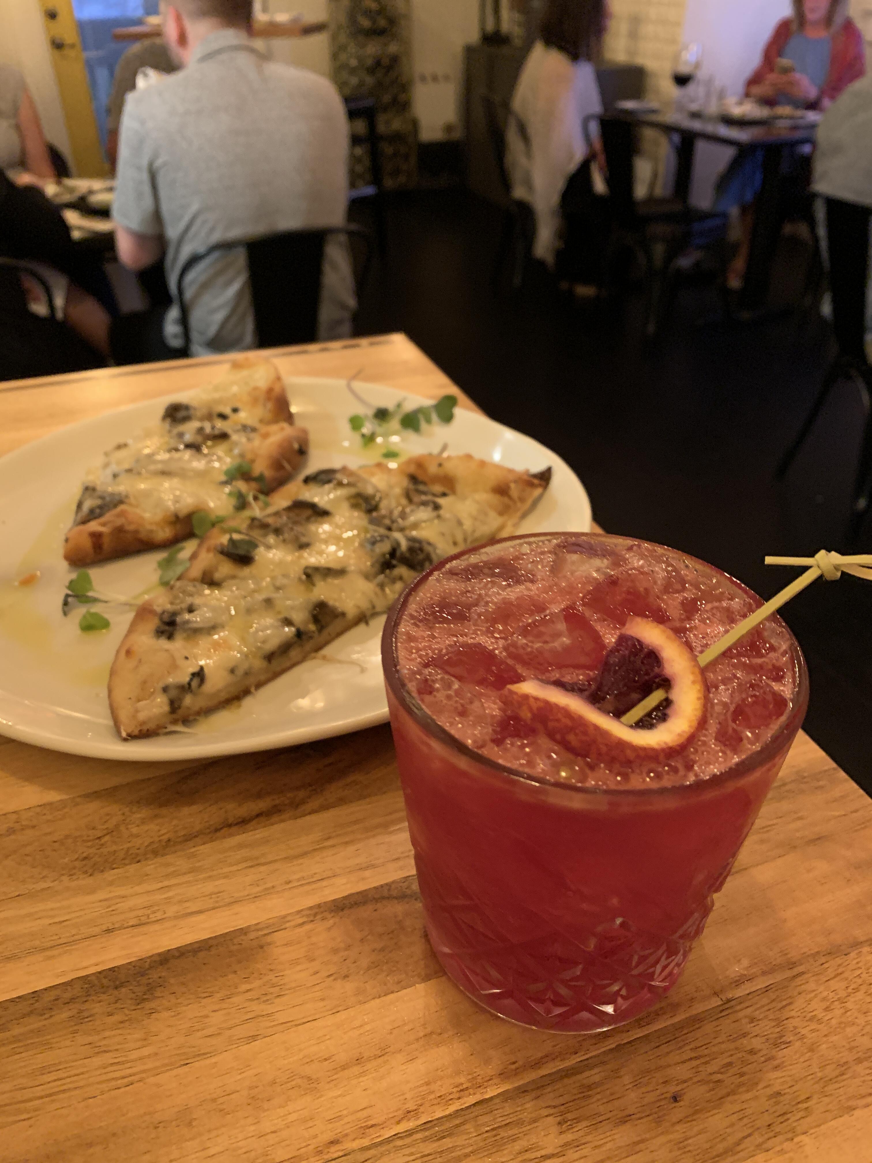
 3 points3 points3 pointsHaven’t seen. Michael Mann is executive producing a new series on HBO called Tokyo Vice. He’s also directing a few episodes, including the pilot, which I just finished. Worth checking out.3 points2 pointsBit late to the game but this little cheap guy has saved me a few blades and choice words. I've found shards of old rusted out nails with this so I think a cock ring would be easy to find. https://www.rockler.com/little-wizard-ii2 points2 pointsRecently, I became a member of the Board of Directors of the Communities of Belonging Organization. We strive to help marginalized individuals get the resources they need to persevere and re-enter society successfully. https://communitiesofbelonging.org/ As a part of April being 2nd Chance Month, we are holding a walk to raise awareness and funds to support our vision. We will be walking around Green Lake in Northern Seattle (for any locals in the area). If you would like to be a sponsor, I have setup a team on our Givebutter site. Please take a look. https://givebutter.com/XXcbAZ/michaelmaddock Please feel free to ping me with any questions and thanks for everything. Cheers, Mikey1 point1 pointthat person is a moron. the orpheus has 3 capacitor coupled stages. the BH is completely dc coupled.1 point1 pointFor actual 220VAC line voltage, feel free to move the white wire back to its former position. The rest of Europe is pushing well above 240V so that's what I always set the amps to.1 point1 point1 point1 pointDoing a soft launch of my show tonight, as much of a technical test as an actual radio show: http://mixlr.com/illuminator/chat1 pointAny of you watching the new series on Apple TV, Slow Horses? Gary Oldman stars, about a slow witted bunch of MI5 agents in Britain. Pretty good. I think the first 3 episodes are out now. We finished watching the Night Manager and enjoyed that. Though we (my wife) loves Hugh Laurie (House).1 point1 pointIs it okay that I really didn't like the song? https://song.link/i/16180665791 point1 pointNot really a problem as for both of those meals that was all I ate all day except for my morning coffee. It will be the same tonight.1 pointA good day to take off and enjoy my boy's company... Happy caffeinating... HS1 point1 pointLast Night: White Truffle Flatbread Followed by The Raw Bar Tower which included a dozen oysters, scallop ceviche, tuna hamachi, shrimp cocktail and red chili and lime tortilla chips
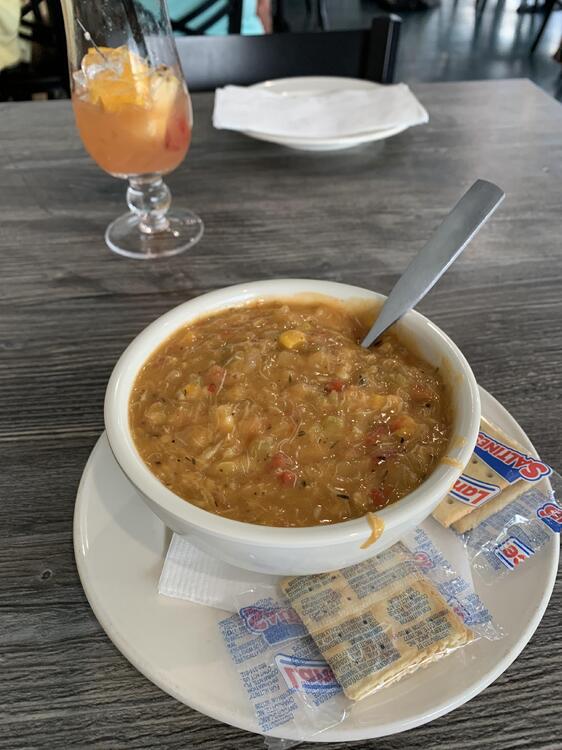
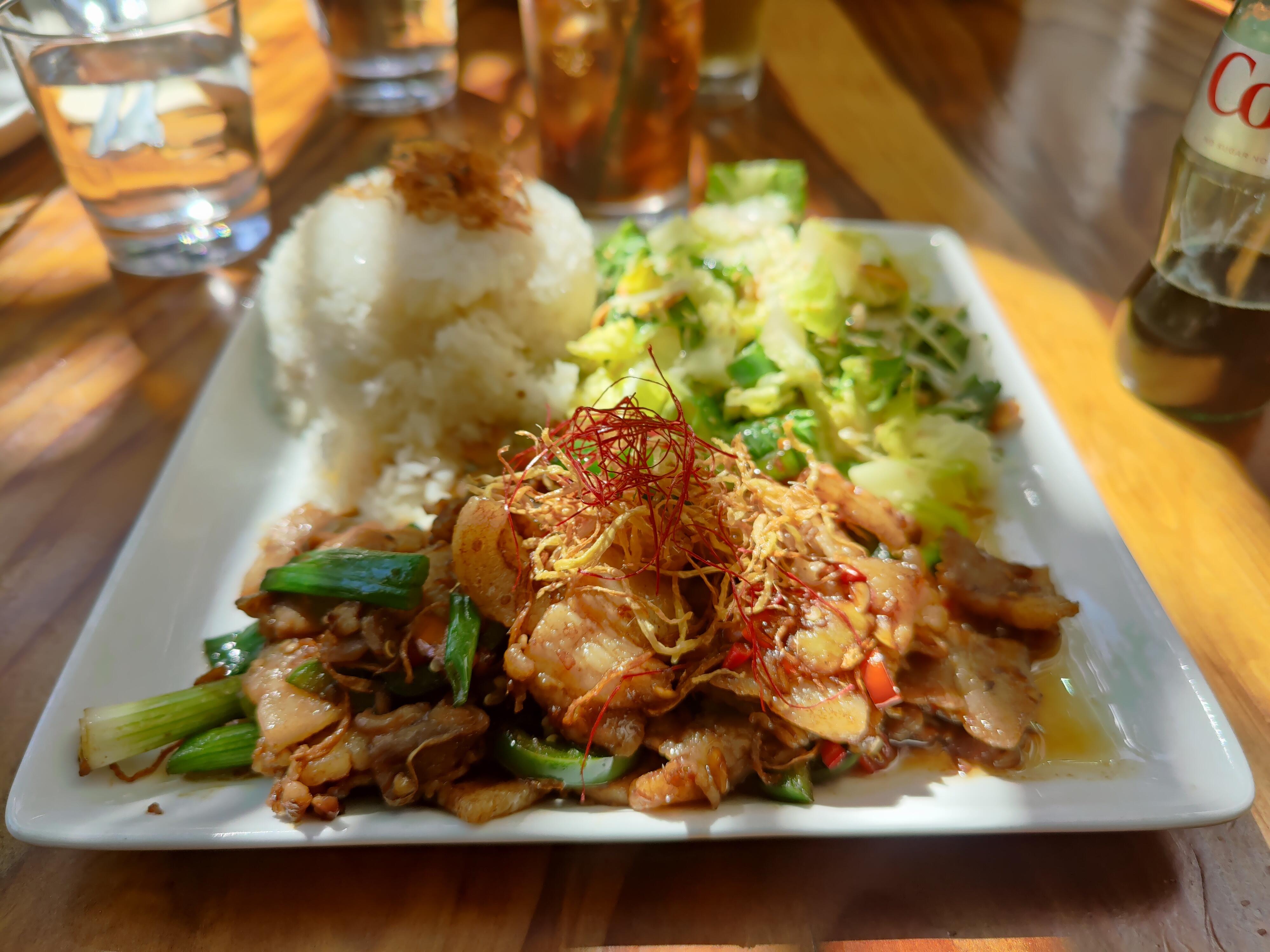
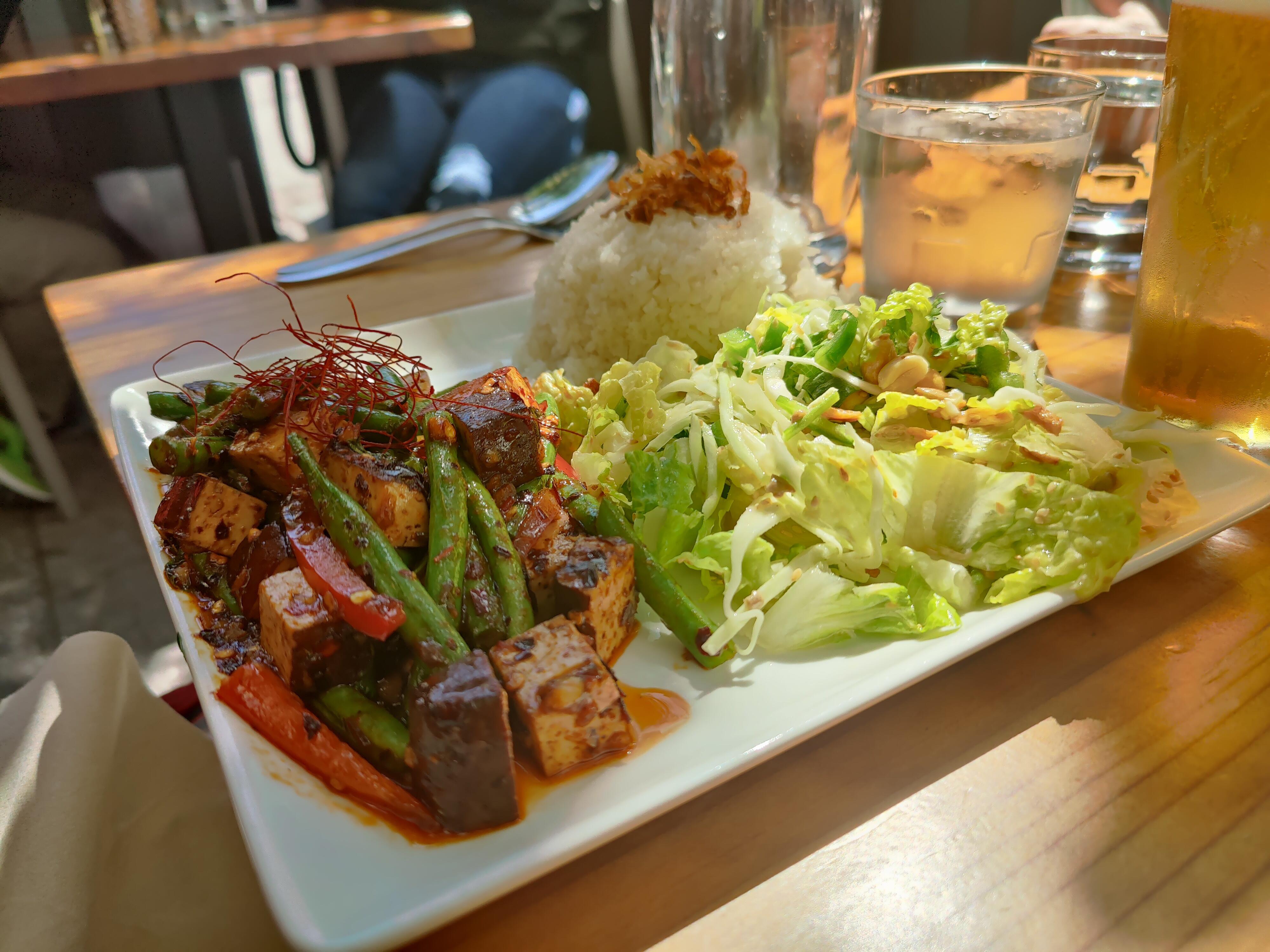
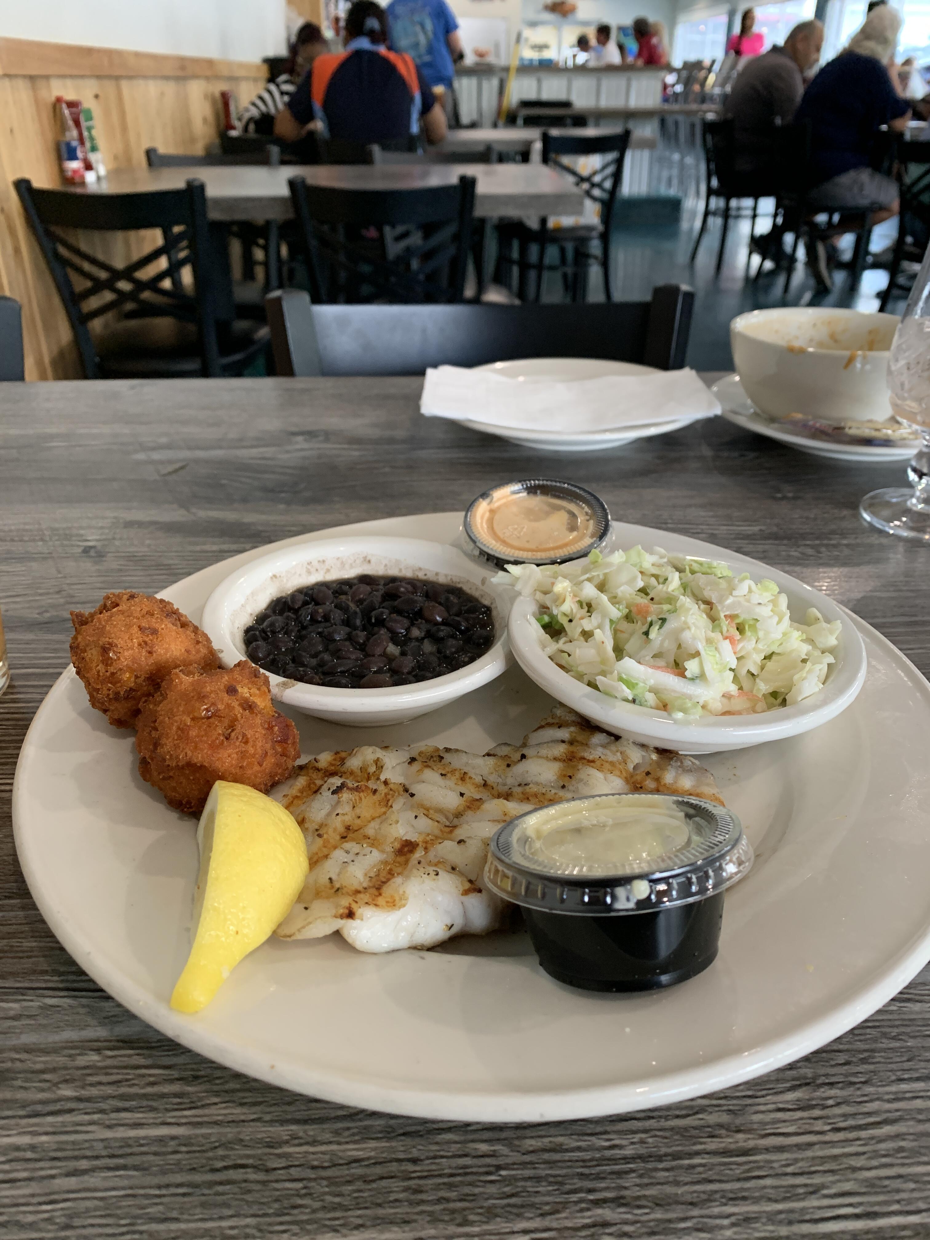
 1 pointOkay so I had a NAP today which, means I'm wide TF awake RN and therefore attempting to work on my show. This new version of Traktor has some strong "is that a feature or a bug" energy to it. Tonight I discovered 100s (of the 6600+) tracks I have in my record bag are not displaying key text. That's bad because I love to mix in key, but I am a dumb DJ and not a muscian so I need to know if that song is in Cm or not. Currently running a background process scanning the songs in questions. 1h10m remaining. I tried this once before and Traktor cheerfully ran the process but didn't write any tags. I futzed with config settings and I'm unsure if I actually fixed anything. I have a third party key detection software (the open source KeyFinder), which can write tags. Unfortunately, Traktor doesn't recognize those tags.1 point1 pointHad outer stitches removed from my neck today due a hole made recently extracting a growth. Not sure if it was ever really in doubt, but was tested and a simple epidermal inclusion cyst, thus benign. One of those I never felt in danger, but still felt strangely giddy when the expected test results came back.1 point1 pointDon't Look Back Boston 1978 https://album.link/i/158642228 Example: My friend and I were talking the other day about Boston (as you do), and we were saying that we don't seem to get to the other albums because Boston Boston exists. So, because I now have a streaming service, I immediately added Don't Look Back to my queue. I have to say any track could be added to their first album. For their sophomore release it is very good.1 pointIn spite of my considerable reservations as to his character, it turns out that the current on hiatus status of The Grand Tour has left me wanting more freakishly tall British jackassery in my life so when the Prive Video splash page (bless its heart) suggested this to me last night: I started watching. True to form, Jeremy is bad at everything. Also this show was filed right before Covid started, which certainly gives it a vintage feel. It's like watching pre-9/11 films in 2002.1 point1 pointKaren is out of town and Peter is hanging with his girlfriend so decided to check out a local seafood market/restaurant. They specialize in fresh, locally sourced seafood so everything below uses fresh, local seafood. Started with a dozen raw oysters since they are my favorite Followed by a bowl of their blue crab gumbo with a main entree of grilled grouper with hush puppies, Cuban black beans and coleslaw for desert I had key lime pie and a cup of coffee (no picture because the second Tiki drink was catching up to me - See Drinking Thread)
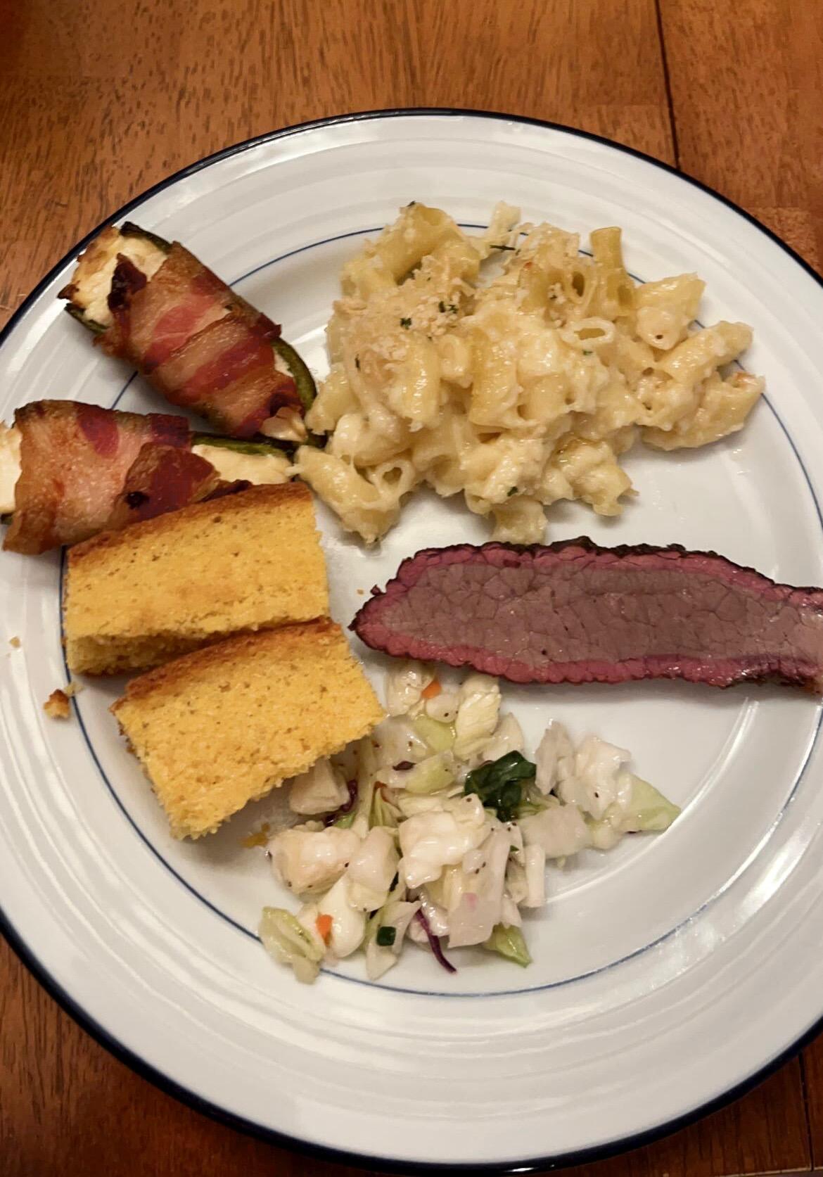
 1 point1 point100% home made dinner from last night: jalepeno poppers, mac and cheese, brisket, slaw, cornbread. The teenager took this to snap to her friends, so excuse the perspective, clipping, etc.
 1 point1 point1 pointIn a previous post I mentioned the less-than-ideal performance when Carbon is powered by a ±400V supply, and I suspected that the lower Vce on the PZTA42 is the culprit. Now it's been proven. The PZTA42 being a high voltage transistor, has a non-linear region at low Vce, as the slanted curves you can see on the upper left side. With 407V on the negative rail, the transistors on my board works at Vce=8.4V and Ic=20mA, right around the knee. The global negative feedback would have a hard time correcting that non-linearity. It also explains why some people prefer setting the Carbon at a lower current when powered with ±400V supply, as it also improves the linearity of the PZTA42, albeit to a lesser degree. I guess Kevin chose the high voltage PZTA42 to deal with the power-on transients. I have a quick and dirty fix. Just bias the SiC MOSFET a little higher to give the PZTA42 more headroom. The SiC MOSFETs are biased by two 175k and an 20k at the gate. Reducing either 175k or increasing the 20k would do. The goal is to move the PZTA42 operating point to the right, well into the constant-current region (parallel lines). I would use Vce=14 to 15V. Pushing it even higher would increase the power dissipation on the PZTA42, eat into the max output voltage swing and have diminishing return. What I did was to put a 260k resistor in parallel with one of the 175k resistors. YMMV because it has to do with the operating point of the PZTA42 in your circuit, the Vgs(th) of your SiC MOSFET, etc. After the quick fix, one of the channels now measures as good as with the ±450V supply. We can see that the max output voltage is slightly less compared to with ±450V supply. The difference is subtle with the log scale, though. Now I'm continue to work on the other channel and see if I can find something else.
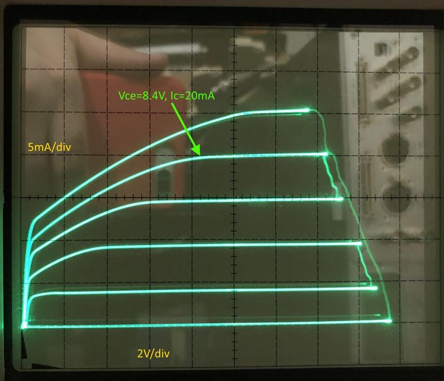
 1 pointBest lens is of course dependent on a lot including what you shoot, and some of these are only available to specific mounts and in specific mounts there are many other options, but favorite? That's easy. Ignoring the CV 50 APO-Lanthar (new and suffering due to second lens choice below) and CV 50 Nokton 50 f/1 (arrived Friday, but first results are encouraging**), the clear winner is the only lens mentioned twice (different mounts), but actually three times. I bought the Voigtlander Nokton 40 f/1.2 E for a Sony system with electric coupling. Although the A7III was my least favorite camera (skin tones under mixed lighting and controls from a Fuji analog control fan), that lens-camera combo was my favorite. When I moved to the M240 I went with the 50mm VM equivalent due to frame lines with the rangefinder. And then when I traded the M240 for a SL, I re-ish bought the Nokton 40mm f/1.2, VM version this time. And of course I haven't sold any of them 'cause I'm lazy. Those Noktons are the perfect balance between character and accuracy in my book. Just pick the 40 or 50 based on FL you prefer. And don't take my word for it. Take a glance at the longest running single lens review thread over at FM (if you run through all you'll even see a birthday boy's appearance in bubble popping fun). There's an argument the Noktons are when Voigtlander went from third behind Leica and Zeiss, to equals (and of course many of Zeiss lenses are also made by Cosina, Voigtlander's owner). And if you discount the Leica approved/branded Panasonics and Zeiss approved/branded Sonys, Voigtlander has released the most lenses and experiments in the last seven or so years. Less expensive is a plus too. Two lens prime option? A smarter person would spread out the focal lengths, but you're talking to me. I'd go for the Sigma Art 40mm f/1.4 (aka Beyond Art - one lens cine specs in a still body experiment - c'mon Sigma do it again!). The Noktons opposite. Big, heavy, 16 elements/12 groups, optically near perfect and will pull resolution out any sensor behind it. Also that auto-focus thing. And watch the pricing as it rotates mounts sales often. Currently Canon and Nikon users are in luck (Adorama a little cheaper than B&H). Check out the below video. I love talking about camera gear and hate doing comparison shots, but you can see examples on IG and less frequently updated Flickr. Same user name and lens always mentioned in IG description at least. Using rangefinder lenses without info sent to camera doesn't help on the Flickr side and again, did I mention I'm lazy? Ha! I'm a big believer in body-lenses combinations. Lenses are creeping up in price (approaching/matching older bodies used cost) and with sensor resolution jumps the old lens-body relationship isn't what it quite was ("date the body, marry the lenses"). If you don't mind using different systems, maybe find magic combos, instead of spreading out to all focal lengths. Or go with zooms which invalidates pretty much everything above. Please! I'm always curious about cases/bags/straps experiences. Recently for me it's been Clever Supply straps and Stone or LATZZ drawstring bags for each lens/body and then whatever non-descript backpack my company gave me or Timbuk2 messenger bag I picked up on sale, that doesn't scream camera(s) inside. ** This is one of the 13 shots I've taken so far. Momentary Roblox disruption yesterday. Again, this is mostly family stuff so anything I say has likely zero benefit to landscape, sports, street... pretty much everything, shooters. But typing this did allow putting off cleaning house for a bit!
 1 point1 pointFinally received the last of the components for the CFA boards today from DigiKey - Mouser who I usually use were out of a couple of items and whilst DigiKey had the values I needed, they didnt have them in RN60 so ended up going for the slightly more expensive CMF series resistors - was only for a few values so was not a big deal and am happy to have everything in now. Some quick soldering and the CFA3 boards are finished (except for the output transistors - they will go in when I have the cases and heat-sinking sorted out) - has been a long time between start and finish but I can feel the end of this build getting near. PS, managed to find a free way to host images - Google Firebase - so can now insert images without having to worry about chewing up quota1 point1 pointBlue hawaii build notes based on kgbhver6sbipolarinc. The amp board is fairly easy to build, but I do have a few observations 1. EITHER populate the LSK389 6 pin dual transistor OR the two single transistors each side NOT both EITHER populate the STN9360 smd transistors OR the KSA1156 just below them NOT both important and high voltage tracks run close to the screw holes for attaching the heatsink L brackets to the board on the top side of the pcb. I would be very wary about placing the L bracket on this side, if the solder mask is rubbed there will be a short to the L bracket which is probably electrically connected to the rest of the case and the case is probably connected to earth (certainly in countries with 3 pin mains leads) and that’s going to be bad.... 2. the tube sockets and trim pots go on the other side of the pcb to the rest of the components. If you want you can also put the leds on the top side so you can see what is going on. The 3 leds will give you an indirect indication of the status of the board. All 3 leds should be lit for normal operation. The led by itself gives an indication of the -400V line, the two leds closer together indirectly show the state of the +-15VDc lines. There is no led for the +400V line. 3. to set the constant current to 20mA you need to measure 1V DC across the 50ohm resistor near the trimpot (one for each valve). Since the trim pot is on the top side of the pcb it makes sense to put the 50ohm resistor on the top side two. I raised the resistor off the circuit board so I could easily clip insulated multimeter probes to the leads. 4. I found mounting the screw terminals to the underside was a pain in the ****. it may look neater BUT to screw the terminals you have to get to the underside of the board. BUT the pcb is mounted to an L bracket mounted to a large heatsink. So, you either have to flip the entire thing over.... hope you have long enough wires to allow this OR put the entire thing on a desk and stand on your head and screw upwards from below.... I am sorely tempted to desolder the screw terminals and mount them on the top of the pcb. 5. if you are going to have a single ended input to the amp e.g. RCA/phono then the -input should be connected to the ground for minimal hum. 6. when you are doing the inter board wiring for the first time make sure the inputs are shorted to ground. I got some instability issues because my input wiring was too close to either the stax output socket wiring or the main transformer and had nothing connected to it and was not shorted to ground. 7 when you build the amps boards set all the trim pots for halfway and verify with a multimeter in ohms mode. This will save you from having a trimpot at one extreme of its travel and result in LARGE DC offsets or high constant current pull.... 8. if you have a scope or two multimeters it’s much easier to set up the amp because changing the DC offset also makes the balance change and vice versa. With a 2-channel scope or 2 meters its far easier to chase the correct spot. Adjust the two trim pots near the 50ohm resistors have been adjusted for 1V across the resistor i.e. 20mA current, first. Next you can adjust the dc offset and balance between the valves, the audio inputs should be shorted to ground and no headphones attached for all setup. If you are using a scope make sure it’s set to DC coupling... AC coupling will ignore any DC offset and its DC offset we are trying to null out. Also, if you have a scope do no connect the ground terminals of the probes to anything only the centre pin of the probes is needed. (almost all scopes internally are grounded via the main input) almost all multimeters are NOT and require the ground lead connecting to the amp board or psu ground. 9. Im my experience if you are building a single box amp, even if the transformer has a magnetic shield foil, putting the audio input wires anywhere near the transformer will result in hummmmmmm..... the magnetic field is STRONG with this one... 10 The hottest transistors on the blue hawaii are the FQPF8N80Cs, measuring the mounting screw of the transistor - (which seems to be the hottest part I can find) I get a stable 65C after multiple hours of use, this is using arctic ceramique thermal paste, aluminium L bracket 200mm by 80mm heatsink with 40mm fins and aluminium oxide insulation pads.... 20mA constant current and +-400VDC B-+ 11. double check which trimpot you are adjusting. I have adjusted the constant current trimpots by accident when trying to do DC offset and balance multiple times.... 12 some labelling of the trimpots to say what does what on the silkscreen would be nice... 13 labelling the screw terminals on the top side of the board would be nice for checking wiring after the boards are in place. I hope this is useful James1 point1 pointBlue hawaii build notes for the kgsshvpssicfetdual2new PSU The kgsshvpssicfetdual2new is based on version 1.6 of the kgsshv psu single boards and does NOT have the cpc1117N or resistor required for simple B+,B- delayed start. (it’s still possible to implement delayed start but it requires a relay(s) which the cpc1117N avoids). In all other ways its similar to the v1.7 single boards. The single boards put the b+ on one board and the b- on another and split the -+15V and bias between them. The kgsshv ps dual has all the dc voltages required to power the blue hawaii and apart from the notes above is topologically and componentry identical to the single psu boards. The notes bellow applies to BOTH the single and the dual psu boards. Construction is straightforward other than 1. the silkscreen shows 15-0-15VAC input for the + and 15VDC outputs, Since the -+15V output is a simple DC supply with a bridge rectifier and voltage regulators 15-0-15VAC is NOT sufficient to provide -+15V output... I have verified this using a variac. There is about 0.6V drop across each diode in the bridge *plus* the voltage regs need between 1V and 1.5V more input DC than their output in order to regulate properly. so 18-0-18AC is actually required to get a properly regulated -+15VDC output... Any more VAC input will be converted into heat by the voltage regs. However, with 18VAC-0-18VAC centre tapped input the voltage regs run very cool with the small heatsink they are bolted to. 2. the blue hawaii amp boards -400VDC lines draw more current than the +400V lines. If you connect a single channel up to the psu board for testing there will be no problems. Connecting two channels results in the -400V line on the psu going into current limit and the voltage dropping to (im my case) about -175VDC. The fix is fortunately easy. The 5.1ohm 3W or 5W resistors are the current sense resistors for the over current protection. On the -400V psu side either replace the 5.1ohm resistor with about 2.6ohm or similar wattage and type or parallel another identical 5.1ohm around the existing one. The +400V does not need modification. the lower the resistors value the more current supplied before the current limit cicruit activates. I don’t have anyway to variable load a line that has such a high voltage but I would guesstimate that the 5.1ohm resistor current limits at about 100mA since two amp boards +400V together draw around 81mA and there is no problem with 5.1ohm and 2 -400V boards draw between them around 129mA and that causes current limiting with 5.1ohm sense resistors. 3 make sure none of the metals tabs on the transistors are shorted to the heatsink/L bracket that mounts to the heatsink. Use electrically insulated spacers between the back of the transistors with metal tabs and the L bracket/heatsink AND use a nonconductive gromet to insulate the bolt from the transistor. The psu transistors do not get that hot with a reasonable size heatsink attached. 4. if you are building in a u2 high case the largest main psu caps you can put in are Kemet 500V 470uF long life at 65mm tall. Beware they also do an 80mm tall 470uF cap - this will NOT fit in 2u. Similarly 680uF caps at 500V are 80mm high and will not fit. 5. if you want to check the bias is 580V use the bias test point. Dont measure at the bias screw terminal. Why, typical multimeters have a 10M ohm input impedance and assume whatever they are measuring across is much less than 10Mohm... this is NOT the case for the bias line which has a 4.7Mohm resistor. result the multimeter will NOT give the correct voltage reading between the ground screw and the bias screw. Measure from the bias pad nearby to the ground screw. Also, don’t measure the bias with headphones attached. 6. there is only one screw terminal for +400V, -400V, +15V and -15V so you will need to connect two wires to each screw terminal. This limits the gauge of the wire. Also make sure you are screwed the terminal down well, its easy to have one wire firmly affixed and the other one lose.... 7. to adjust the B+ and B- lines the two 390K resistors (R8 and R9) in series with the 20K resistor (R7) just after the 1N007 diode that have the 0.047uF cap across them need to be changed. Approximately (for my psu) I got the following 442K for 450VDC (note requires a transformer with 360VAC output to have enough voltage input to get proper regulation) 390K for 404VDC (transformer 330VAC or more output) 365K for 375VDC (transformer 310VAC or more output) the approximate equation for me was the total of the 2 resistors in ohms/(20,000-700)*10 (the 20,000 is the resistor in series with the resistors you are changing, the 10 is the output of the voltage reference LT1021-10), the 700 is the fudge factor to make the numbers accurate for me... (variation in voltage reference, variation in the 20K resistor etc etc...) 8. To test for proper regulation connect a volt meter to the nominally +-400V output and a ground screw terminal and either power the transformer from a variac OR if your variac can go high enough you could go from the variac output into the 300VAC input of the psu. There is no need to have amp boards connected at all and its safer if you dont. Slowly increase the AC and you should see the DC output rise. At some point increasing the variac by some volts will result in very small output increases (in the order of few milli volts) now the psu is regulating. Measure the 330VAC input of the psu and that’s the minimum transformer output voltage you need for regulation. Both the + and - 400V sides of the psu should have similarly behaviour and similar minimum VAC input requirements since they are almost identical in topology and are identical in components. 9. I would recommend initially testing the psu board without amp boards connected in case voltages are way off. However, with no load on the psu the b+ and b- lines, they will take some minutes to fall to 0v and with no headphones the bias line will stay high for a long time. Fortunately the bias line can be discharged just by connecting a multimeter to it and ground and set to DC volts. Even a meter with 10Mohm input impedance will drain the bias line in a few minutes. the -+15V lines will be drained by the voltage regulators. 10 I would recommend a variac for initial testing it allows you to bring voltages up slowly and make sure that voltages are going up in symmetry (-+400V, -+15V) and becoming stable. 11. If the outputs look good with no amp boards attached, connect one board and repeat the tests. Better to put in channel in danger than both... especially if the amp boards have not been tested. 12. if test with the other amp board only. You don’t want to blame the psu if one amp board only is miss behaving... 13. test with both amp boards. Remember if the -400V line goes down in voltage significantly only with 2 amp boards attached and is fine with one you probably have a current limit problem and did not implement item 2 here! 14 don’t plug in headphones unless 1. you have a spare pair you don’t mind frying. 2. you have tested voltages, dc offsets are nulled and you are happy. ideally look at the outputs on a scope and put some sine waves in.... 15 Before you plug in anything visually inspect for solder bridges... I had a partial bridge it only started conducting when the input AC to the psu went above about 26VAC... thank you variac... 16 use probes with insulation, there is lots of high voltages don’t short out things with you probes.... 17 Before you power up anything double check the wiring the - and + on the silkscreen are quite small and you dont want +400V going to a place expecting -400V.... 18 temperatures are low, with the psu attached at a 200mm by 80mm heatsink with 40mm fins, (both amp boards running constant current 20mA and -+400V B-+), the centre of the case of the +400V side transistors are about 40C, the -400V transistors are around 3C higher at around 43C. The cases on the C2M1000170D transistors take some time to become as hot as the mounting screws. The 10M90S cases reach the mounting screw temperatures far faster. 19 I know the board has been made as small as possible and around the screw terminals its rather crowded. But it would be nice if there was sepertate screw terminals for the -+400V and -+15V for each channel, this would allow for the use of thicker wires and reduce the possibility of a wire comming out. (I have already had the situation where I though both wires where screwed in tightly to a single terminal and then one came out) Hope this is useful James1 point1 pointFor anyone building a blue hawaii, here are the current draws for my build after 5 minutes of power on, rounded up to the nearest mA. These figures provide no margin for variation, to headroom for inrush on power up and should not be considered minimum specs for the transformer... PSU board set to 400V output (actual around 404V) constant current on the amp boards set to 20mA per valve inputs shorted to ground no headphones attached groove tubes el34 kemet long life 470uF caps @ 550V for B+ and B- Boards used: amp Blue Hawaii kgbhver6sbipolarinc PSU kgsshvpssicfetdual2new (single board version 1.6 with no delayed start cpc1117n that appeared in ver 1.7)total for both channels: -15VDC line draws 10mA +15VDC line draws 11mA +400VDC line draws 81mA -400VDC line draws 128mA EACH 6.3VAC line draws 3.1A Primary side current draw 0.67A @230VAC All Measurements made on a Brymen bm869s multimeter. NOTE With @230V primary the inrush current is significant and will blow a 3A fast blow fuse on power up, and blow a 4A fast blow after half a dozen power ups (tested with no B+- delay circuit). With a delay circuit 3.15A Timed fuse looks good. transformer I used (which is overkill, but as a result the transformer generates very little heat. ) 330VAC 300mA 330Vac 300mA 36V AC centre tapped 200mA 18v-0-18v 6.3VAC 4.5A 6.3VAC 4.5A Now I have measurements I would say that the transformer could be scaled down to somthing like 330V 250mA 330V 150mA +18V centre tap -18V 50mA 2x 6.3V 4.5A I hope this post will help someone. regards James1 point1 pointalthough you certainly can (singlepower es1,es2...) when you apply high voltage with the tube cold, the cathode can strip. with the diy-T2 applying high voltage with the tubes cold does all sorts of bad to the input tube, putting +500 on the cathode with the filament grounded. soft start on an el34 seems like a waste of time, haven't seen anyone do that. On expensive DHT's, might be a good idea, might be a waste of time.1 point1 pointProbably should ask this in the GRLV thread, but I'm curious why the BOMs I see show Elna Silmic caps for the 220uf caps on the PSU? Usually audio grade caps are spec'd for coupling caps (Pass seems to like them), but for a PSU? Some reason that I am missing? I used Pana FM/FR for the ones I built. Sent from my iPhone using Tapatalk1 point0 pointsI love it when you find metal in your expensive wood by running it over the jointer. That is all.0 points


Important Information
By using this site, you agree to our Terms of Use.
Account
Navigation
Search
Configure browser push notifications
Chrome (Android)
- Tap the lock icon next to the address bar.
- Tap Permissions → Notifications.
- Adjust your preference.
Chrome (Desktop)
- Click the padlock icon in the address bar.
- Select Site settings.
- Find Notifications and adjust your preference.
Safari (iOS 16.4+)
- Ensure the site is installed via Add to Home Screen.
- Open Settings App → Notifications.
- Find your app name and adjust your preference.
Safari (macOS)
- Go to Safari → Preferences.
- Click the Websites tab.
- Select Notifications in the sidebar.
- Find this website and adjust your preference.
Edge (Android)
- Tap the lock icon next to the address bar.
- Tap Permissions.
- Find Notifications and adjust your preference.
Edge (Desktop)
- Click the padlock icon in the address bar.
- Click Permissions for this site.
- Find Notifications and adjust your preference.
Firefox (Android)
- Go to Settings → Site permissions.
- Tap Notifications.
- Find this site in the list and adjust your preference.
Firefox (Desktop)
- Open Firefox Settings.
- Search for Notifications.
- Find this site in the list and adjust your preference.