Leaderboard



Popular Content
Showing content with the highest reputation on 06/05/23 in all areas
-
6 points
-
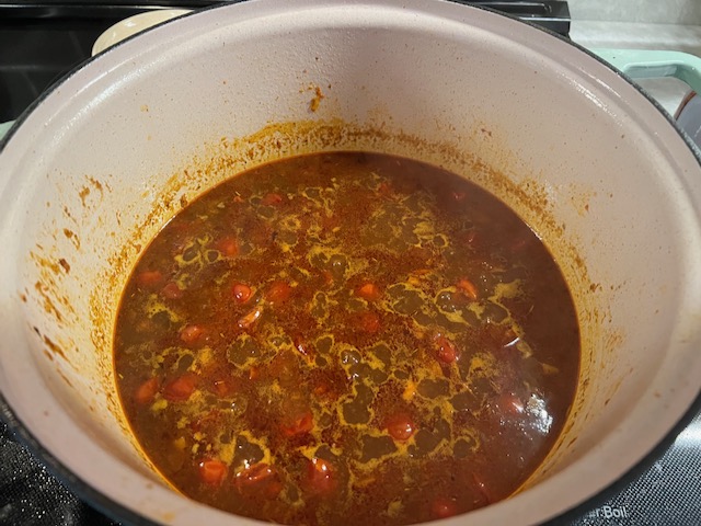
5 pointsMade red curry today based on a NYT times soup recipe that I tweaked to be thicker and serve over rice. Came out quite good.
 5 points
 -
4 points
-
The Cars (2016 Remaster) The Cars 1978 https://album.link/i/1088527349 Example: It has all the hits and all the goodness in-between. I grew up listening to Candy-O so much more than their freshman effort. Just a well crafted album with great tracks and riffs one after the other. It will not be lost in my history.4 points
-
4 points
-
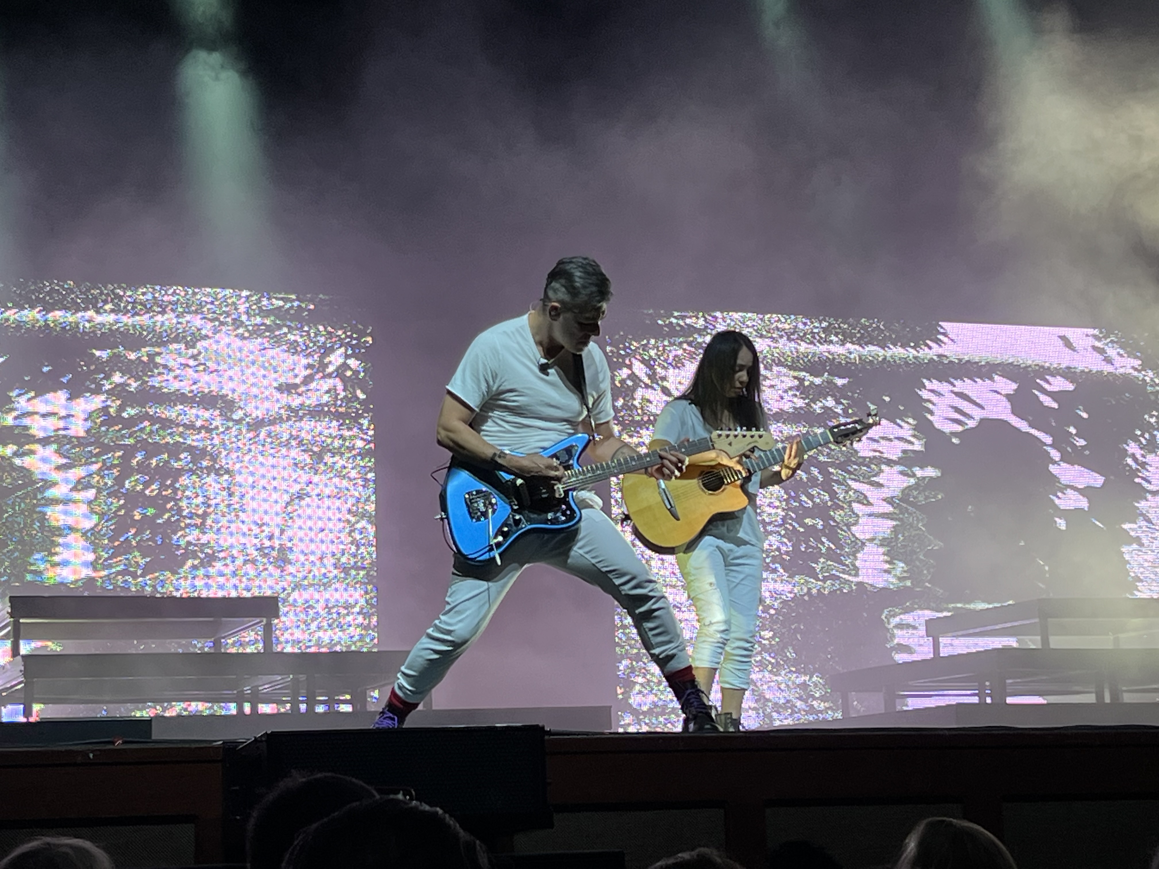
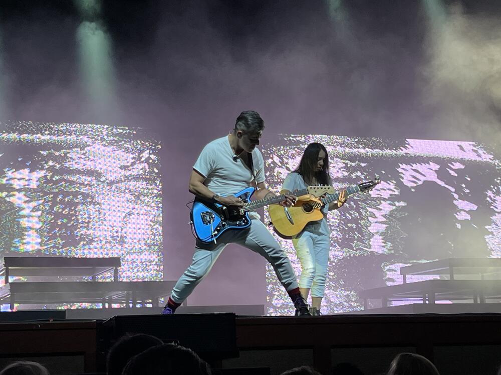
3 pointsRodrigo and Gabriella last night @ the Fox Theater in Oakland. Love that these two are still doing their thing and fun to get to see them at my favorite Bay Area venue. That woman can really play some rhythm guitar! Rod ain’t bad on lead either.


 3 points
 -
2 points
-
2 points
-
2 points
-
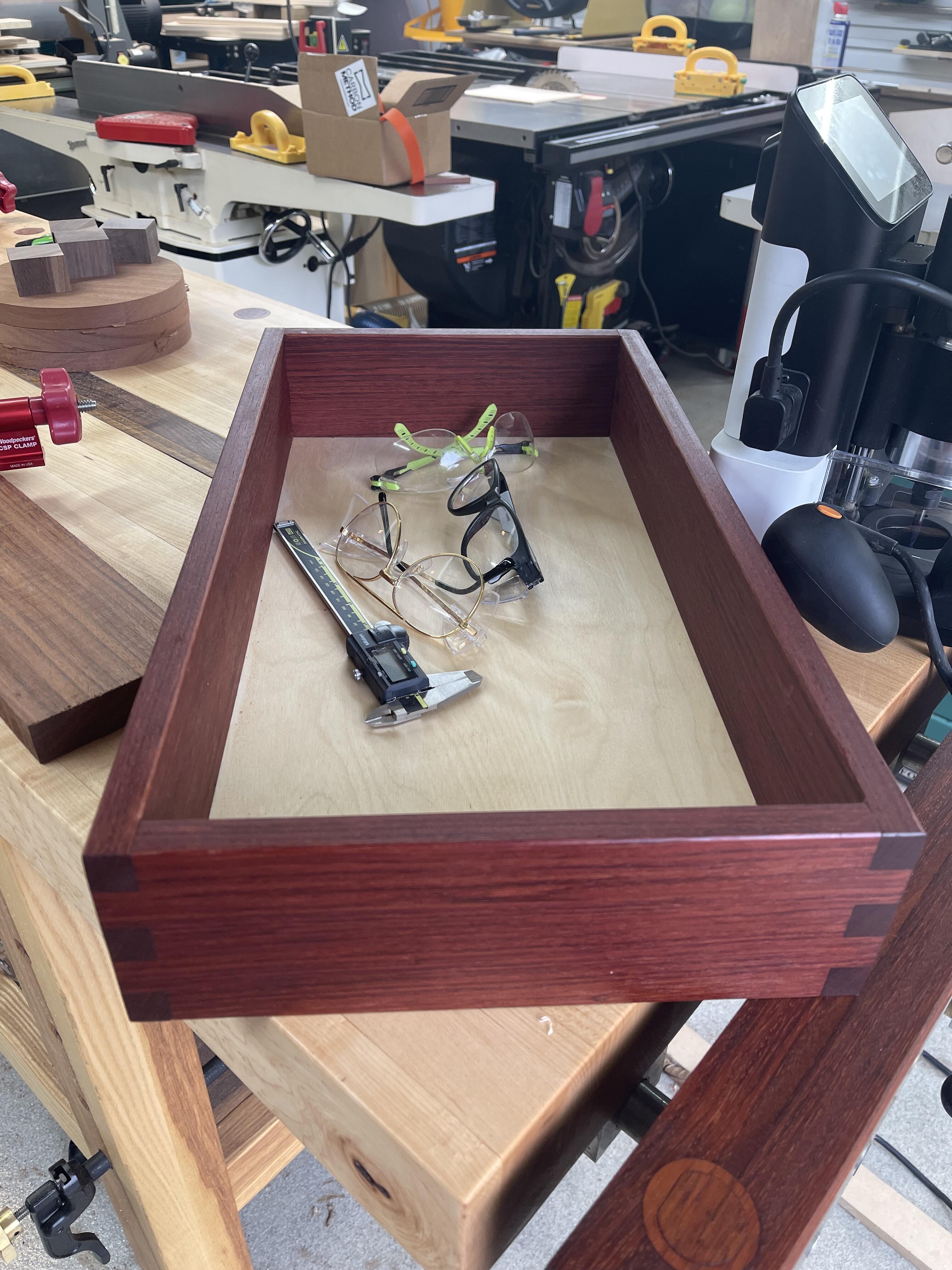
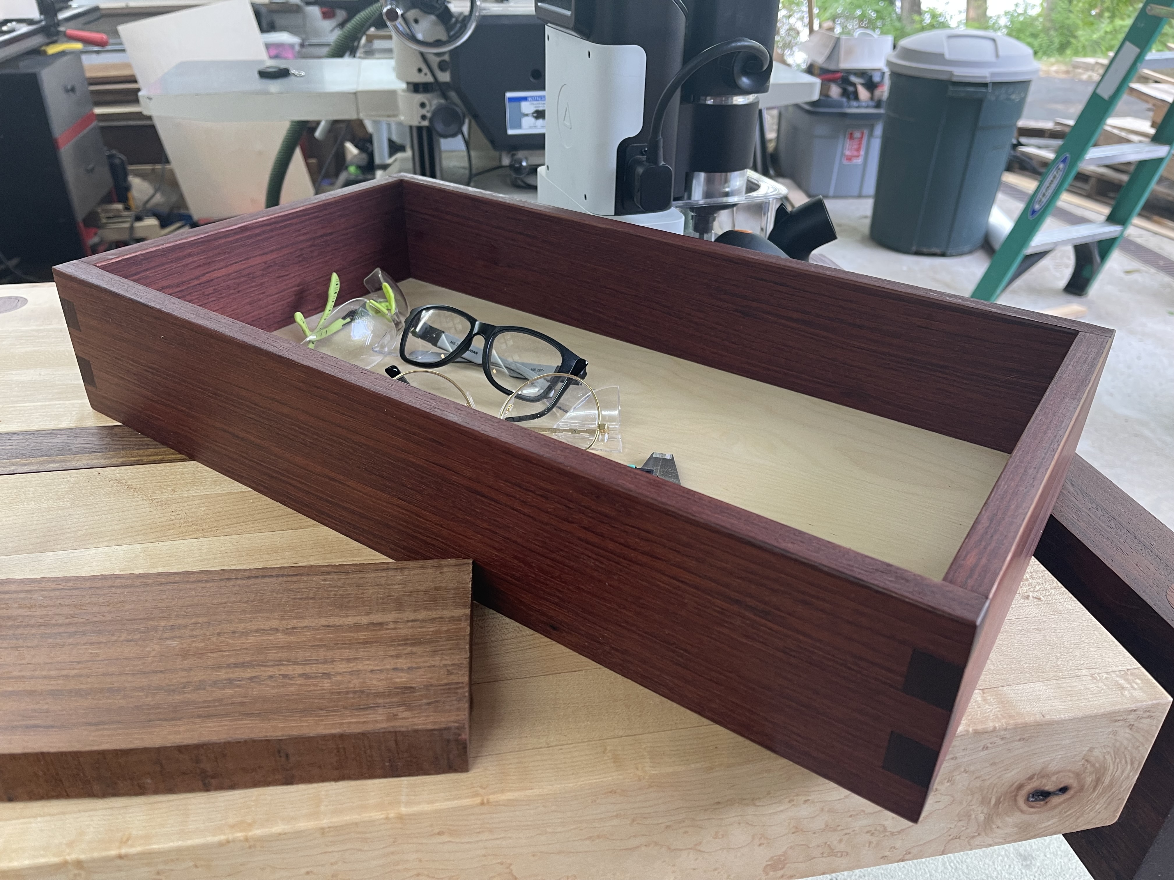
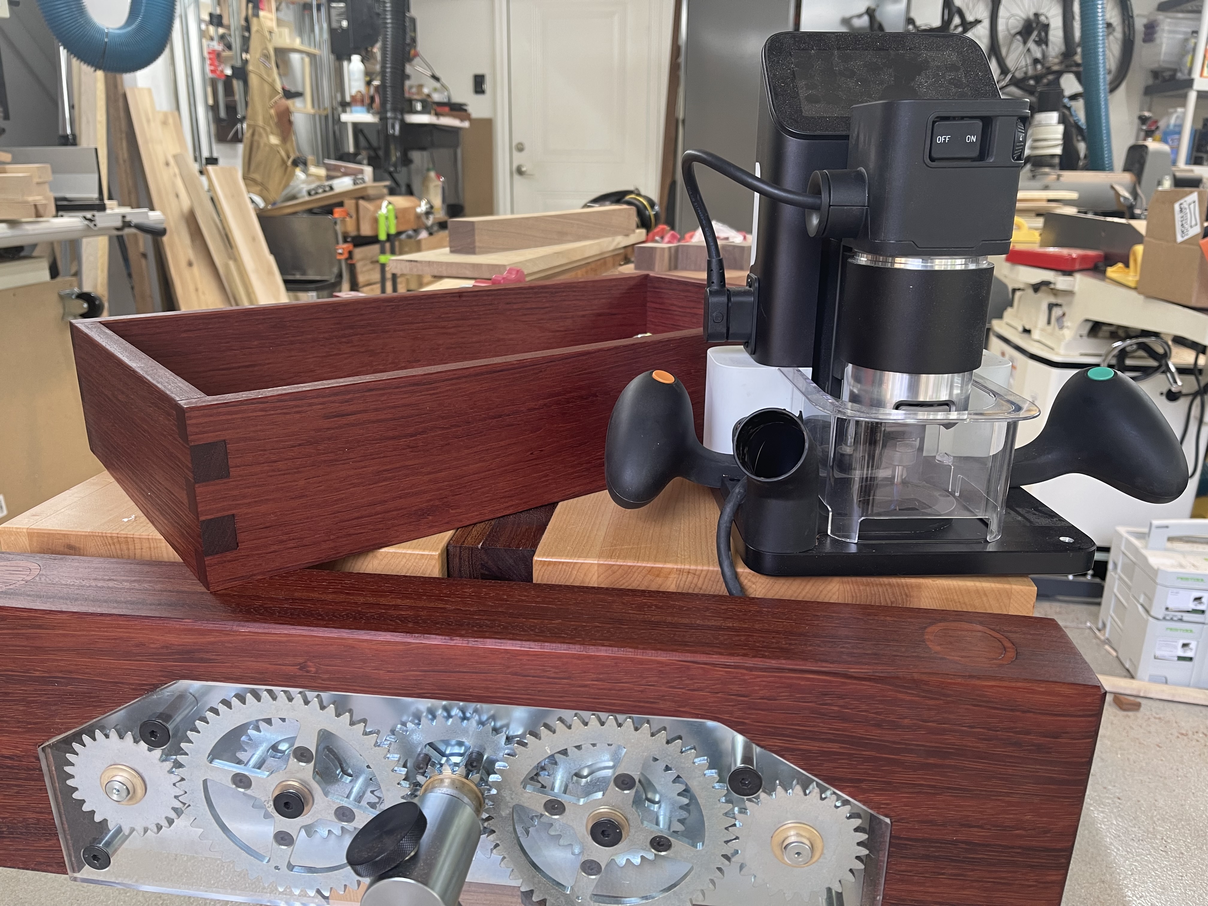
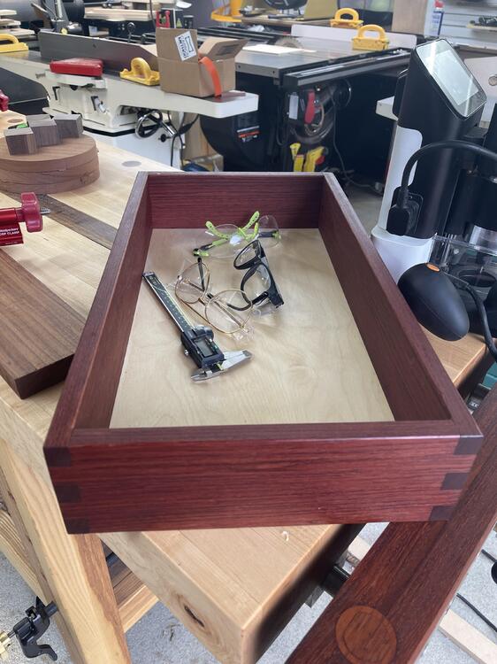
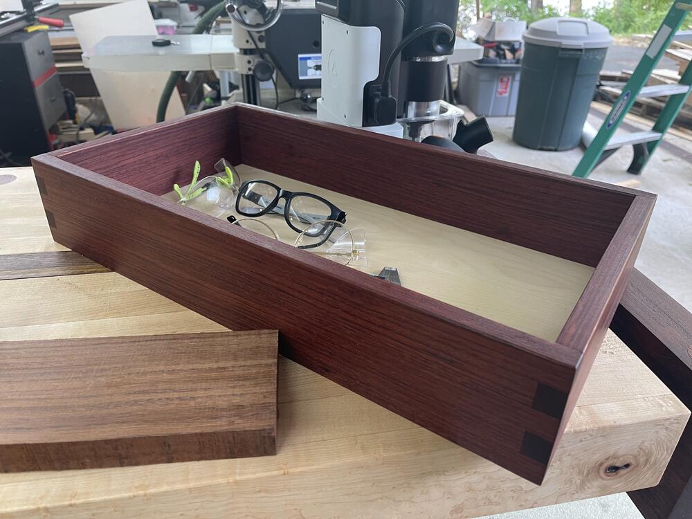
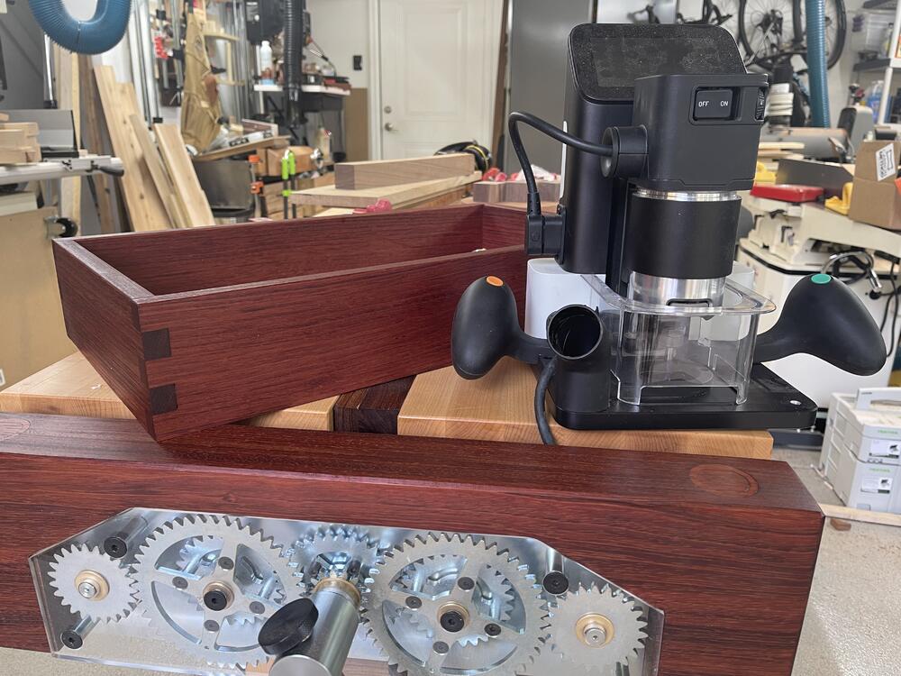
2 pointsBuilt a tray to store all the shit constantly in my way on the new workbench.
 2 points
 -
2 points
-
2 points
-
1 point
-
1 point
-
A few recent watches: On AppleTV, Silo - why are people living underground in this dystopian future? On Hulu, The Class of 09, an interesting portrayal of how a surveillance-state develops: Also started on AppleTV, High Desert, for some comedy: Decent, if not great watches so far - soft recommendations, all. They could all use some tightening up, storywise. But then they'd be movies instead of a series, I guess #shrug.


 1 point
 -
1 point
-
gerbers: https://drive.google.com/drive/folders/1r3g2TAtBUaBdiMorTWX7yYgeJ7maQbYW schematics and other things: https://drive.google.com/drive/folders/0B7egryukiT7_TFlEQlBRejdVdDQ?resourcekey=0-nGWwBYQ_Uivj-ciBLYMeaA1 point
-
1 point@demonkuro Sorry to be blunt, but people here who help you have their way of troubleshooting issues. To get the most out of their expertise, please do the measurement they asked so they can better help you. Extra measurement may help, as long as they are well documented. For instance, are the voltages marked on you schematic from the R channel? Also, doing shotgun-style component replacement without narrowing down to a suspect is rarely effective. Apparently the problem on the right channel is a balance issue. The final stage offset servo is most likely working fine. That's why replacing Q30 thru Q33 didn't help. Measuring Hfe of the transistors in circuit would not give you accurate results, especially when the base and collector are shorted together in the circuit. Assuming the voltages marked on you schematic are from the R channel. They look reasonable. There is one volt difference between the cathode of the EL34s (457V-456V). The triode-connected EL34 has a mu of about 10. For a matched pair under the same current, 1V of difference should create about 10V of difference between their anodes. But now there are 50V. That could be caused by different currents from the CCS. Measure the voltage drop on R18 thru R20, R17 and R14, and you'll get an idea how much current is flowing through the CCS. Do the same on the other arm and compare. To check the operation of the balance servo opamp that seems stuck, I suggested that you 'Follow the trace from O+/O- all the way to IN+/IN- of the opamp and see where the problem is.' I didn't see any feedback from you. Now that O+/O- differ by 50V, points C and D should be 5V apart, IN+/IN- of the opamp should be clamped by the diodes to approx 0.6V in the correct polarity, and both opamps should output close to rail after a few seconds. If you don't get the correct IN+/IN- voltage, you may have a short or a diode installed in a wrong orientation. If you do get the correct IN+/IN- voltage but the opamp still outputs zero, you may have a bad chip or a leaky cap (0.47u). BTW, film caps (polypropylene) are recommended over ceramics in those locations for lower leakage. It's a pain in the butt to remove the C3381s, but quite easy to check if they work correctly in circuit. They are used as current mirrors. Current that flows thru R86 should be roughly the same as the current that flows thru R84. Measure the voltage drops and you'll have an idea. Remember that I asked you to measure the top and bottom voltages of both active batteries of both channels? That would tell us if the imbalance is from the front-end or back-end. In other word whether the imbalance is before or after the active batteries. Before the balance issue is resolved, it's probably not necessary to repeat the hour-long tests. A better way is to take as many points of measurement as you need in one shot, shut off the power, analyze the data and go from there.1 point
-
1 point
-
1 point
-
1 point
-
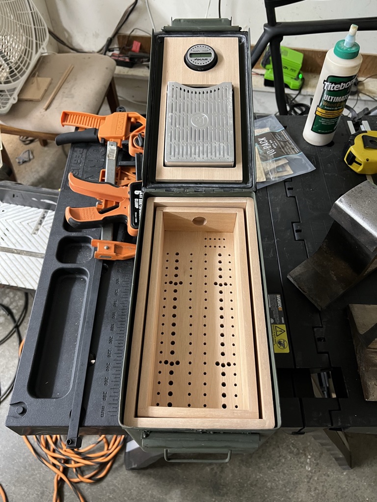
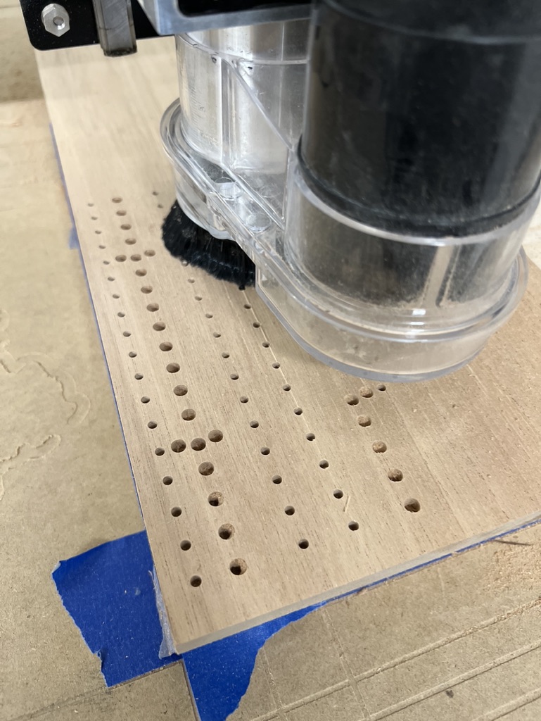
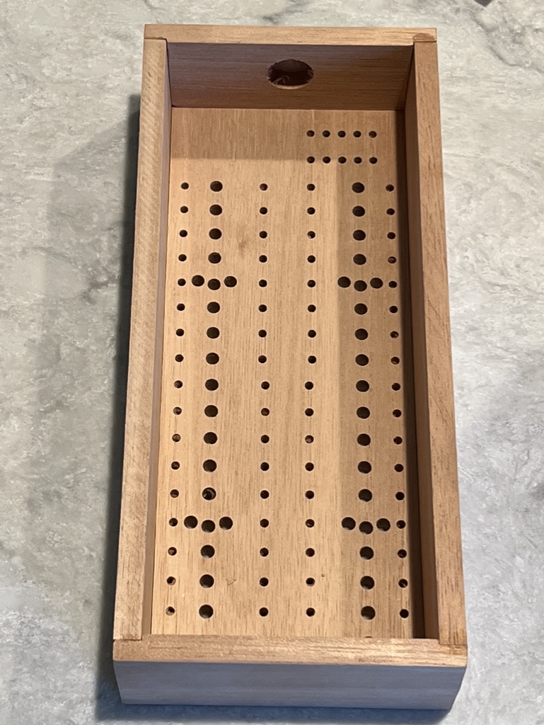
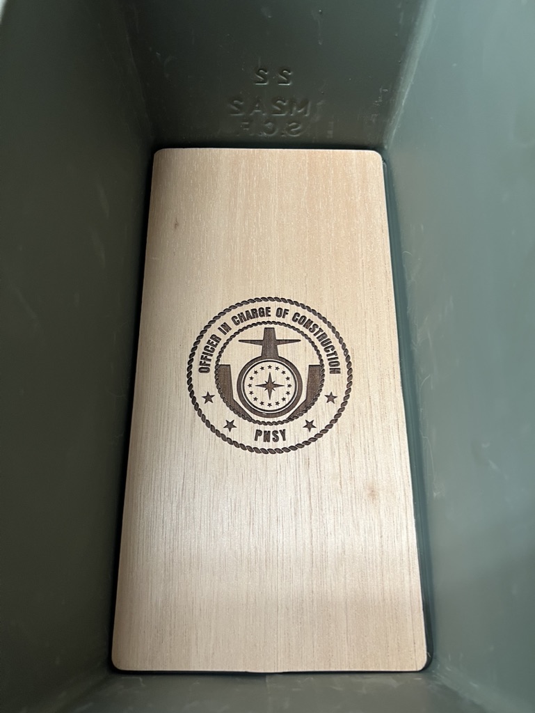
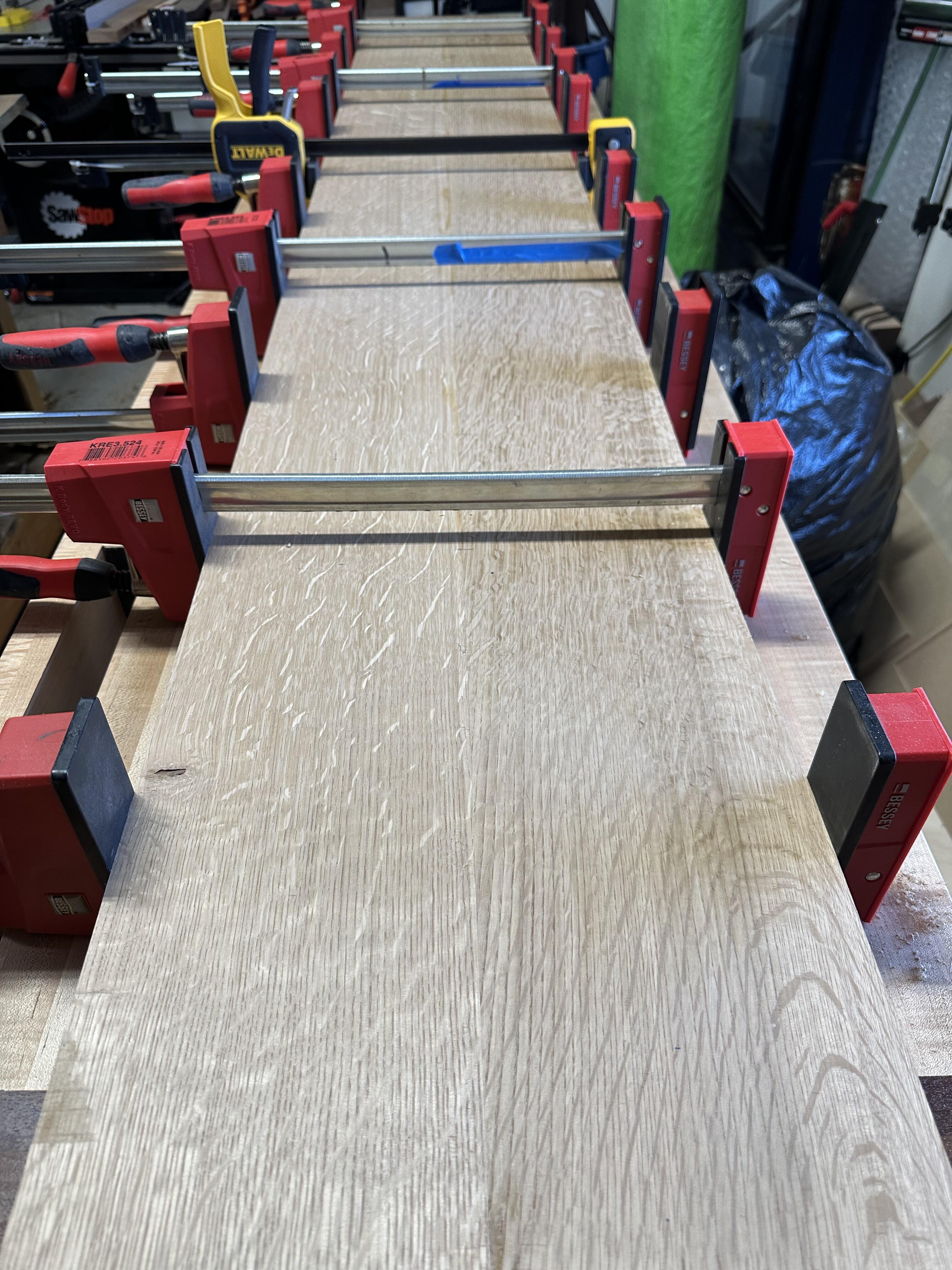
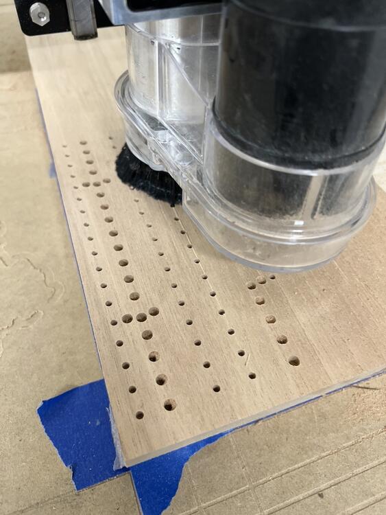
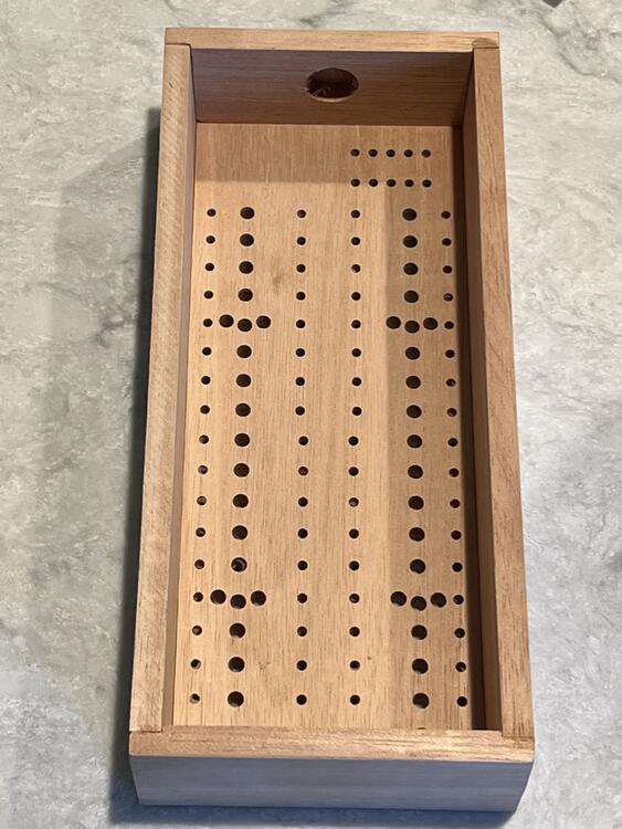
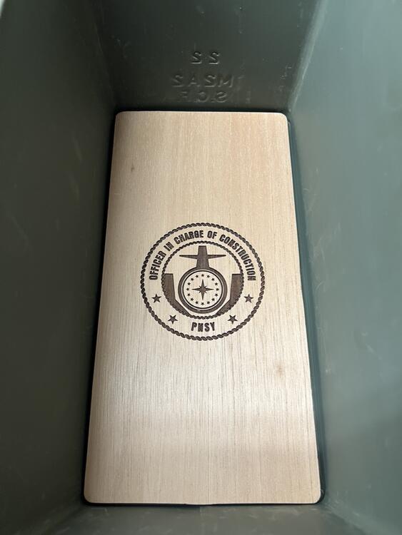
1 pointWork on the humidor project continues and should be complete this weekend, well it sort of has to be since the presentation of the gift needs to happen Tuesday. WIth that in mind I did some more fab work on limited time at night this week making the piece for the bottom of the removable tray and doing a bunch of sanding. Precision was applied in some areas and is lacking in others, such is the nature of the things that I make. This is the custom bottom panel for the tray. The air-flow holes are a pattern that I developed to mimic the drilled shaft foundations that we are currently installing to support the two new dry docks. The large holes are the 9 foot diameter shafts that will start installation this fall/winter and the smaller holes are the 6'-6" shafts we're in the process of installing now. This is the bottom panel of the box complete with laser-engraved command logo.
 1 point
 -
Cry Softly Lonely One (Remastered) Roy Orbison 1967 https://album.link/i/1443310520 Example: You may not know them all - but they are worthy.1 point
-
Schubert: Symphonies Nos. 3 In D, D.200 & 8 In B Minor, D.759 - "Unfinished" Wiener Philharmoniker, Carlos Kleiber 1997 https://album.link/i/1585387022 Example: All around a super solid performance and recording by DG. Engaging, pretty and good pace. Very much enjoyed my time with this one.1 point
-
1 point
-
For some reason, your post made me wonder if Randy Newman ever sang Cars and I found this0 points