

Leaderboard


Popular Content
Showing content with the highest reputation on 08/17/23 in all areas
-
3 pointsMany people knew him as a country singer. Some knew that for a short time he was a Beach Boy. Not many know that before his singing career took off, he was a member of The Wrecking Crew, and an extremely well respected studio guitar player. In fact, one day when The Wrecking Crew showed up for a scheduled recording session, Glen happened to be standing in front of a microphone. As members of the crew teased him for his humor, they were quite surprised to find out that they were actually there to lay down music for Glen Campbell's first album. Anyway, here's Glen picking the William Tell Overture.3 points2 pointsMeanwhile @ https://www.sonomastuesdaynightmarket.com/ Veggie Flatbread Straight from the oven. And a dim sum platter with extra pork buns!


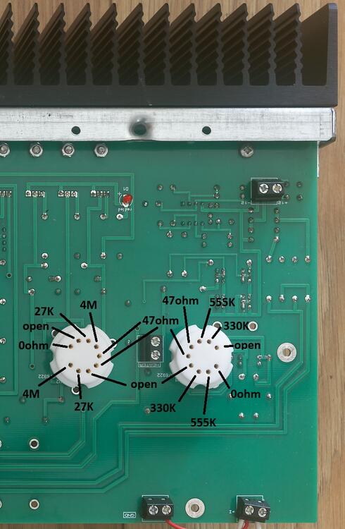
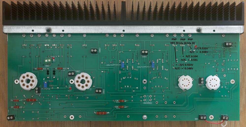
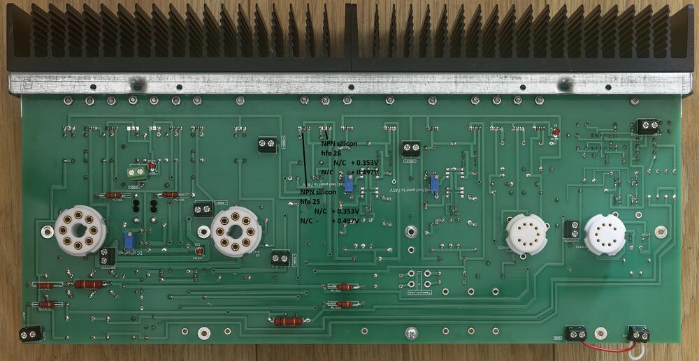
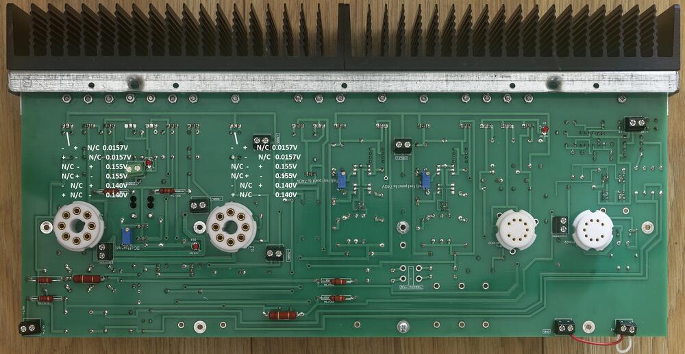
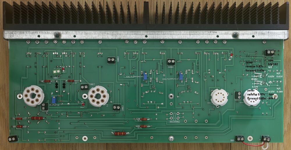
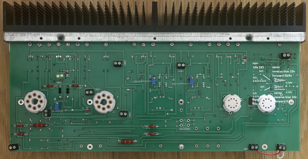
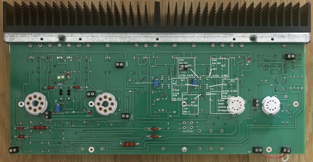
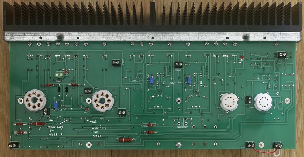
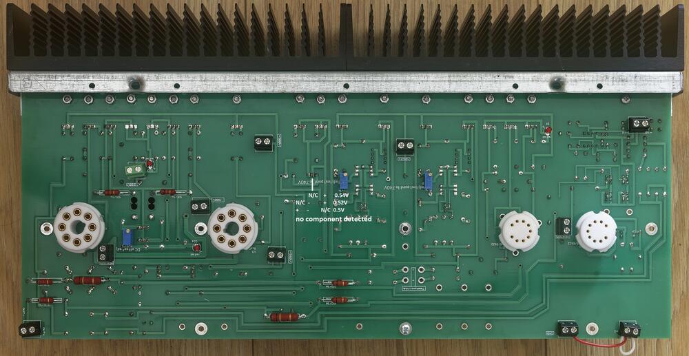
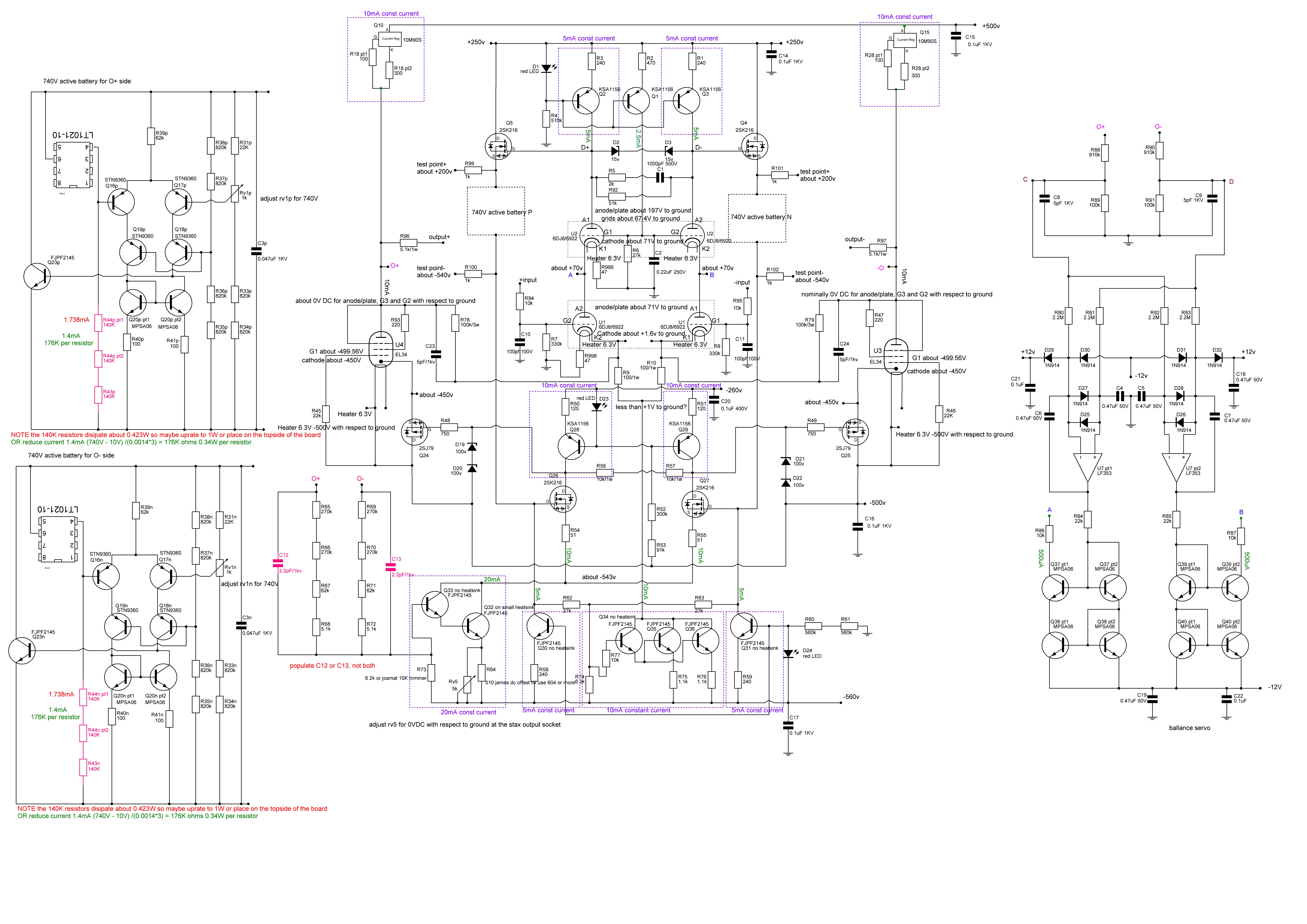
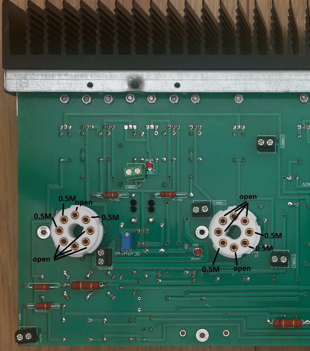
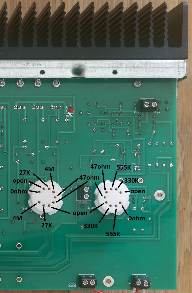
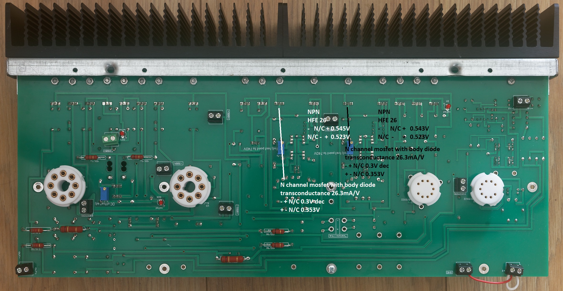
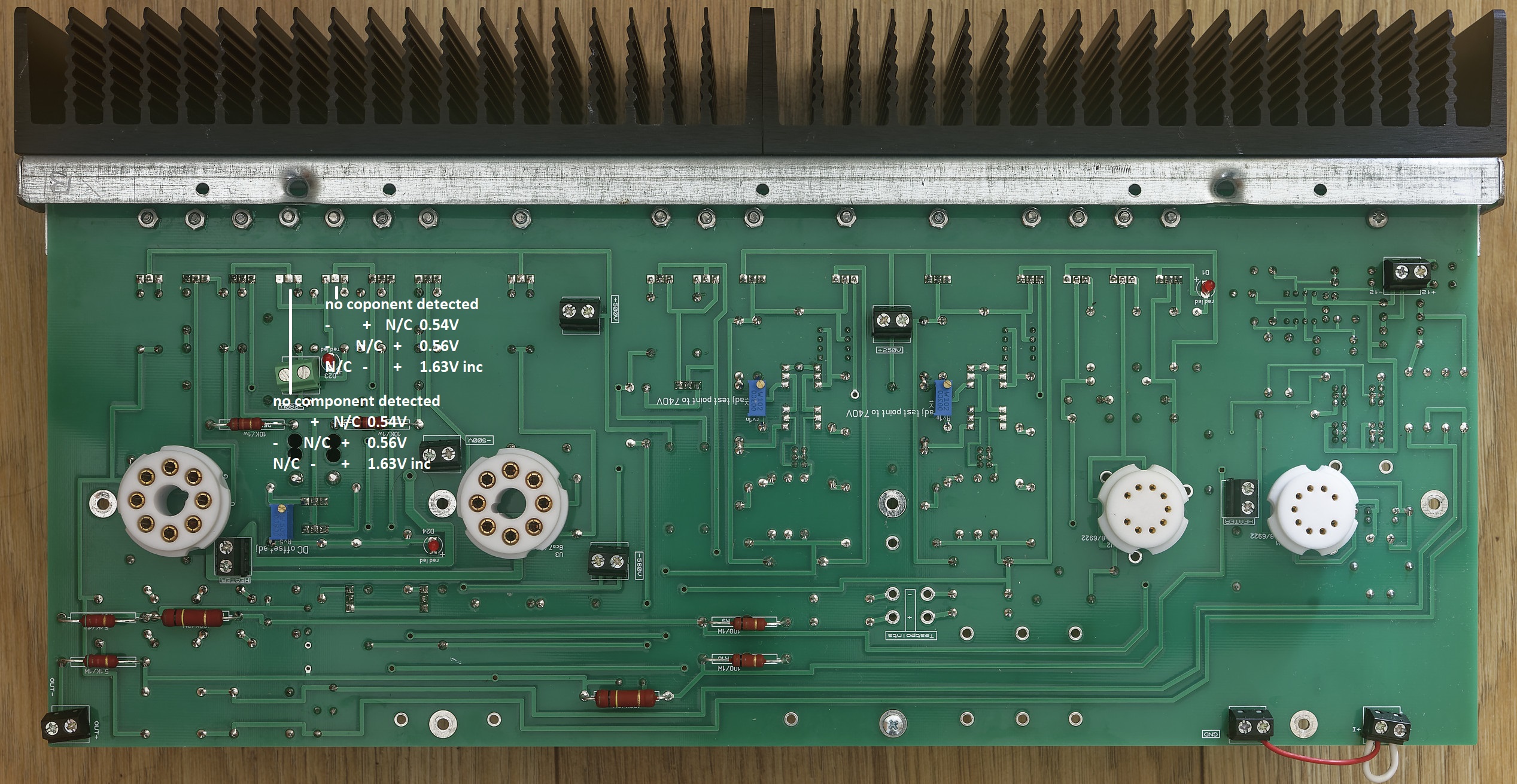
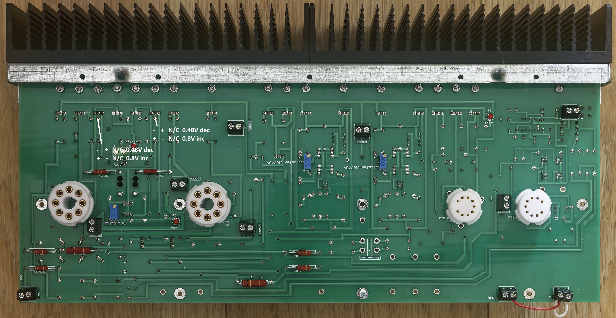
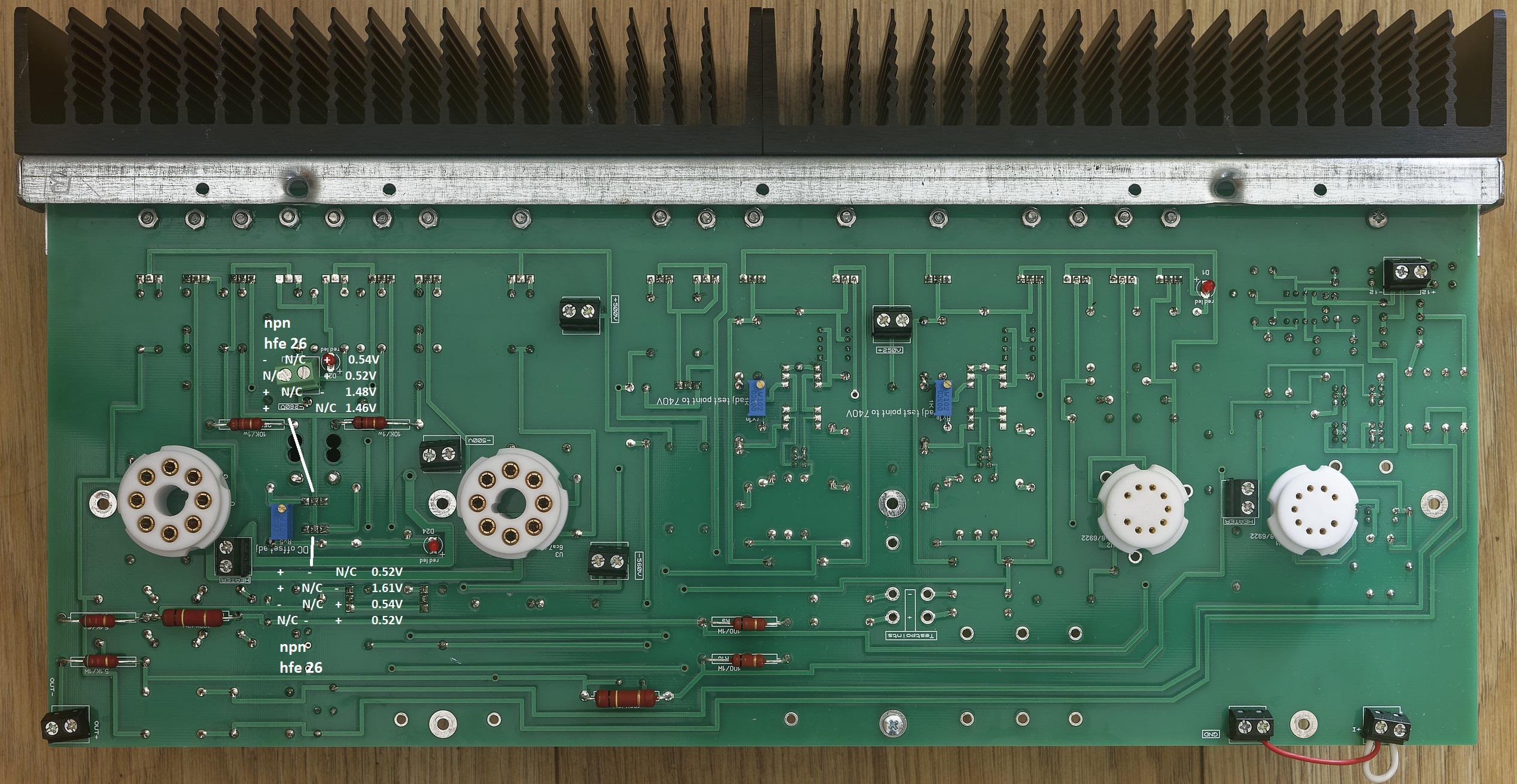
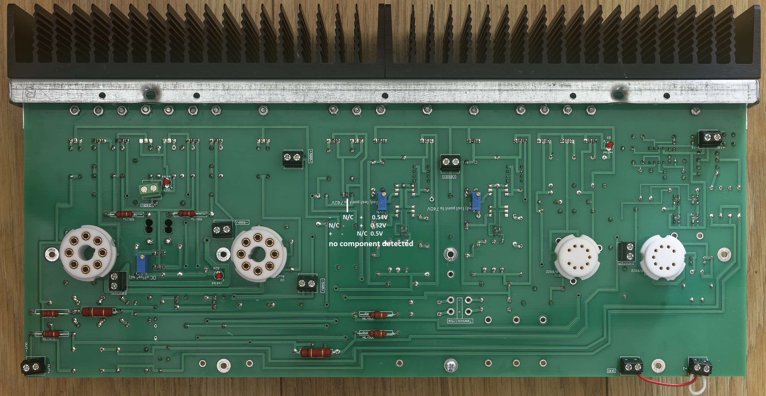
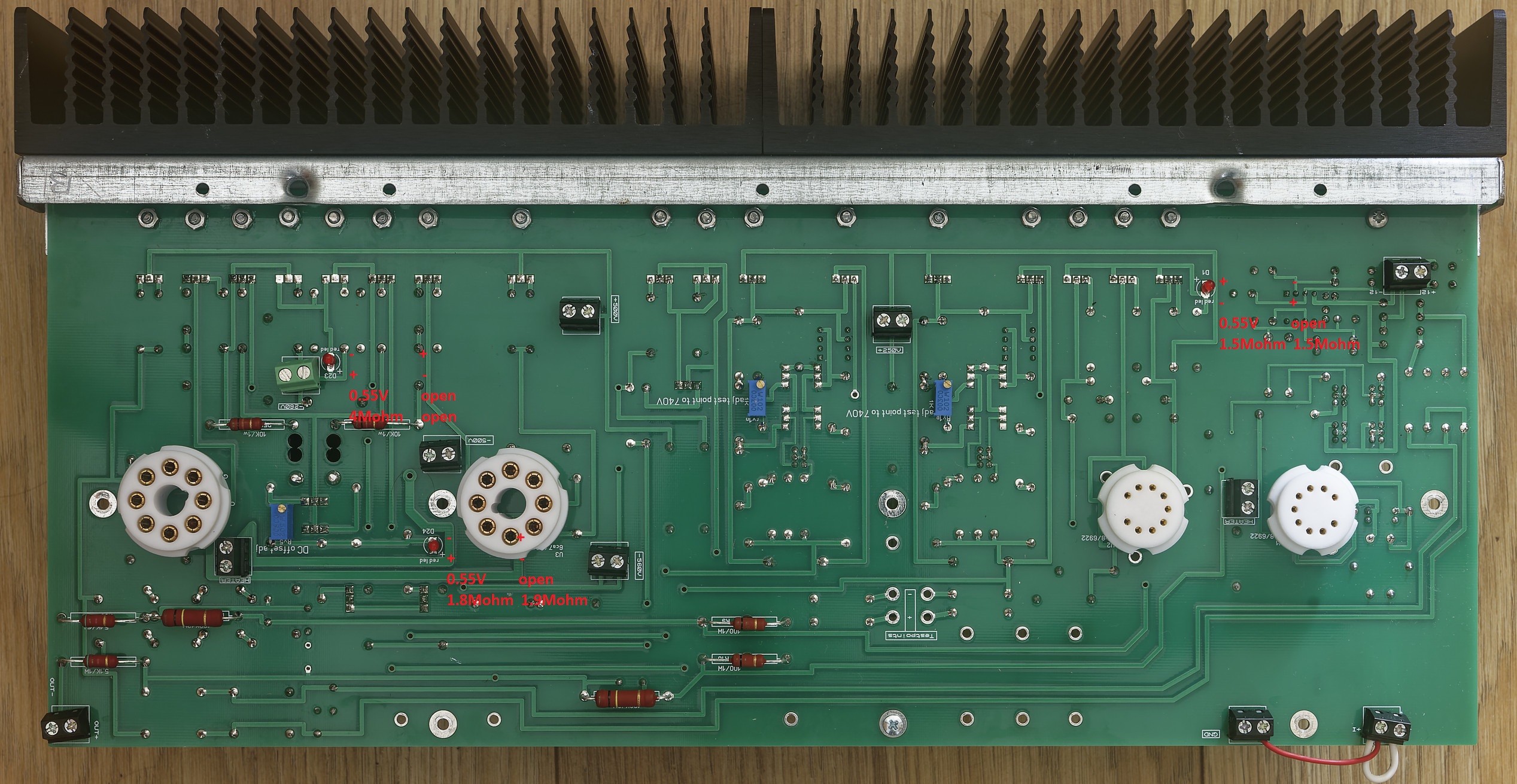
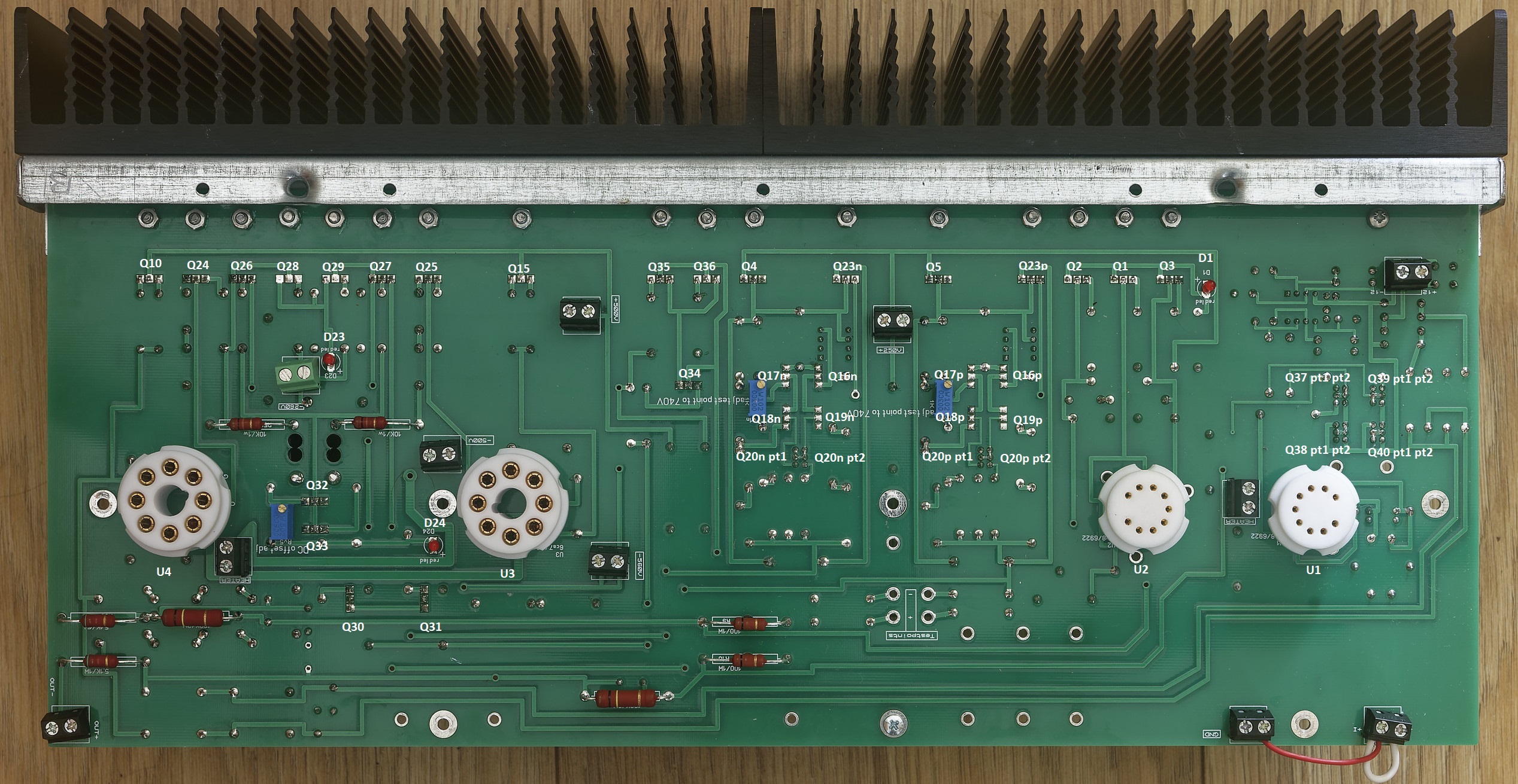
 2 points2 points2 pointsI think that is basically a vape cartridge… how does it ping and pong then?2 points2 pointsThe unofficial mostly modern T2 troubleshooting and verification guide. Weclome, this guide covers the mostly modern T2 which has the following schematic: The gerbers for the amp can be found here: https://drive.google.com/drive/folders/1r3g2TAtBUaBdiMorTWX7yYgeJ7maQbYW and the gerbers are staxt2nc3fdh7.zip The guide is intended for both pre-power on verification of an amp build, verification of voltages on power on and general troubleshooting. All tests are performed using a Brymen BM869s and peak DCA75. Using a different multimeter may effect the results slightly but you should still get similar behaviours and ball-park figures. Transistor and Diode Location Section 1. Build verification with no valves installed and no wires/volume control connected to the amp All of these checks can be performed with a multimeter from the top side of the amp board leds Checks. All 3 leds on each channel should read about 0.55V voltage drop in forward bias (multimeter + terminal/red lead connected to led + and multimeter - terminal black lead connected to led -) and open circuit in reverse bias (swap the probes around) when tested with a multimeter in diode check mode. The leds will not light from the diode test due t the current draw if the components around them. The exact forward voltage drop will depend upon the characteristics of the red led but anything significantly different here indicates a problem. 0 voltage drop in both directions indicates a short across the led or the components it connected to. check for solder bridges and failed short transistors. 0L indicates in both directions means the led has dry solder joints or is blown. using a multimeter in resistance mode check the leds D23 close to the -360VDC psu input. In forward bias expect around 4M ohms. With the probes reversed you should get open circuit. D24 is the led closest to the octal socket for the EL34 and should read about 1.8M in forward bias and about 1.9M in reverse. D1 is between in the 9 pin sockets but close to the heatsinks. This should read about 1.5M in both directions. Readings in both directions of a few hundred K ohms or lower indicate the led may have been leaky or a transistor it is connected to has gone short circuit or a solder bridge. Input terminal checks With the multimeter in resistance mode and the - terminal connected to the amp ground, and the positive terminal connected to the + input of the amp you should get about 340K and the same for the - input. Naturally expect the same results for the other channel. If significantly different suspect incorrect resistors for R94, R7 (positive input). Or R95, R8 on the - input. Output terminal checks With the multimeter in resistance mode and the - terminal connected to the amp ground, and the positive terminal connected to the + output of the amp you should get about 0.5M and the same for the - output. Naturally expect the same results for the other channel. Valve Socket Checks. With the multimeter in resistance mode and the - terminal connected to the amp ground, and the positive terminal expect the following resistances for both EL34s: (socket viewed from the top of the amp). (note the 0.5M reading may start lower and quickly ram up and the small capacitors in the circuit are charged by the multimeter). For the 6922s (socket viewed from the top of the amp) Diode Checks of transistors Note it is possible for a transistor to fail in such a way it has very little gain but still has a diode drop and so diode checking transistors is not a foolproof measure of a transistors health. But 0V drop when not expected indicates a short etc. Diode checks KSA1156 checks Q1, Q2, Q3 two of the ksa1156s (Q2 and A3) measure the same in diode mode the centre one (Q1) differs slightly. All combinations of probes and pins on a transistor result in open circuit unless otherwise shown otherwise: + indicates positive multimeter probe attached, - indicates negative multimeter probe attached n/c indicates no probe attachment. Note: for the other channel EACH KSA1156 is rotated 180 degrees about the y (vertical) axis. Peak DCA in circuit testing Q1-3 The peak DCA 75 identifies all 3 transistors as PNP silicon. The centre with a hfe or around 28 and the other two with slightly higher hfe of 30 to 31. This test is reliable, anything significantly different indicates a problem. Note it is easier to do these tests from the underside although you can hook up the dca proe hooks to something like a sensepeek weighted self standing spring loaded probe tip assembly and test easily from the top (https://sensepeek.com/pcbite-20 Diode check and Peak DCA 75 for Q23P FJPF2145 This is reliably identified as a NPN with hfe 26 and is part of the virtual battery connected to the + output side of the channel. NOTE: It has a mirror image pinout compared to the ksa1156s. Diode check and peak DCA 75 check for Q5 2SK216 This is reliably identified as a N channel mosfet with body diode and has a transconductance of 23.3mA/V. Although not part of the virtual battery it is directly connected to it. WANRING This transistor has a live mounting tab and must be fully insulated from the heatsink. A resistance check from the metal tab to the heatsink it is mounted on absolutely must read open circuit. Diode measurement for this transistor does not show a stable reading. In this case dec indicates a reading that decreases over time. The next two transistors in the heatsink row are Q23N and Q4 which perform exactly the same role and are exactly the same type of transistors as Q23P and Q5 respectively and should measure about the same I got 28mA/V for the Q4 so expect a little variance here). NOTE: on the other channel the order of the 2SK216 and FJPF2145 are reversed. Diode check and peak DCA 75 check for Q35 and Q36 FJPF2145 These are the current providers (driven by Q34) for a 10mA constant current source that feeds the input 6922s. The job is equally divided between them and they should measure the same. The DCA75 reliably identifies them as NPN silicon hfe 25-26 Diode check and peak DCA 75 check for Q15 and Q10 (10M90S) These are identified out of circuit by the dca75 as N channel depletion mosfets. However, in this circuit they provide anode current and are wired in such a way the DCA75 can not identify them and reports no component. The DCA75 should not report any shorts and the metal mounting tab is live and absolutely must be insulated from the heatsink they are mounted on. Q15 and Q10 are identically configured and should measure the same. The gate and cathodes are connected together with resistors totalling only 400ohms so the diode drop voltages will be lower than for the other transistors also unlike the other transistors all combination of probes will result in a voltage drop. The voltage drop should be the same in the forward and reverse directions. Diode check and peak DCA 75 check for Q28 and Q29 (KSA1156) These are identified out of circuit by the dca75 as PNP silicon. However in this circuit they are wired in such a way the DCA75 can not identify them and reports no component. Each should measure the same. Diode check and peak DCA 75 check for Q26 and Q27 (2SK216) These transistors do not produce stable diode voltage drops. Diode check and peak DCA 75 check for Q25 and Q24 (2SJ79) These transistors are not easy to get a stable reading on. Diode and peak dca75 Check Balance servo Q37 - Q40 (MPSA06) 4 of the MPSA06es have their collectors and bases shorted together and so can be considered to only have two pins as far as diode checking concerned. NOTE for any transistor with shorted pins only two dca75 probes were used (one to the shorted pins and the other to the non shorted pin) to avoid the dca just reporting probes shorted. Understandably ni this case the dca75 can not identify the component as a transistor and instead reports a 9.87V zener. All other transistors are correctly identified and hfe provided. Diode and peak dca75 Check Virtual Battery Q16 - Q18 (STN9360) and Q20 (MPSA06) the other virtual battery in the channel (just to the left) should measure similarly and is identically laid out. Q20 pt 1 has collector and base shorted. All 4 stn9360 should diode measure similarly. NOTE for any transistor with shorted pins only two dca75 probes were used (one to the shorted pins and the other to the non shorted pin) to avoid the dca just reporting probes shorted. Understandably ni this case the dca75 can not identify the component as a transistor and instead reports a 10V zener. All other transistors are correctly identified and hfe provided. The stn9360 are pnp and the remaining non shorted mpsa06 as npn Diode and peak dca75 check Q30 and Q31 (FJPF2145) Each transistor provides a separate 5mA current source and are directly connected to the virtual battery. With the led D24 across their base and emitter. Each is identically configured and should read the same. Dca75 reliably identifies both transistors as npn both hfe 18 Diode and peak dca75 check Q32 (on seperate small heatsink) and Q33 (FJPF2145) this forms a 20mA current source which is controlled by Rv5 and sets the DC offset. DCA75 reliably identifies both transistors as npn both with hfe 26 Diode and peak dca75 check Q34 (FJPF2145) Q34 provides control for Q35 and Q36 which creates a 10mA current source. The dca75 says no component detected. <<< IN PROGRESS >>> #include <usual_disclaimer.h> #include <usual_high voltage_warnings.h>
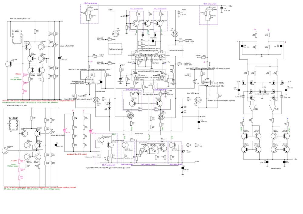


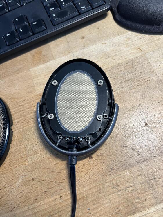
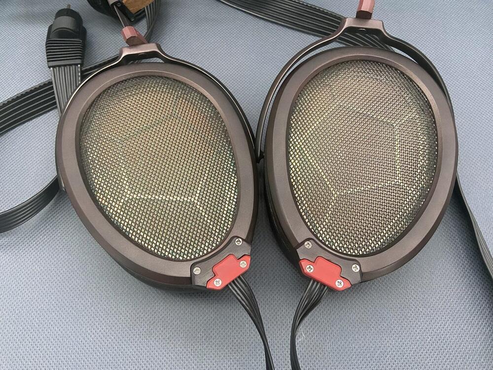
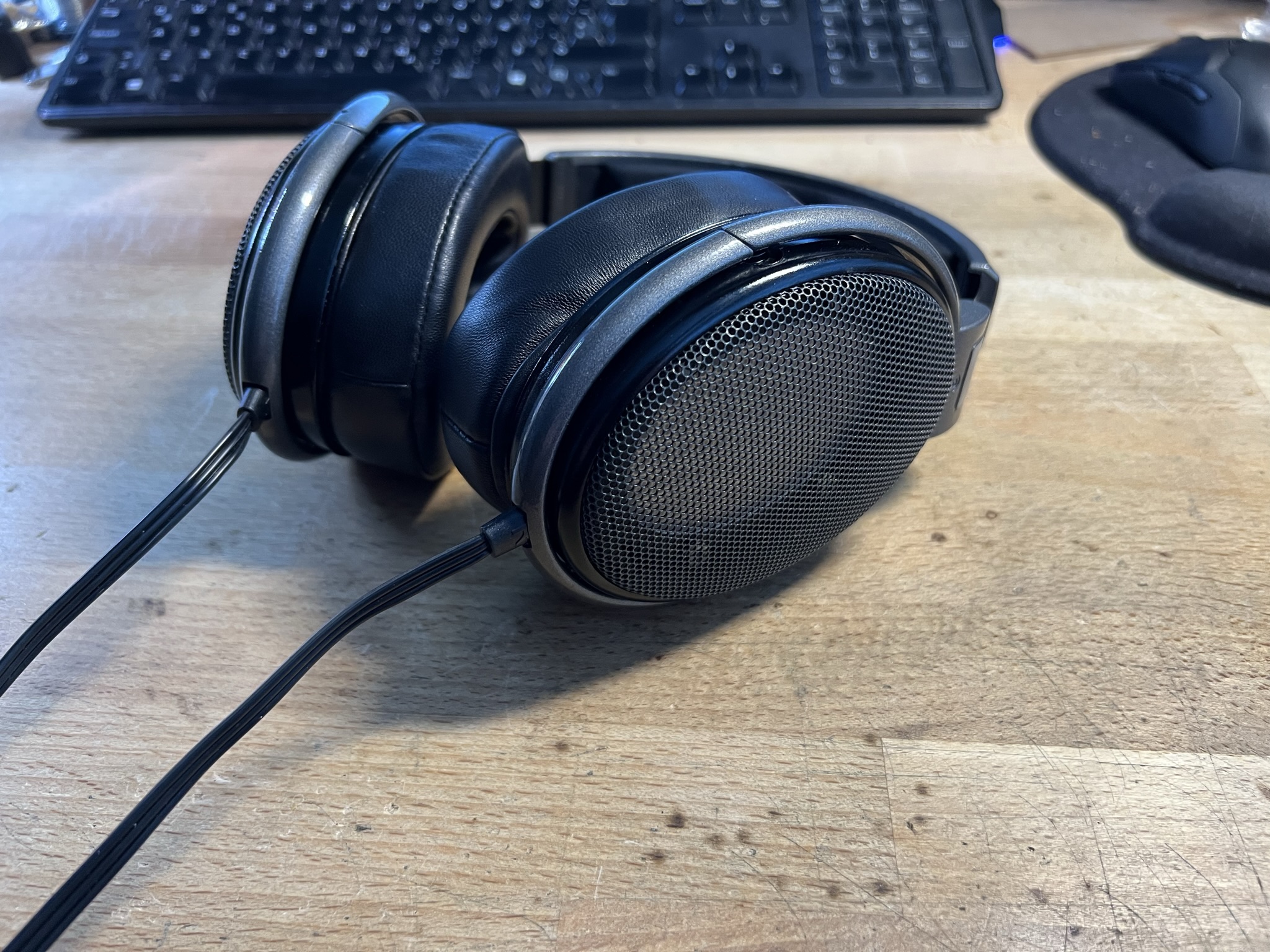
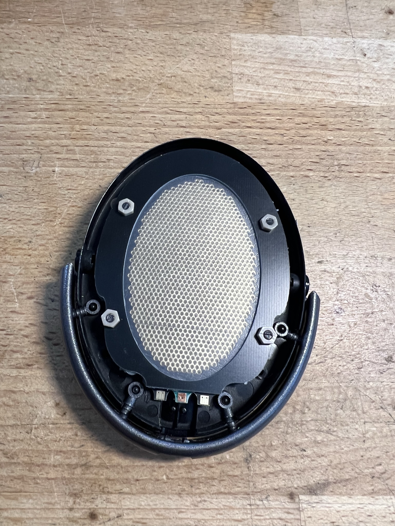
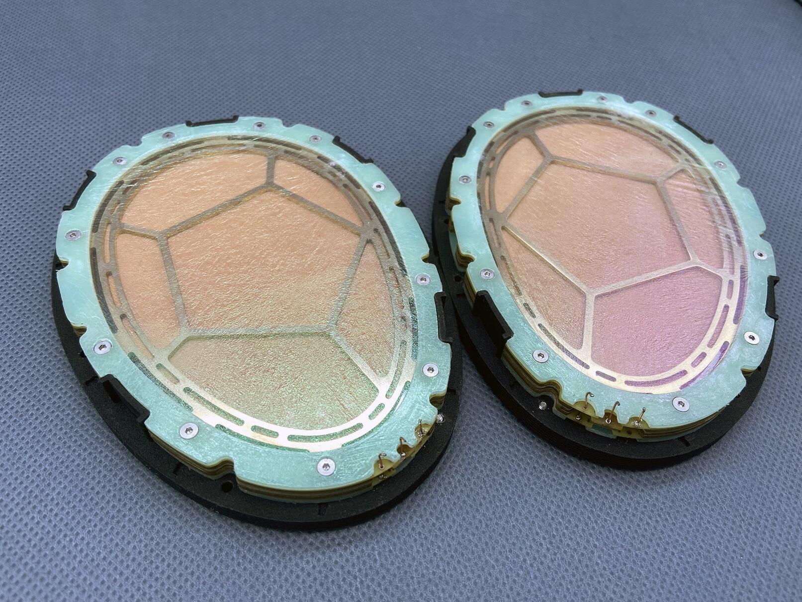
 2 points1 pointI did search but I couldn't find a dedicated thread about DIY electrostatics so in the spirit of getting the discussion started, here is something I've been working on. Well over a decade ago I bought up all the spare Sennheiser HE60 parts to assemble new headphones. The first thing to go out of stock was the main housing so to assemble the last pair, I had to adept a HD650 housing to take the HE60 drivers. Ever since then it has stuck in my head to make my own drivers for those housings and well... here is version 2.0: I bought a ratty old HD650 and completely stripped it apart. Headpad, earpads and cable went into the trash while the rest went for a long bath. First step is to make the baffle flat so a lot of cutting with nice, sharp, flush cutters. I naturally forgot to take a picture of that step... Next step was to fully measure what area I had to work with and design PCB's to match that, while maximizing the open area. The end result is three different PCB's, as they are all setup to be dual sided. One for the stators, one which holds the diaphragm and finally the simple outline which holds the dust covers and can act as a spacer. Some pics of them assembled in the housing: Four nylon screws hold the sandwich together, fixed with PEEK nuts to get extra gripping power as the assembly had to be as flat as is possible. Dust covers placed away from the stators so they don't cause any issues. Earpad side: Due to the screws, some earpad mountings have to be cut up to get the pads to fit but yeah, they are just cheap crap from China so who cares. I could cut a slot in them to try and make it fit but maintaining as much pressure on the drivers as I can is far more important. Final assembly with a King Sound cable as I have a couple of those sitting around. For the diaphragm I used my usual stock of 1.4um film and the earpads are just the cheapest leather pads I found on ebay. I have a couple of nicer ones but these are the thickest and that helps make them more balanced sounding. The diaphragms were stretched by hand on a mirror (which is my preferred way) and glued with wood glue (thanks for the tip Aumkar!) which is just perfect for this. Coating is anti-static spray which means they energize in five seconds or so which I can live with. Now for the sound... pretty damn good for something so simple and literally being the second set I assemble. Well that and zero effort has been put into sealing the baffle or just any sealing at all. I just stuck the PCB's onto the baffle and built up the stack. Overall sound signature is similar to the HE60 but not as diffused and with far more bass output. Maybe a tad too much at times as there are some oscillations that I can pickup at very high volume levels and under high excursion. I tend to go with slightly less tension on the diaphragm so that might be it. Treble is very pronounced with the thinner pads but with the ones pictured, it is just perfect. These are not forward at all and the soundstage is excellent for this size of a driver and non-angled earpads. Sensitivity is slightly lower than the regular Stax sets but still only marginally so. All in I'm very happy with the roughly 150$ outlay for these. Now this is version 2.0 but the first version used a HD58X from Drop, brand new in the box that I cut up. Same driver profile but thicker stators so the efficiency was really bad plus the stators had full solder mask on them. Now I'm out of the spacer PCB's for the dust covers so next time I order PCB's, I'll make another set. I also have some diaphragm spacers which would work well for normal bias as I've always wanted to mess more with that.
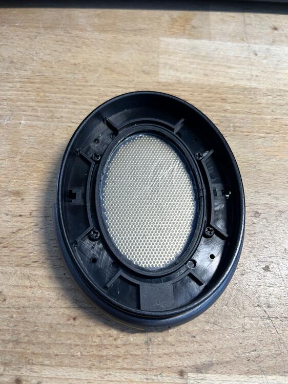

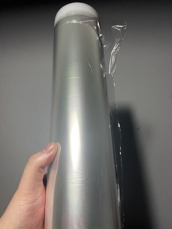
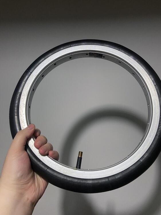
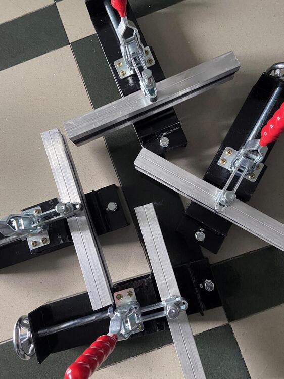
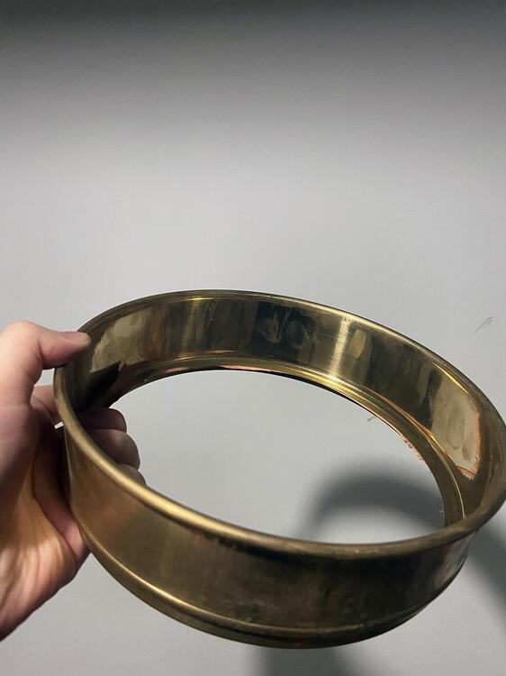
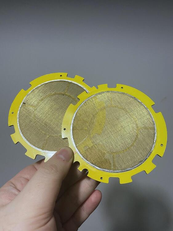
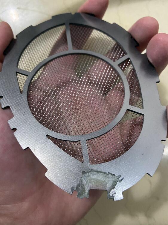
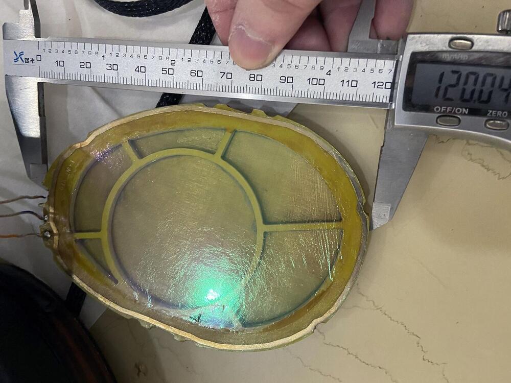
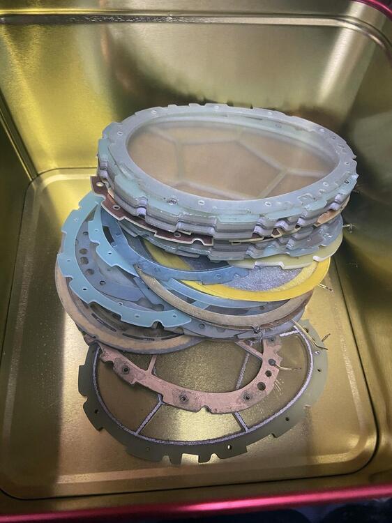
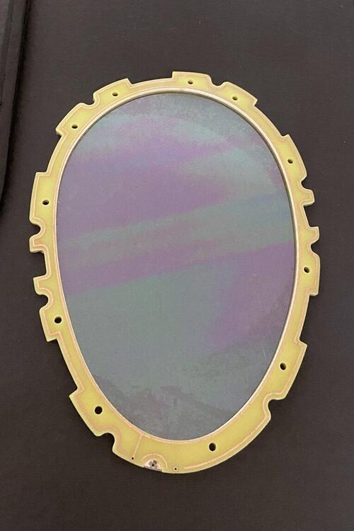
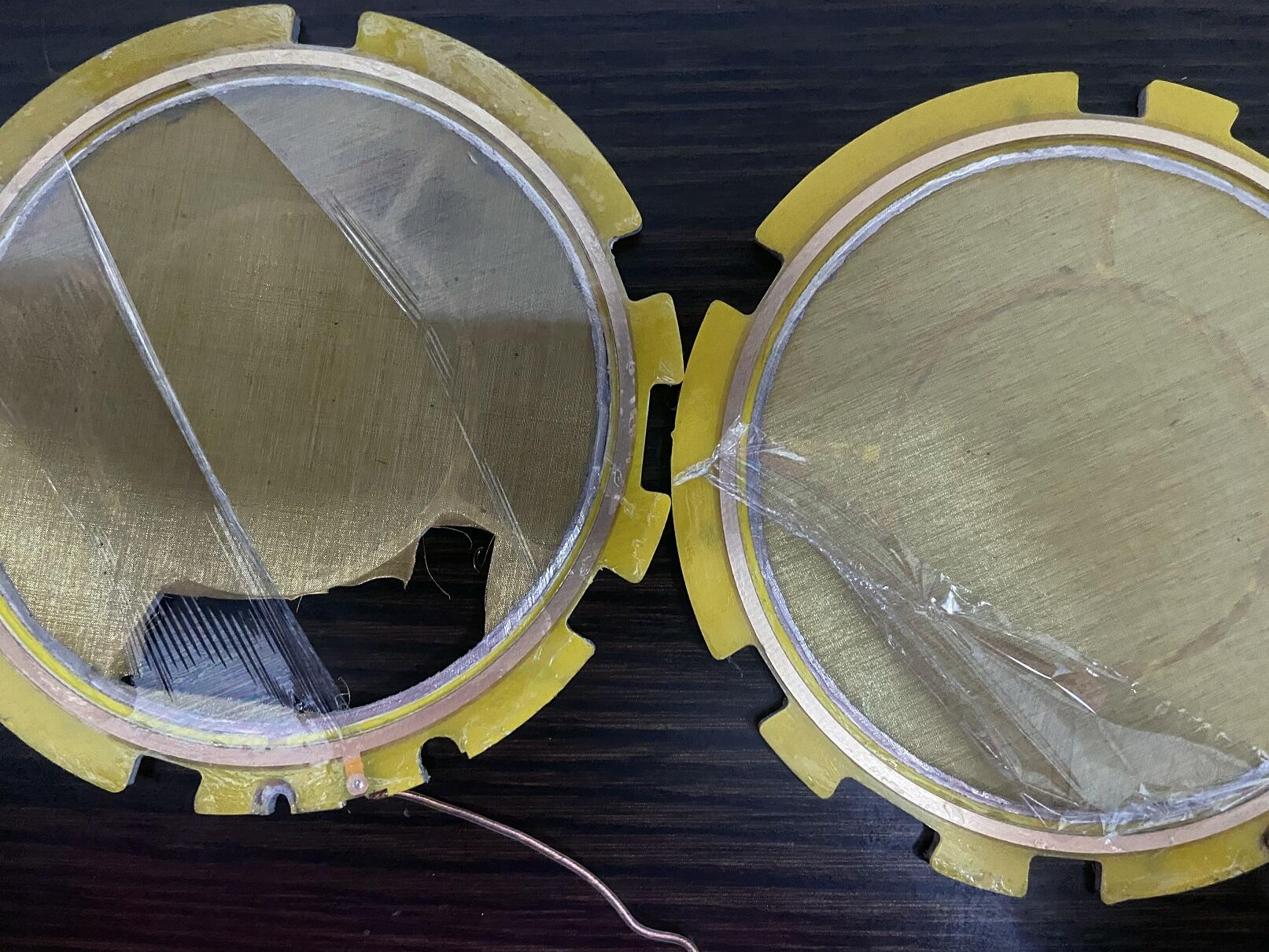
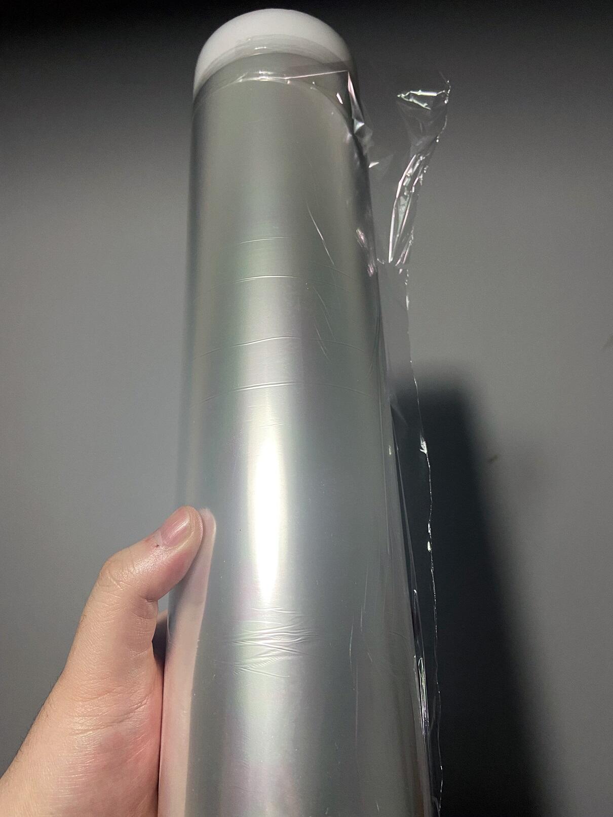
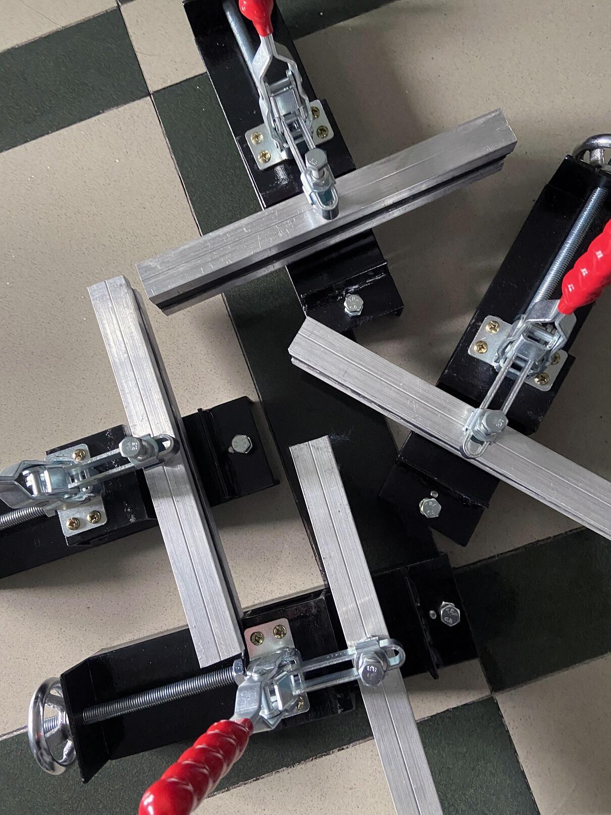
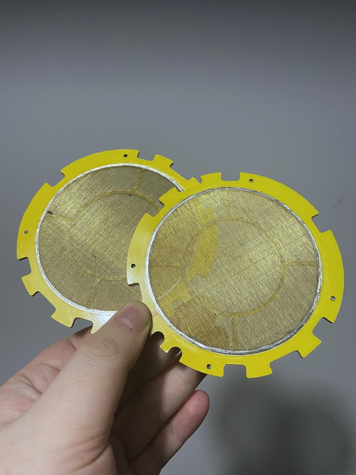
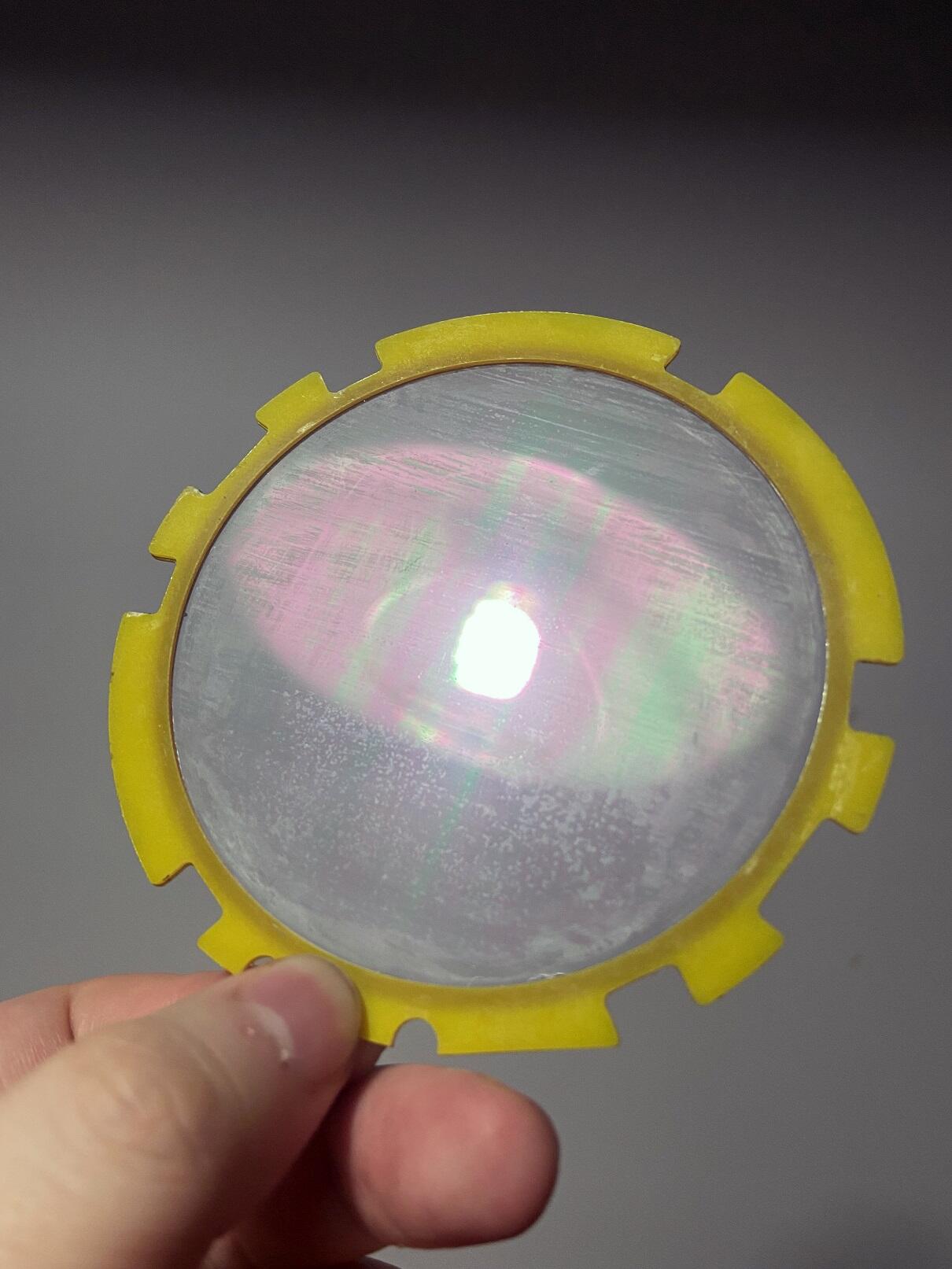
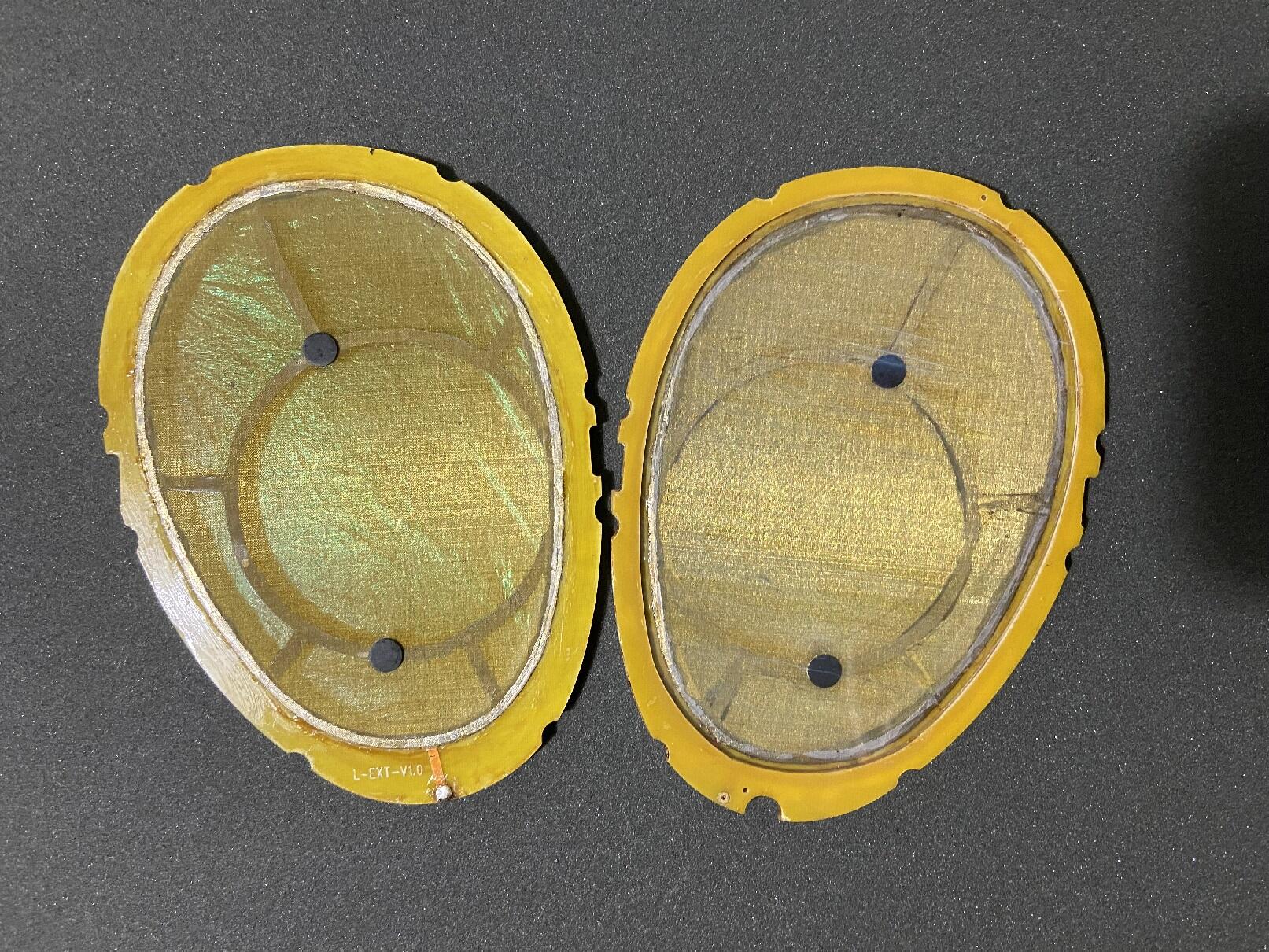
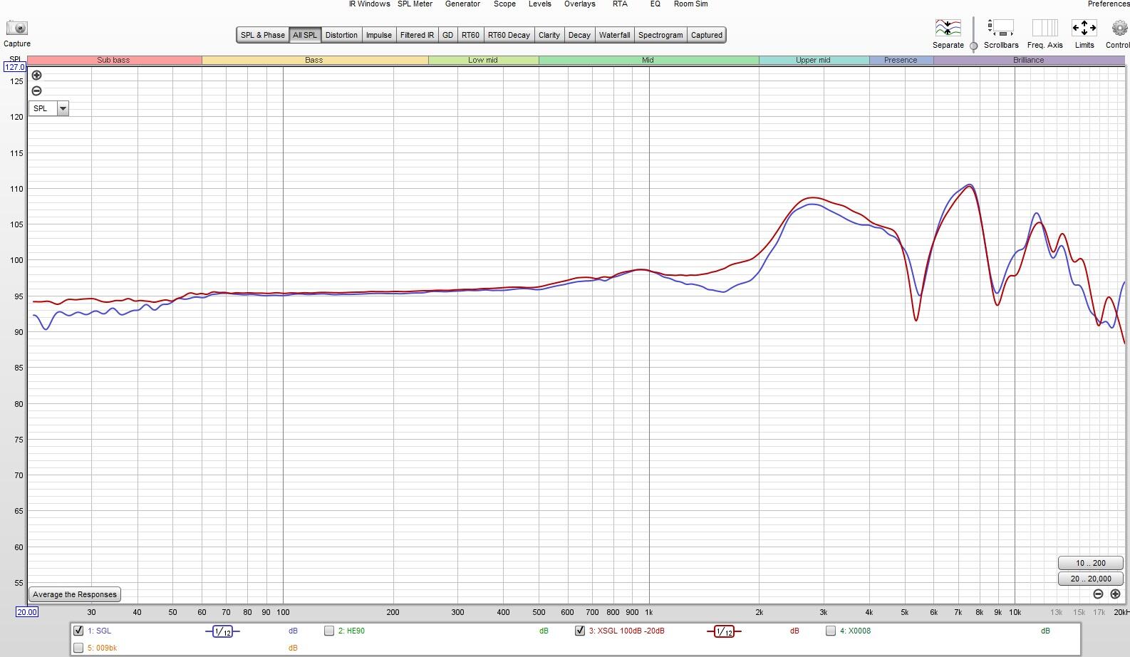
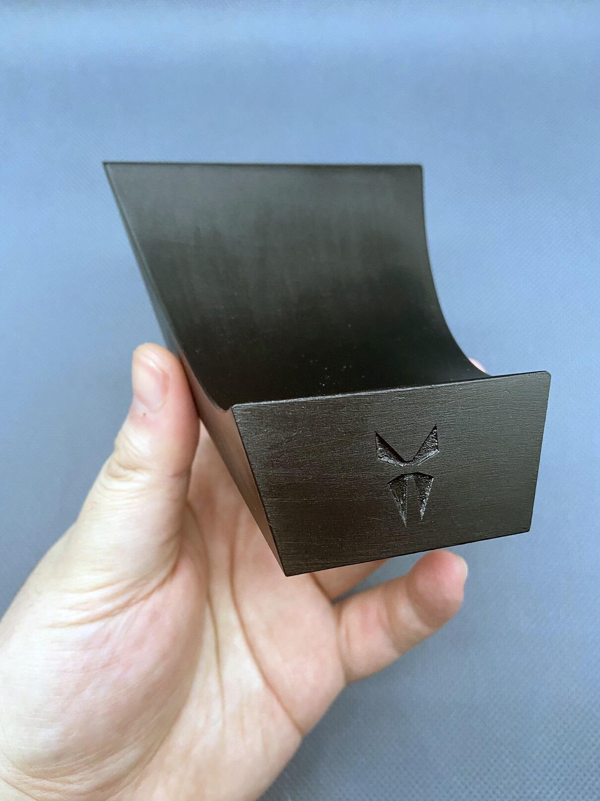
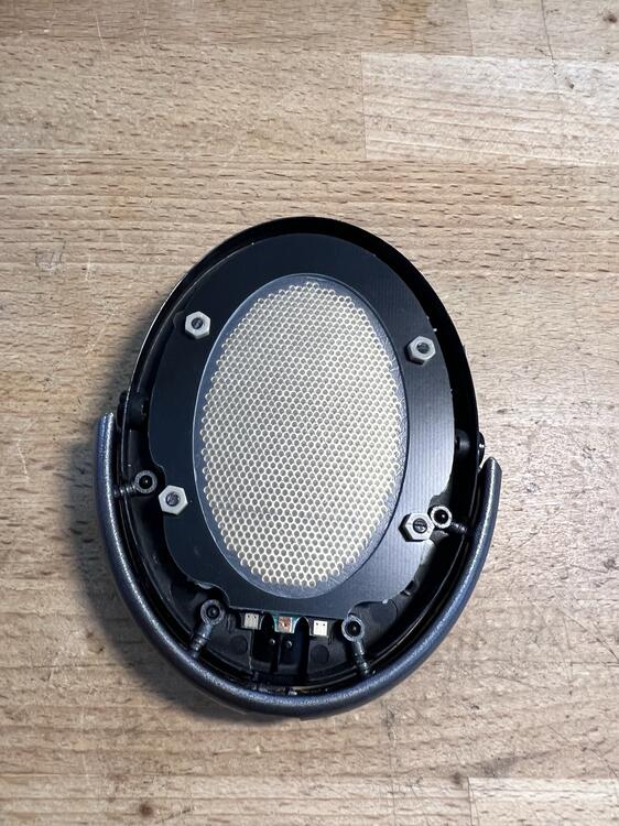 1 pointIt started with repairing a badly damaged shangri la jr driver 2 years ago, I almost rebuilt the set from the diaphragm to the stators,and of course the dust cover😦 The first thing I discovered is that the 'nano-technology' used by hifiman actually comes from the covering used by indoors aircraft model enthusiasts,the name is OS film and it is still available on ebay or https://www.indoorffsupply.com/shop/os-film-25ft-roll-1 the driver of the hifiman estats is completely glued which is similar to the early stax lambdas, but hifiman glue is significantly worse...after opening the driver i found that they only use OS film for their dust cover, the diaphragm is another PET film ~ a little bit thicker but with much better strength. In order to repair the diaphragm, I found a seller on Alibaba who can provide samples of Toray PET film with thickness below 2 microns at an acceptable price,and use the inner tire stretcher to stretch the film like any other diy estats ,Then test it with a 10" subwoofer and minidsp umik-1 to find proper F0. conductive coating is another serious problem,I've tried quite a few methods including antistatic agents like licron crystal, ANTISTATIK100,floor cleaner,carbon-based coatings such as graphene, and alcohol-soluble nylon, even tried nano-silver wire solution and metal evaporation...Some of them are sensitive to humidity, some arcs,some are ridiculously expensive, some have uneven surface resistance distribution, and some are sensitive to temperature changes. Yah~ finding the proper conductive coating is the most difficult part especially for a layman. unexpectedly, I tried to search for hifiman patents, hoping to find something useful... here's a patent showing that they used some kind of metal oxide nano particles as conductive coating for their estats. emmm,very interesting...🙄 By consulting with chemistry professionals, I decided to try a solution called ATO (antimony doped tin oxide), there are many antistatic agents I have used before have ATO ingredients though. I got some ATO alcohol solution at concentration around 10~15%, it works really well, and coating appearance is somewhat identical to hifiman diaphragm! The last thing is to repair stators. hifimans probably use #150~300 brass mesh and solder their edges to a 2mm thick aluminum base plate PCB board, then glue the rest of middle part. I've tried tensioning those brass mesh with embroidery frame and manual screen stretcher,but it is not tight enough to stretche brass mesh in this way, the mesh itself is too strong to tighten it up... then I found some brass sieves with different meshes on taobao and these machined copper screens are perfect for making DIY mesh stators... after everything's ready,i desoldered OG brass mesh, cleaned the copper foil, applied low temperature solder paste, and carefully soldered the new brass mesh with a heat gun. During the process of repairing shangri la jr, I started planning to make some bigger mesh stator estats... of course,the target is its big brother shangri la SR😈I received a set of the first batch of shangri la sr made in 2016,here is the headphone inside,yap~inherited the tradition of hifiman with such horrible workmanship...😱 however,SR sounds not as technical as the X9000 though,but with more pleasant and passion. SR uses 3mm thick aluminum base plate PCB instead of 2mm on JR version,2 black things in the middle are to prevent the diaphragm from attaching stators,The D-S gap is around 0.7~0.8mm(thickness of glue included) which is identical to JR version,active area is close to 6400mm² ,that is pretty large diaphragm size for a commercial product though,but less 5300mm² of area on stator allows air to pass through. I tried to use the 3mm FR4 board as mesh holder at first time,however,mesh stator disassembly is not an easy job...therefore,I changed to use 1.5mm brass plates as the mesh holder and glued the copper mesh to it , brass mesh is also replaced with higher # red copper mesh for more convenient adhension. I spent most of time adjusting the tension of the diaphragm and finally found the tension needed for F0 similar to OG SR ,the clone driver has a slightly enlarged diaphragm(6839mm²) ,0.73mm fr-4 pcb spacer, and everything is screwed to the housing cover. The frequency response of clone and SR are generally similar,but the sensitivity difference between the two is about 1.5dB actually,SR is more diffused...clone one sounds a bit more clearer. SR has obvious recession between 1-2kHz,it may be caused by a sealing problem in the space between the driver and the earcup.... It's unlikely to be solved without EQ, but it doesn't sound as bad as it looks from the graphics. one more thing... Every shangri la must have a throne , so I made one for my mutation🤣
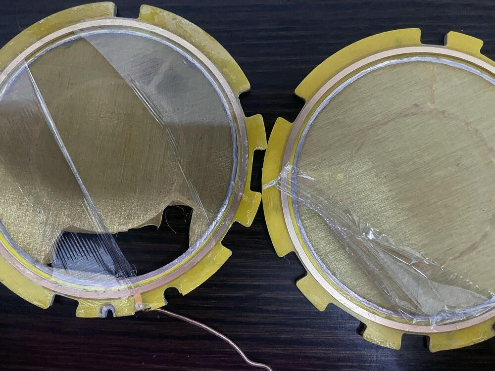


 1 pointI’m out of practice steaming milk (the Bellman is nothing like a real steam wand), but it’s nice pulling a latte together so quickly.1 pointI would also check for HV breakdown as there is continuity and then there is continuity at high voltages.1 point1 pointUsed the laser and started no forest fires. The fume extraction system I ordered comes from Canadia for some reason, so the dog sleds should have it here in 8 weeks. c28c7dcecc0243b89db8031ea145f13a.mp41 point1 pointHipster avocado toast with bacon and (poached)egg. Smoked duck sandwich
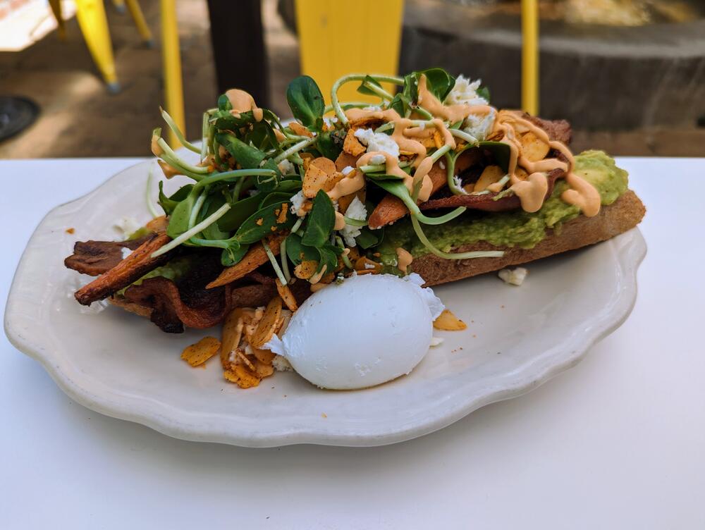
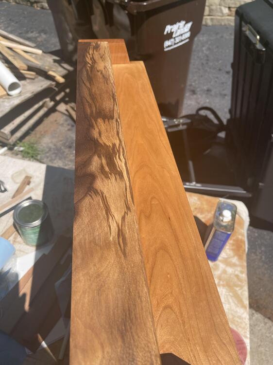
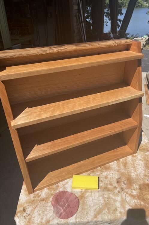
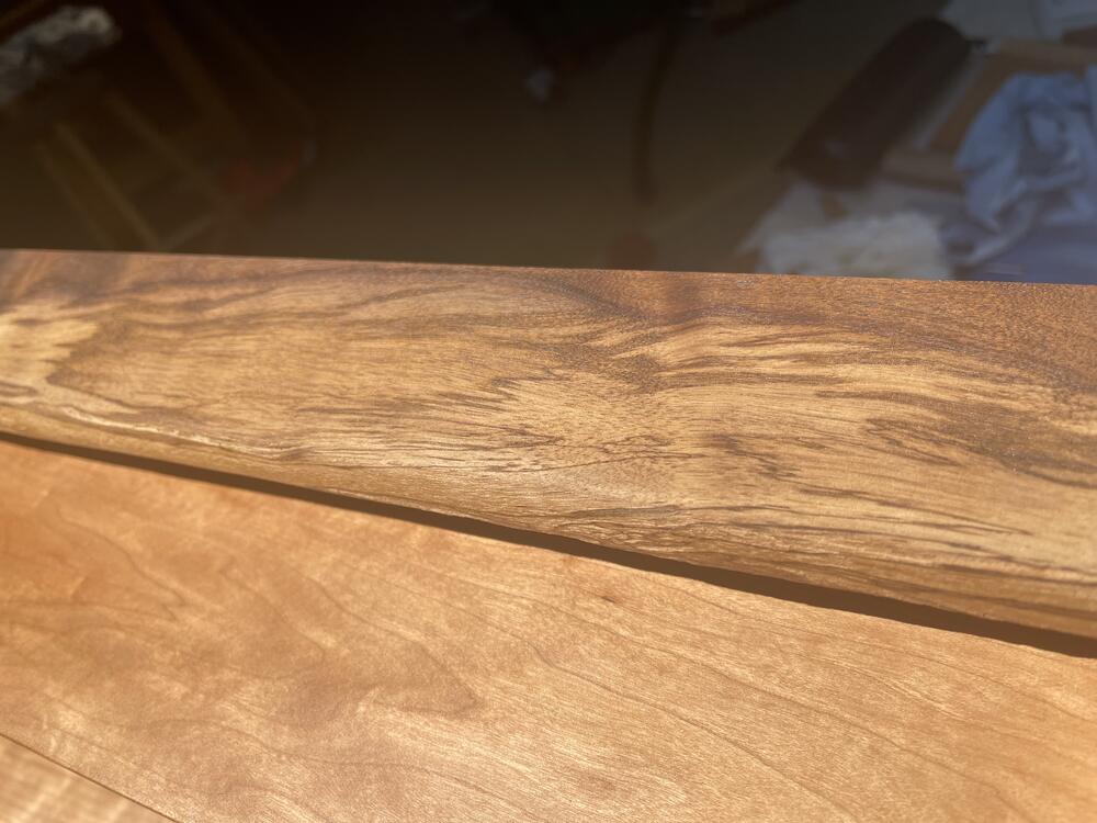
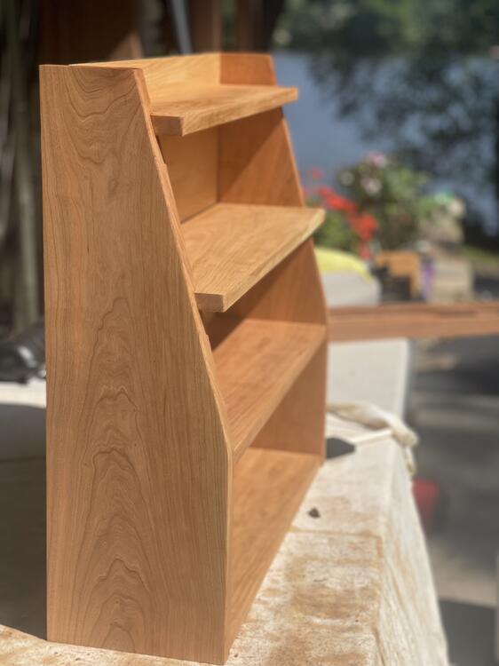
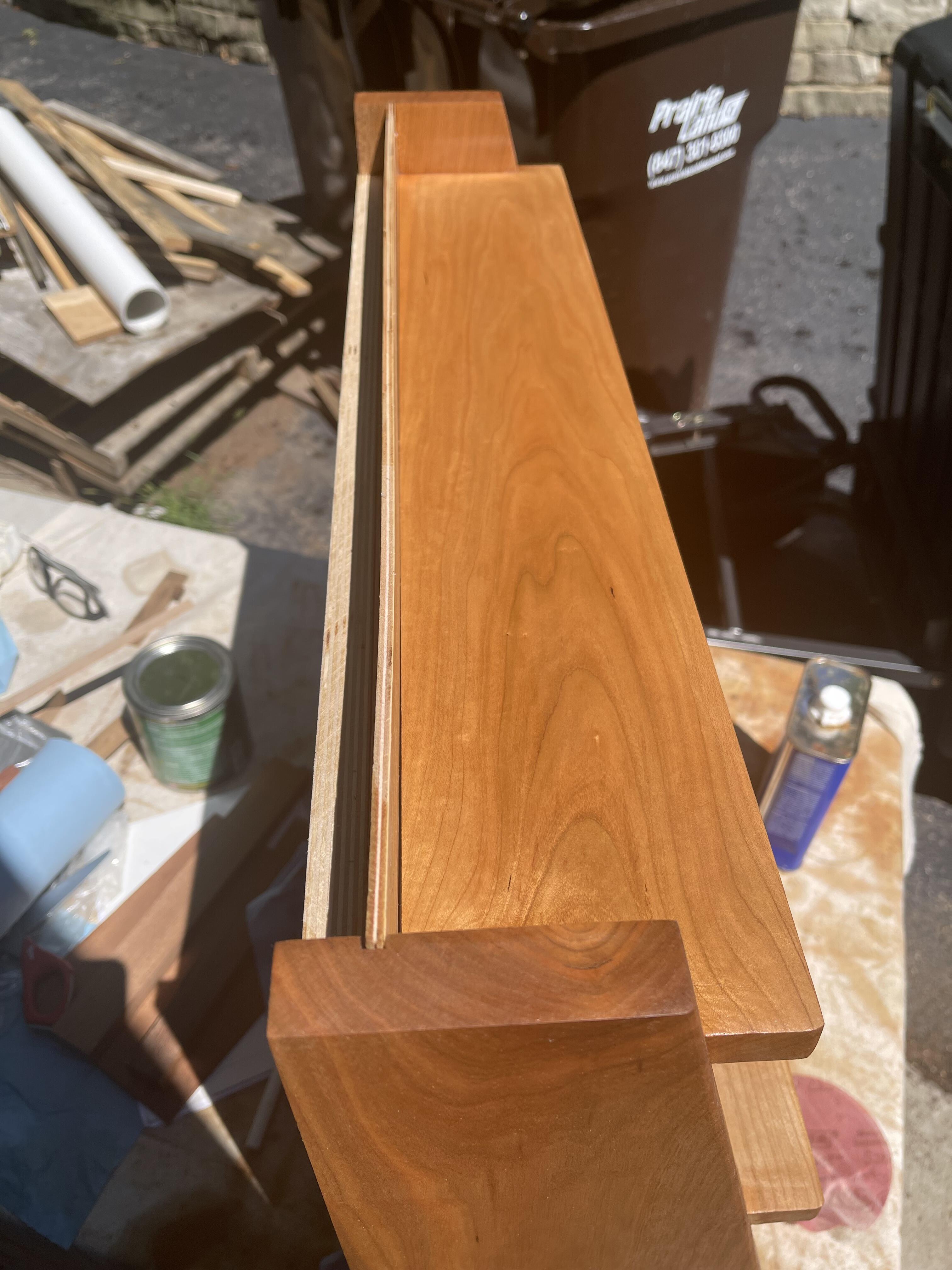
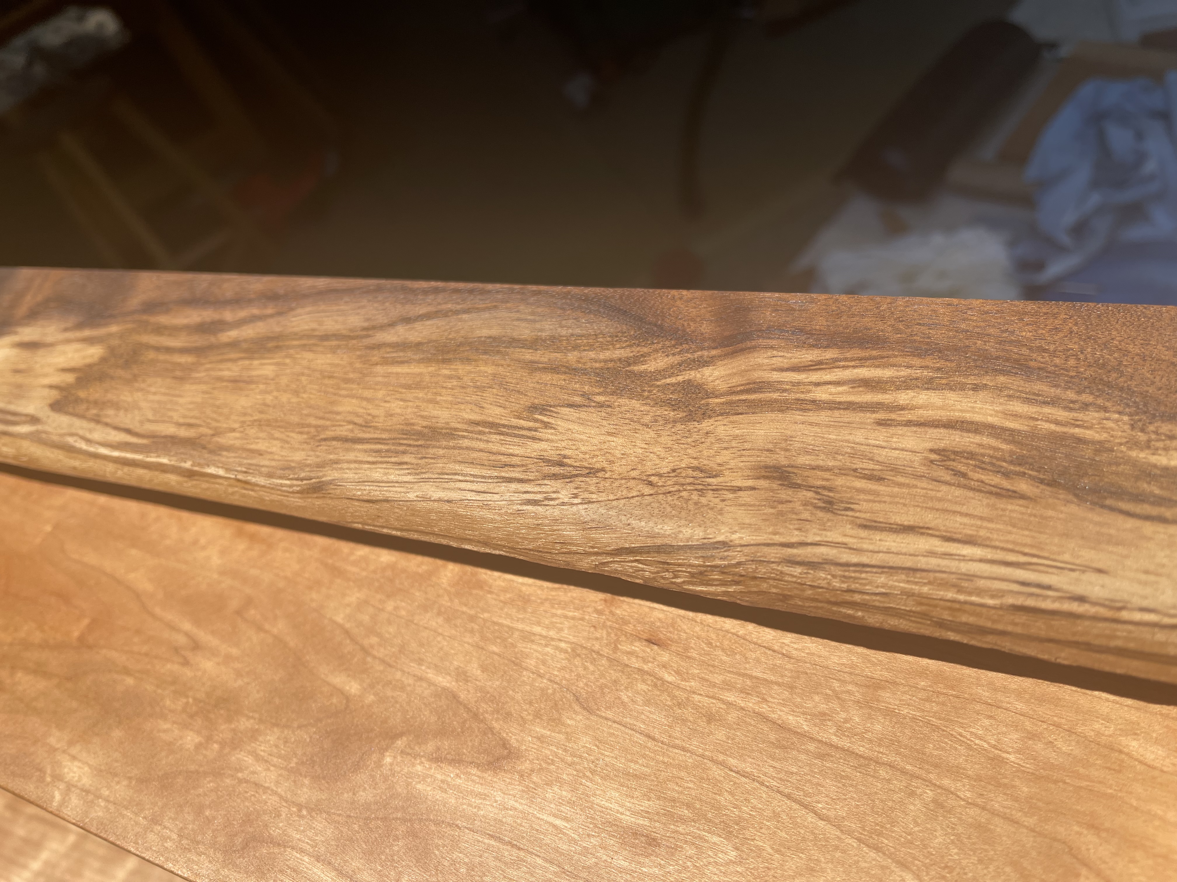
 1 point1 pointI am at the phase of the project where I am trying to hide my design flaws. At this point the top of the cabinet has exposed cherry plywood that I want to hide. Tried a first fix with the left over walnut from the drawer front but it was not long enough to run across the whole top or thick enough to recess all the way into the gap. I cannot decide if I like the wood, or the design, but do not want to mess with a whole new cherry top to cover the plywood and endgrain.
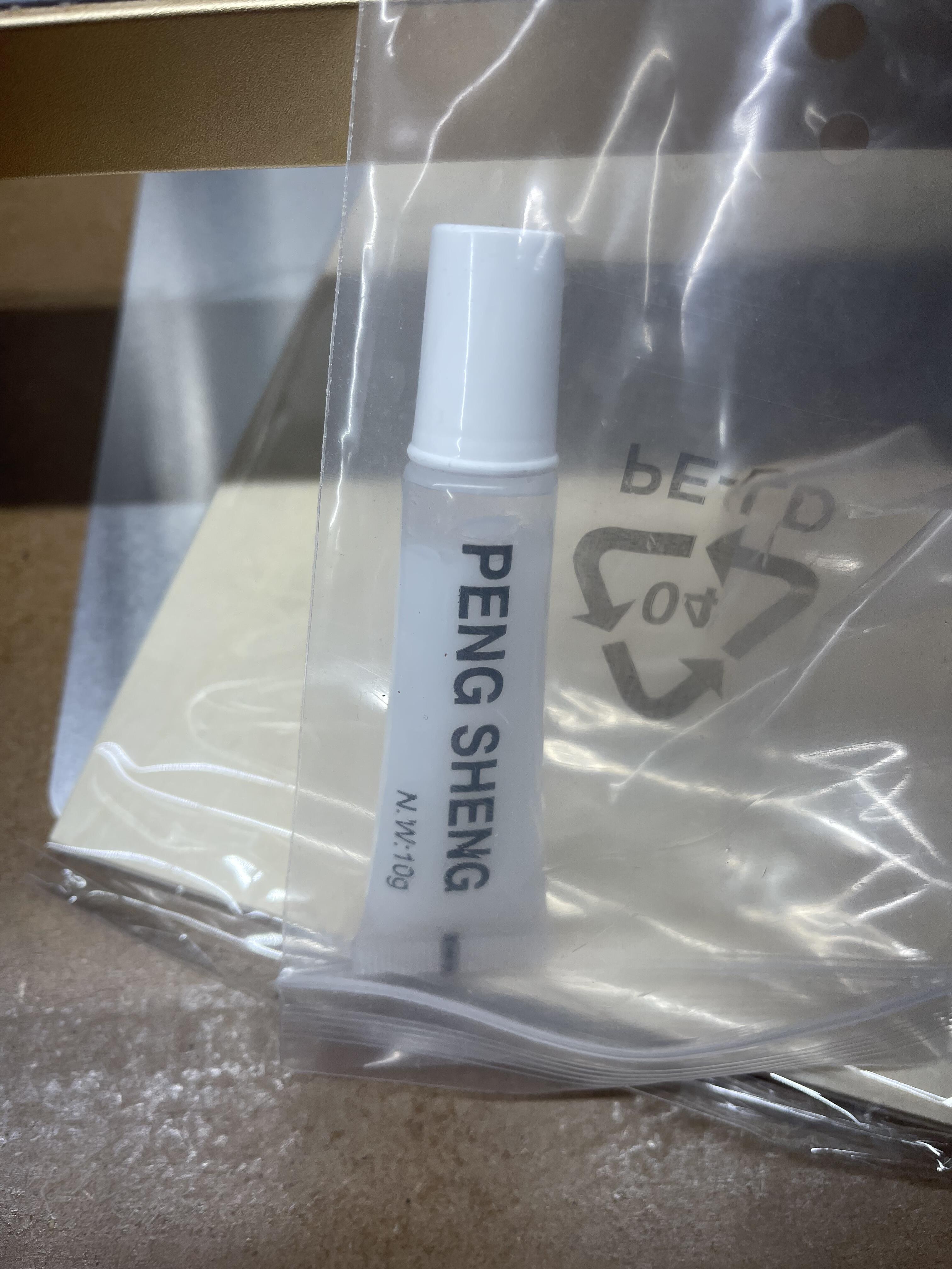
 1 point1 point1 pointI recently found out that they are considered portents of war in ancient times:1 point1 point1 point1 pointThe cleat is baltic birch and I added 2” screws into the shelf aligned with the cleat. Did a couple coats of finish today while finally building the XTool D1 Pro. Only now realizing I have no idea how to make it work or where the tube of Unicorn Semen is supposed to go, as it is not discussed in the manual.
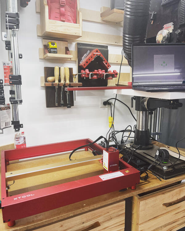
 1 point1 point1 point1 point1 pointGood afternoon Yountville But first we'd like to thank our sponsors, Sotherby's International Realty, so don't forget to rush out and buy a house after the concert. Now some classic rock, with The Fog City Swampers (And the good people of Yountville) Who were also moved to dance by the end. .


 1 pointThis is our raclette source
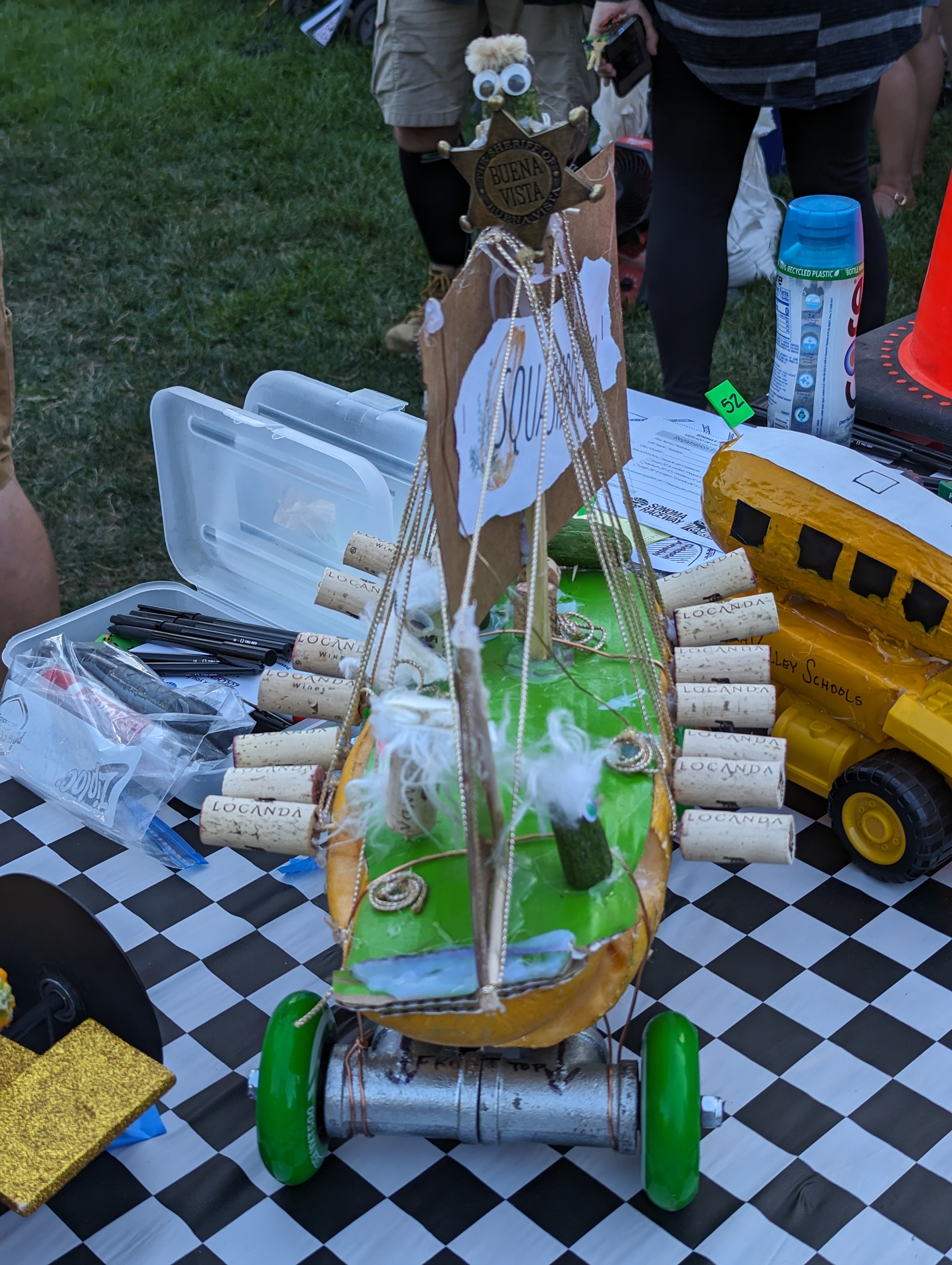
 1 point0 pointsAttended There were plenty of contenders, In all three classes. With "best in show" going to "Squashbuckler" and then it's on/off to the races, full of drama and excitement! See for Yourselves!


 0 points


Important Information
By using this site, you agree to our Terms of Use.