Leaderboard


Popular Content
Showing content with the highest reputation on 08/19/23 in all areas
-
5 points
-
4 points
-
3 pointsI don’t know how the links come out of this (looks like pin and collar, but isn’t, at least not a version I can seemingly remove), but an original beads of rice just about fits me on my Seamaster Cosmic, fresh from a service. I think it looks pretty great. It wears wonderfully: like an extra thin vintage DateJust. It rattles and is perfectly comfortable. It will get a lot of wear in the spring and summer, at least once I get it sized.
 3 points
 -
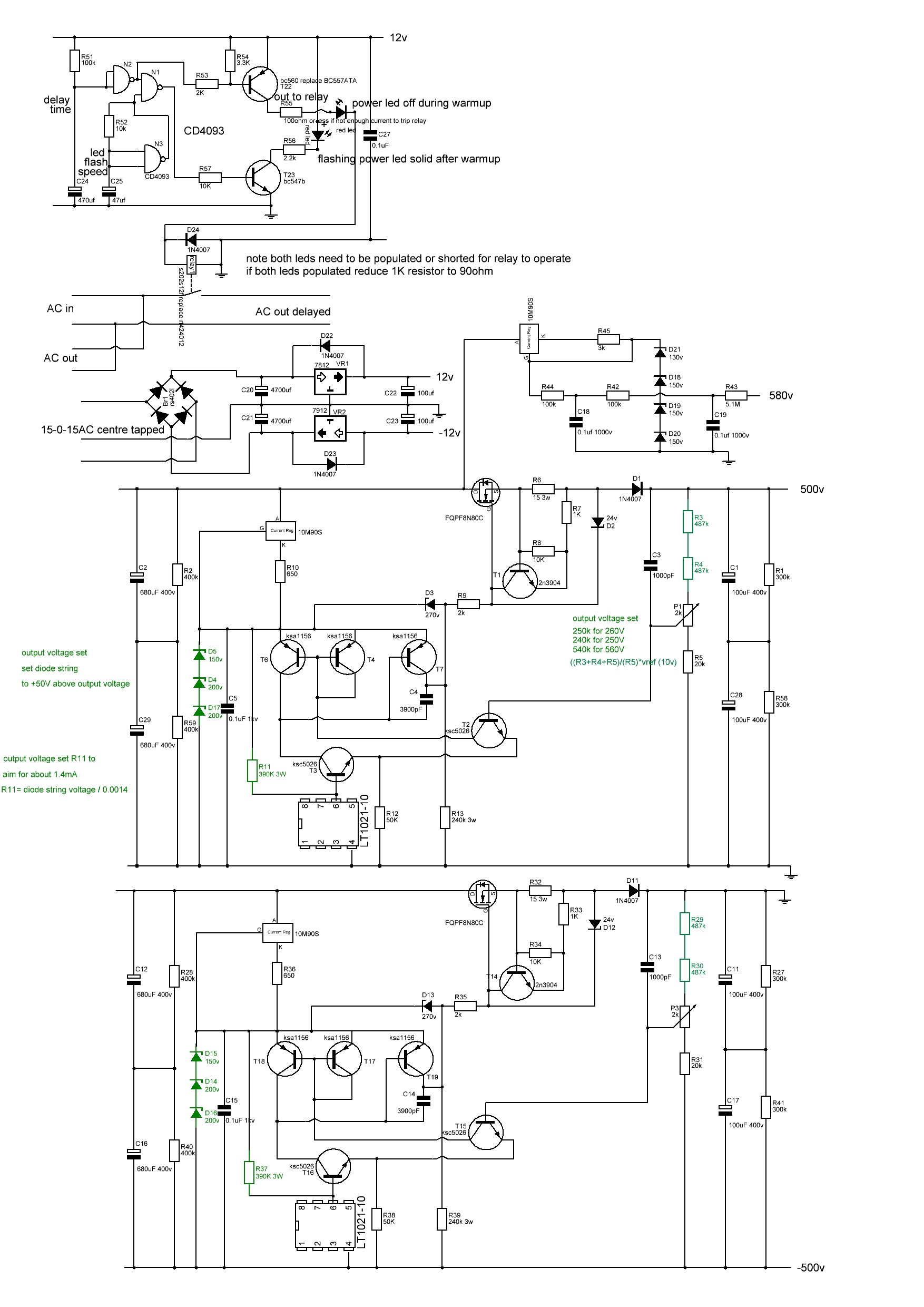
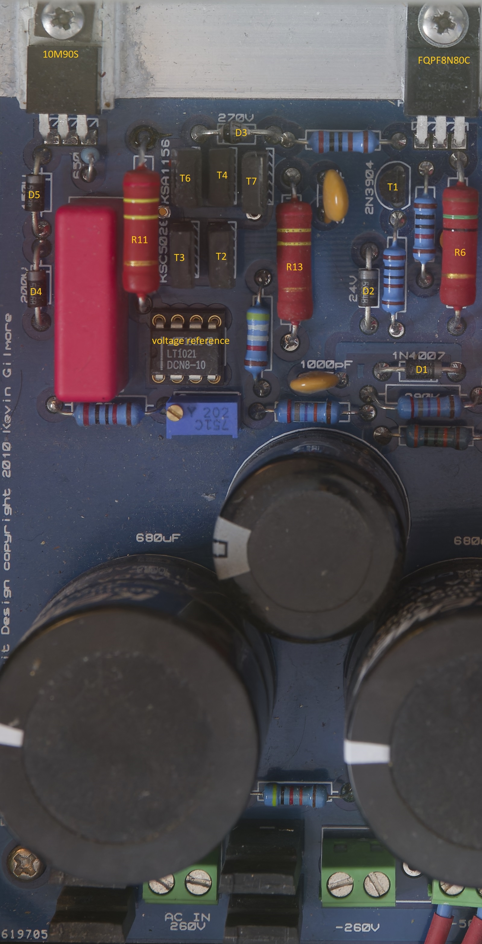
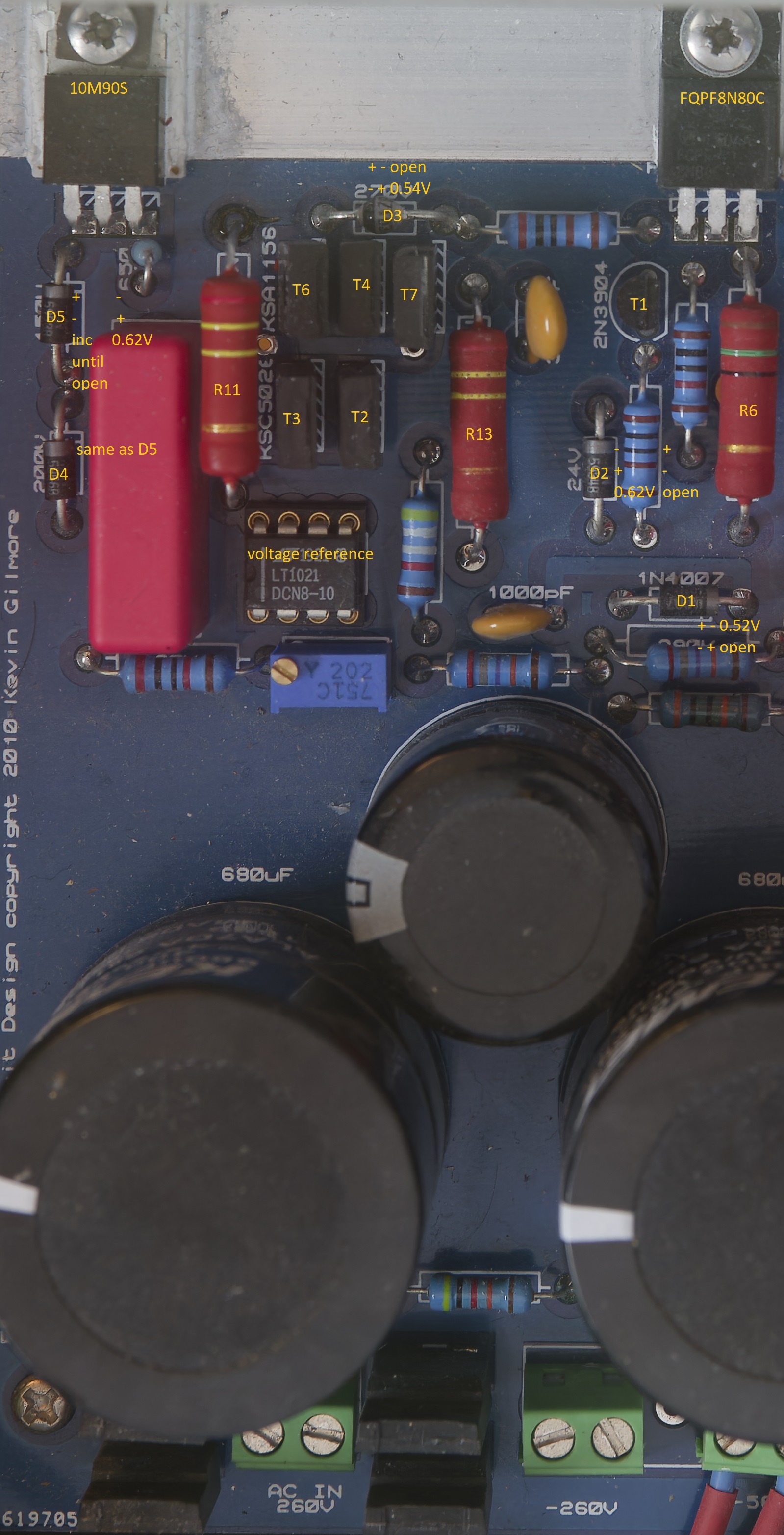
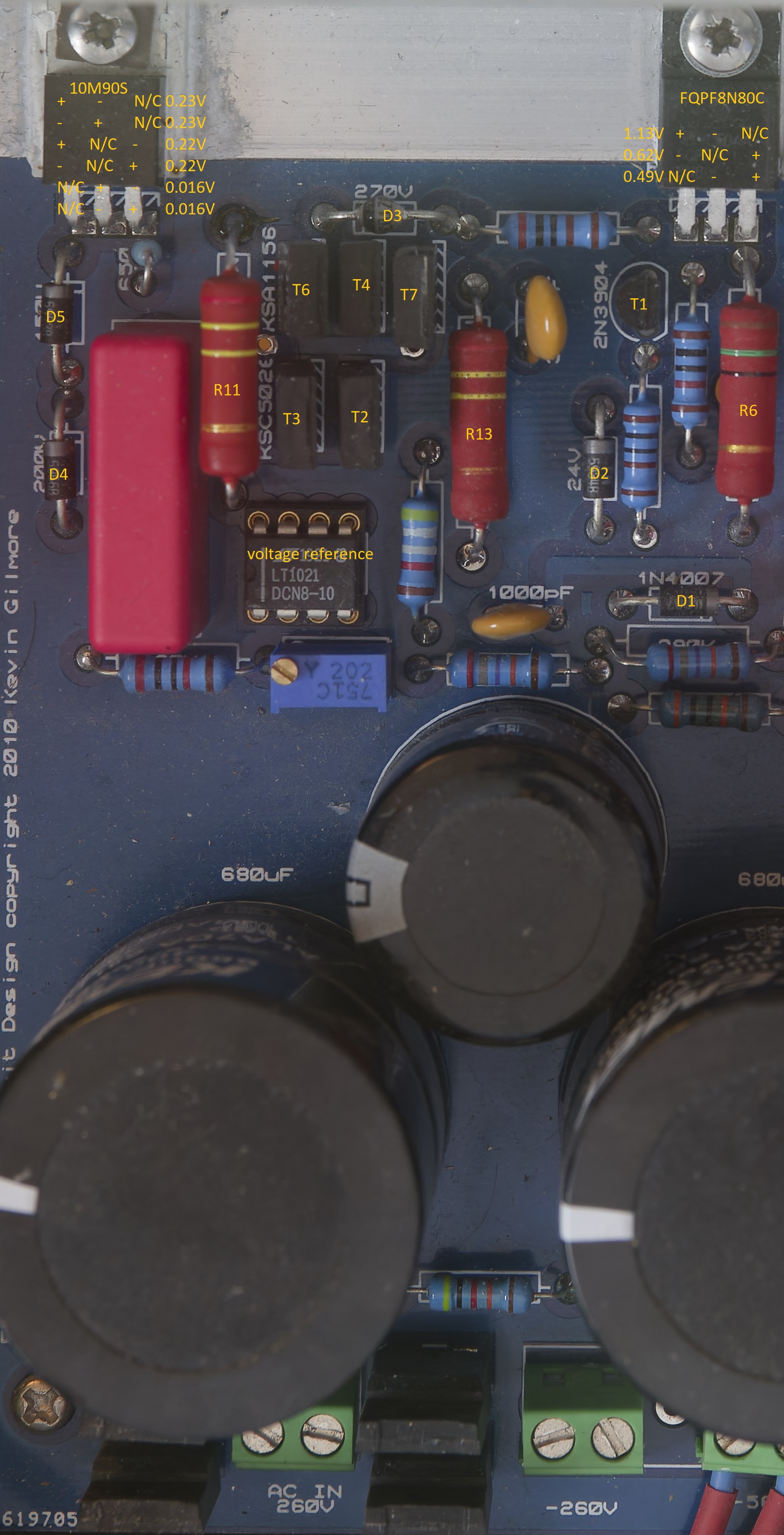
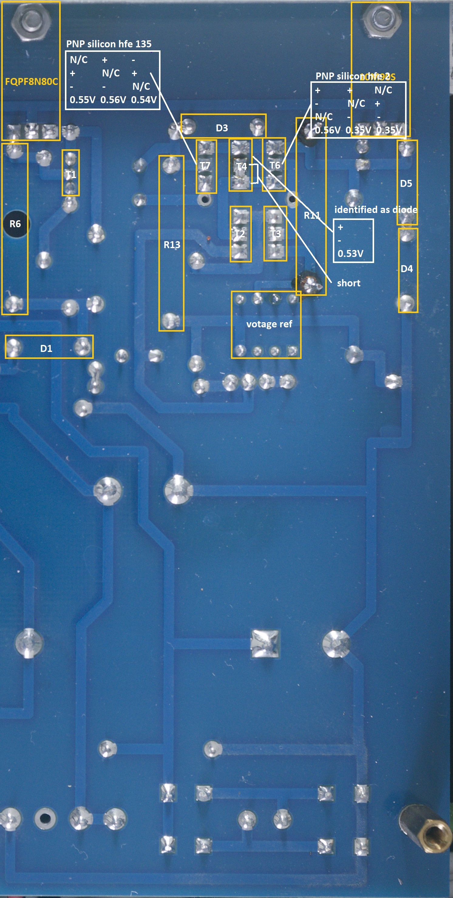
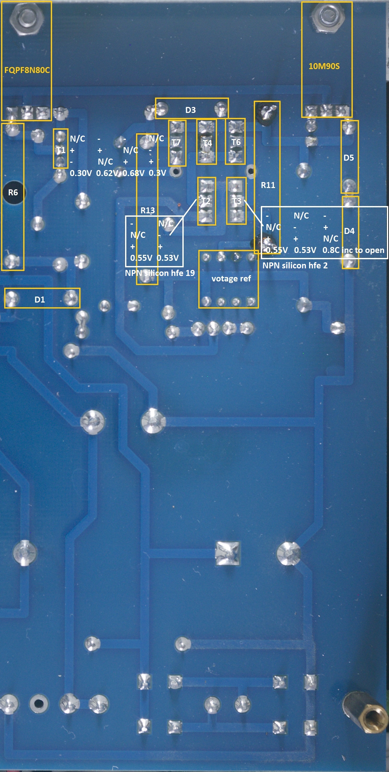
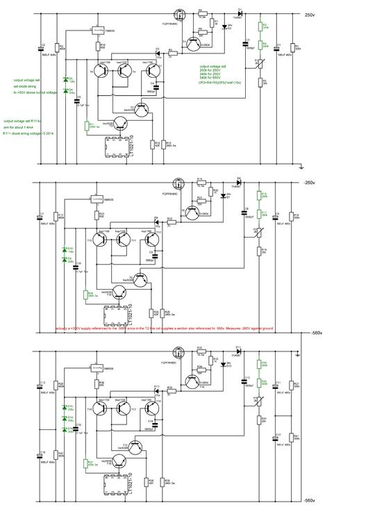
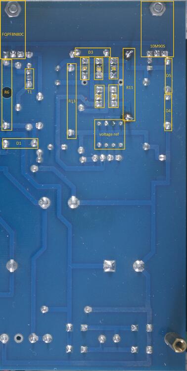
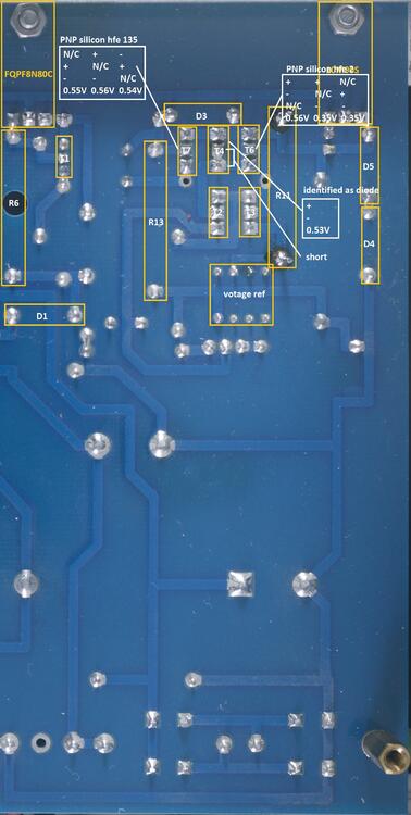
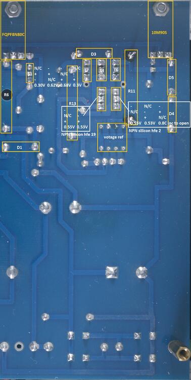
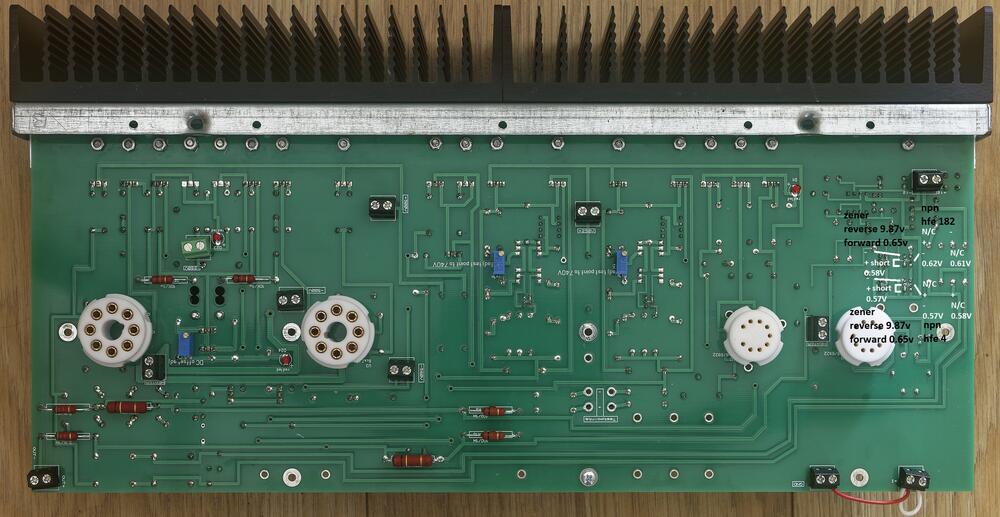
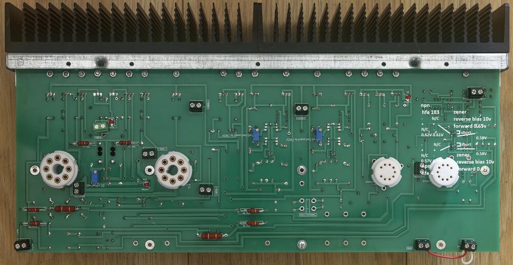
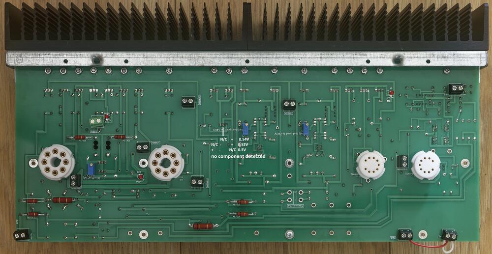
2 pointsSince the T2 needs a complex power supply I am also including a T2 power supply testing guide. There are multiple options for the T2 power supply but the one I built is: The gerbers can be found here: <insert link> The guide is intended for both pre-power on verification of an amp build, verification of voltages on power on and general troubleshooting. All tests are performed using a Brymen BM869s and peak DCA75. Using a different multimeter may effect the results slightly but you should still get similar behaviours and ball-park figures. All tests are performed with the psu not connected to an amp and no mains transformer connected. unfortunately many of the transistors are packed tightly together so it is not easy or really possible to get test probes onto all the legs of all the transistors from the top and so the verification guide will be separated into two halves: testing from the top and testing from the bottom. Since all the high voltage power supplies are basically identical except for differing values for some resistors ad the pre regulator zeners I will cover one psu rai and the diode tests and dca75 tests should be the same for the other high voltage rails. (The 500V and above rails also have two caps in series with bleed resistors in parallel for the input smoothing and output smoothing to reduce the financial cost of the caps and increase the cap options) The low voltage rails are trivial - diode bridge, bulk cap, monolithic off the shelf regulator and smoothing cap and so will not be covered. NOTE the 3w resistor which direct connects to the 10 volt reference will get hot (depending upon the supply rail) it can reach 80C+, If you look at my schematics above I suggest increasing the value of the resistor to reduce the current and decrease the temperature. Also raise it from the pcb as much as possible to keep it away from the nearby 0.1uF capacitor. NOTE if you use 0.1% precision resistors for the output voltage set resistors then they must be rated at above 250V for the 560V rail or (in my experience if you use 250V rated working voltage resistors their resistance will drift higher and higher with time and the 560V rail will eventually hit the zener string voltage of 600V and this will cause an uncorrectable dc offset in your T2 amp). Transistor and diode location Top The two ksc5026 (T3 and T2) form a long tail pair with T3 input being the 10V reference and T2 input being the the voltage across R5 (and half of P1) in the voltage set string. To improve the performance of the differential amp T6 and T4 form a current mirror. R12 is the common resistor for the long tail. The output of the long tail comes from the collector of T3 and goes to T7. Probe Tests from above Diode test of the zener pre regulator D5 and D4 measuring across each separately, you will get about 0.6V drop, probes reversed the multimeter will register a steadily increasing voltage until it shows open. This is true of each zener in the string. Diode test D2 you will get about 0.6v drop in one direction and an instant open in the other Diode test D1 you will get about 0.52v drop in one direction and an instant open in the other Diode test D3 you will get about 0.54v drop in one direction and an instant open in the other Note it is possible for a transistor to fail in such a way it has very little gain but still has a diode drop and so diode checking transistors is not a foolproof measure of a transistors health. But 0V drop when not expected indicates a short etc. Diode and dca75 tests of the 10m90s NOTE the 10m90s has a live tab and absolutely must be insulated from the heatsink it is mounted to. Like the 10m90s in the t2 amp boards the 10m90s measures the same when the polarity of the probes has been reversed. Just like the T2 amp the peak dca75 can't identify this component in circuit and variously shows it as a low voltage zener ~ 1.6V or an led. Diode and dca75 tests of the fqp8n80s The peak dca75 can't identify this component in circuit and variously misidentifies it as two diodes or a diode and led. Diode checks from underside Transistor and diode location Bottom Diode test T1 2N3904 NPN transistor. forms the active part of the current limit circuit. It monitors the current through R15 and when the voltage drop across the resistor gets too high T1 starts to cut off the pass mosfet FQPF8M80C. If you get correct voltage output with no load but any load massively decreases the output down to about 75V suspect T1 has gone short circuit. Diode and DCA 75 test T2 and T3 KSC5026 NPN transistor. These form the long tail pair differential amp which compares the voltage reference against a portion of the output voltage controlled by the trimmer P1 and the series resistor ladder R3, R4 R5. There should be very close to 10V across R5 if not one possibility is R3 and R4 have too higher a resistance value, possibility from using resistors with a too low working voltage - especially in the -560V rail which puts more than 250V across each of R3 and R4 in the series ladder. NOTE T2 is connected to a both ends of a cap and so this cap will slowly charge resulting in the diode test reading showing an increasing voltage drop until the multimeter finally displays open when the cap has charged to the same voltage as the meter outputs and so no current flows at all fooling the meter into thinking there is an open circuit. This does not occur with T3 The dca75 reliably and correctly identifies T2 as a NPN silicon transistor hfe 19 and T3 as a NPN silicon transistor hfe 2. Diode and DCA75 test T4, T6 T7. Ksa156 PNP transistor. T4 and T6 form the current mirror for the long pair differential amp. NOTE T4 has base and collector shorted together and so measures similarly to a single diode. The DCA correctly and reliably identifies T7 as a PNP transistor hfe 135 The DCA obviously identifies T4 as a diode junction if you don't connect the 3rd lead, otherwise it just reports a short between two of the leads - which is correct. The DCA correctly and reliably identifies T6 as a PNP transistor hfe 2 <<<work in progress>>>


 2 points
 -
Bumping this back to the front. The goal is $3k this year. Get me close and I'll cover the gap. If the total exceeds $3k and I'll donate a matching 10%. Make it hurt folks, I ain't skeerd.2 points
-
2 points
-
2 pointsI want to give more info to encourage listening, but will hold off. This is a big picture piece about how doctors treat patients pain, especially women, how patients lie to themselves if they already consider themselves "defective", how sympathetic one is to those causing pain and what it means if you're not sympathetic? Anyway... https://www.nytimes.com/2023/06/22/podcasts/serial-the-retrievals-yale-fertility-clinic.html https://www.vulture.com/2023/08/retrievals-serial-podcast-nyt-review.html https://podcasts.apple.com/us/podcast/the-retrievals/id1691599042?i=10006187324692 points
-
2 points
-
2 pointsThis will be a long drawn out post. Just a fair warning for those with better ways to spend 15 minutes or so. I hadn't posted about this here, but the last couple of months have been extremely difficult for my Mother. As it happens her husband stopped making the payments on the motor home (unbenounced to her) that they lived in. To make matters worse, it was close to being paid off. She had 3 days notice of repossession (they're both in their 80's). Couldn't find a way to stop that from here. But I was able to find a used 40' bumper pull trailer in great shape, very close to her. She was able to make that purchase, and the trailer was supposed to be delivered in 3 days time. So just a short hotel stay. That turned out to actually take over 3 weeks and a $2000 hotel stay. She's on a very fixed income. Then, after locking up her old motor home and actually cutting the water and electric hook ups, the bank decided that the motor home wasn't worth repossessing. The giant slide-out had rusted frozen after nearly 20 years in the South Texas beach weather. Also with my Mother and her husband both being legally blind, they had no idea that they were living in a roach infested, mold infested, horrible environment. They had a pretty bad roof leak. My Mom has COPD, and could barely walk from one end of the 32' motorhome, to the other. So, this frozen up motor home that wouldn't start, and was going to cost almost $4000 to be removed from the RV park they live in, the bank decided to abandon at the RV park, leaving my Mother on the hook for removal. Mind you, the bank held the title, left the motorhome locked and unusable (no hook ups). After talking to several businesses, my Mother discovered that no one would even consider moving it without a title. Long story longer, the bank wasn't able to get away with their despicable activities. I fully understand that the mortgage was behind some eight thousand dollars ( however, even though he had missed 8 payments, he had made 6 payments after that. Payments that the bank had accepted). And again, they were literally a few payments away from being payed off, minus the 8 back payments. She did end up having to make rent on two lots for one month, once the new trailer was finally delivered, and the old motor home was still in the old lot space. So, to catch up... They found a company to haul away the motor home with a giant wrecker. This company charged the bank (the legal owner) space rent, while they started refurbishing the motor home. The bank settled with them for lot rent and removal fees. The bank also settled with the RV park for lot space rent (2 months) which the park gave to my Mother. The RV sales company that turned a 3 day delivery into 3 weeks has agreed to reimburse my Mother for 80% of the hotel bill, and the hook ups that they were supposed to do and didn't, which my Mom had to pay someone else to do. Also the payment on the trailer was knocked down $130 a month. They told her that to qualify for the loan, she'd need an extended warranty. Turns out that was bullshit. And she had only financed $7000, and paid cash for the other $11,000. People really like to fuck over Senior citizens! Today I got the news that my Mother qualified for Medicaid. This also qualified her for a helper to come in 14 hrs. a week to clean, do laundry and all the shopping. My Mother and her husband can't drive anymore. He's almost fully blind, and she's loosing her sight pretty quickly ( both have macular degeneration). The Dr. has told her that her COPD is vastly improved (no mold or roach poop for a few months now). And finally, South Texas has no real transit help for Seniors or handicapped individuals. The bus they paid for to get to Dr. appointments is now also covered by Medicaid. That and they qualified for Meals on Wheels (more of a logistics challenge than a financial one). So, what was a complete pain in the ass, and absolutely despicable behavior by the bank (at least in my opinion), has now turned into a bit of a rainbow after a bad storm. I can't thank my Cousin enough, who spent hour after hour moving, boxing, cleaning and redelivering all of the roach infested clothing and belongings. Also pairing down a ton of crap that they just didn't need. Happy ending!2 points
-
Once again this year I'm prepping to ride a century in support of the Kelly Brush Foundation. Between Zwifting as required by the rainiest spring in history, the MTBs, and getting outside as much as possible this summer I'm piling on the miles in preparation this year and should in proper form before the event. Once again this year it'll be an in-person ride up in VT, with friends mostly coming from near-by so we should have a strong crew of 8 with some riding the 50 and most doing the full 100 miles. For me this is the 12th century that I've done in support of either Northeast Passage or Kelly Brush and I'm hoping the recent trend of good weather continues. So the mission remains the same, I'm trying to raise a bunch of money again this year with a goal of $3,000. As usual, all of the donations are tax deductible and maybe some legislation will get passed this year to make that more meaningful but really, I'm hoping the motivation isn't just to get a write off. So for those that are interested, here's the link to my personal fund raising page - Nate's Fundraising Page. Any donation large or small is very much appreciated. A bit about KBF - they are a non-profit organization dedicated to assisting individuals with spinal cord injuries in finding ways to get out and enjoy an active lifestyle. For me, this is a cause close to my heart. I love the outdoors and the freedom to explore it in a variety of ways and have worked with organizations like the KBF for the last twenty years to help others do the same. Last year's crew with Kelly at the starting line.
 1 point
 -
Thanks everyone, nearly a third of the way there!1 point
-
1 point
-
1 point
-
1 point
-
My Blackcat analog showed up...yay. I ran out of espresso and have been using Inteligentsia Summer Solstice Blend from my last order and it's made supper espresso drinks albeit a bit of work to dial in. HS
 1 point
 -
1 point
-
1 point
-
1 point
-
Cigarettes after Sex. A lot of it. (Dream pop with a slight tint of melancholy)1 point
-
The Lost Flowers of Alice Hart (Prime Video Original Series Soundtrack) Hania Rani 2023 https://album.link/i/1698589835 Example: I have been waiting for the new Rani album for like six months (they released like 2 tracks in April) and it is still not out for a month and a half! Anyway, I was happy to find they dropped a soundtrack on the 4th. I have not seen the show, so no comment there, but I like the soundtrack. I do wish a lot of the works were longer. You can tell that many were written for the scene vs. writting a long composition and then just using a part of it in a scene. But I will take some Hania over no Hania.
 1 point
 -
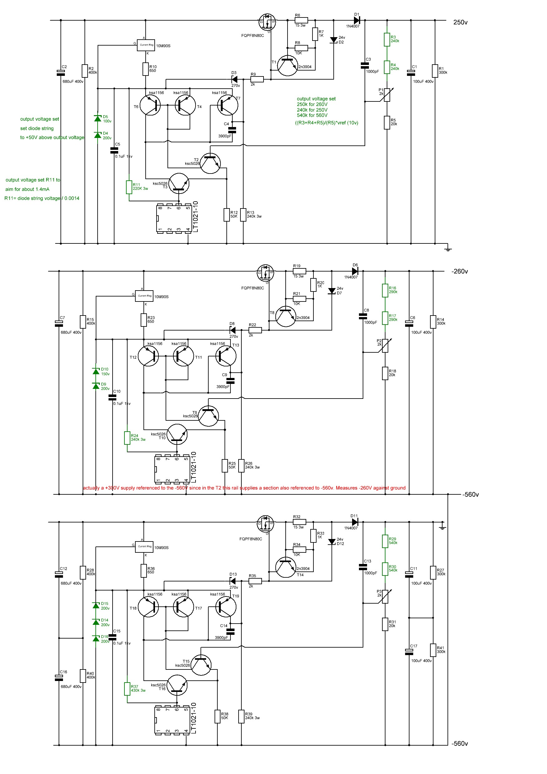
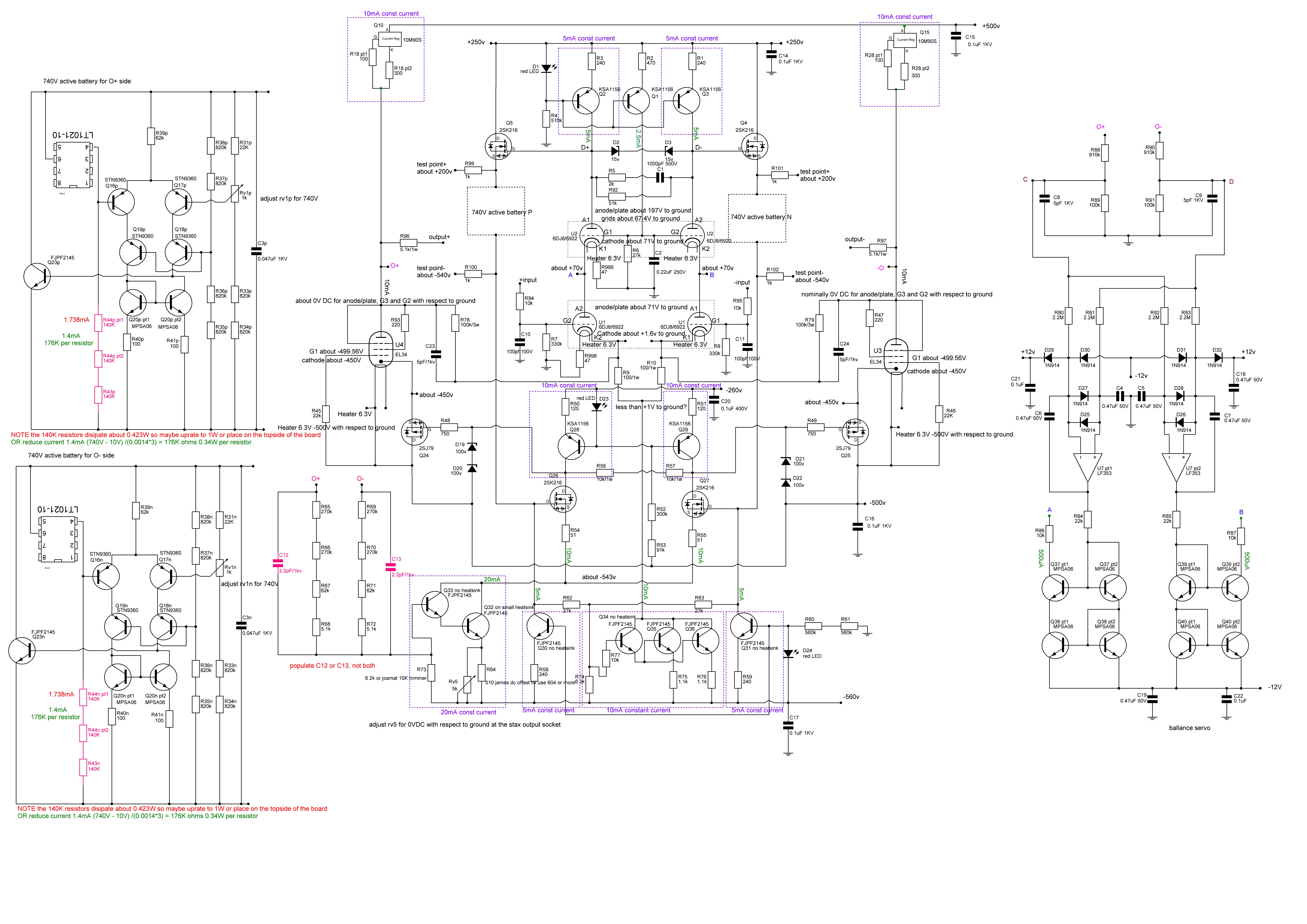
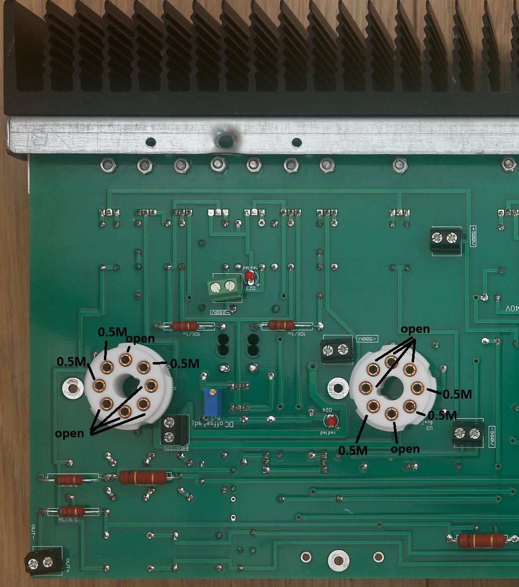
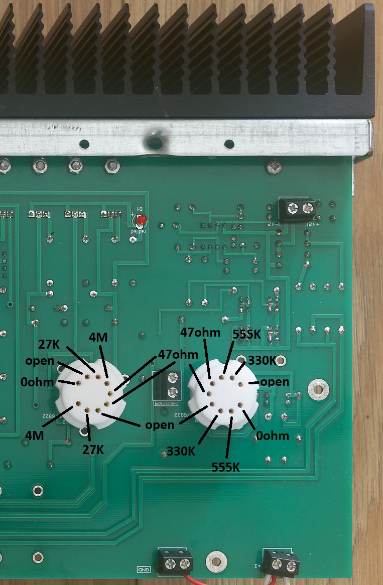
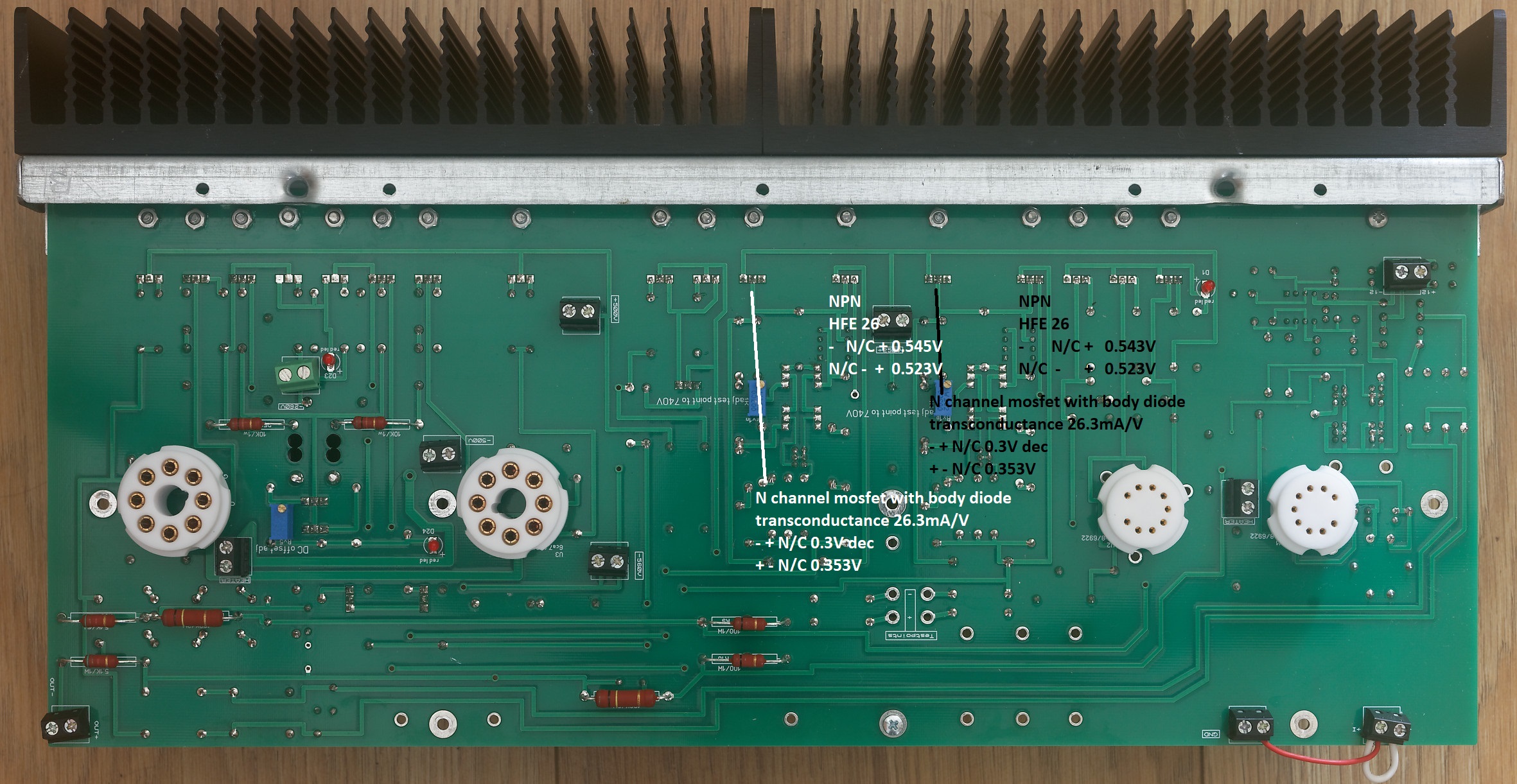
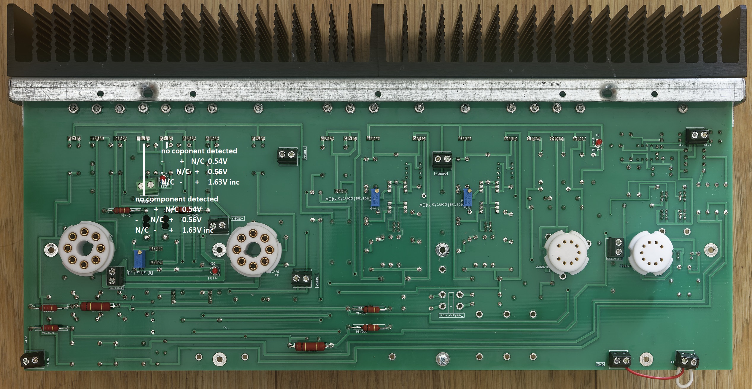
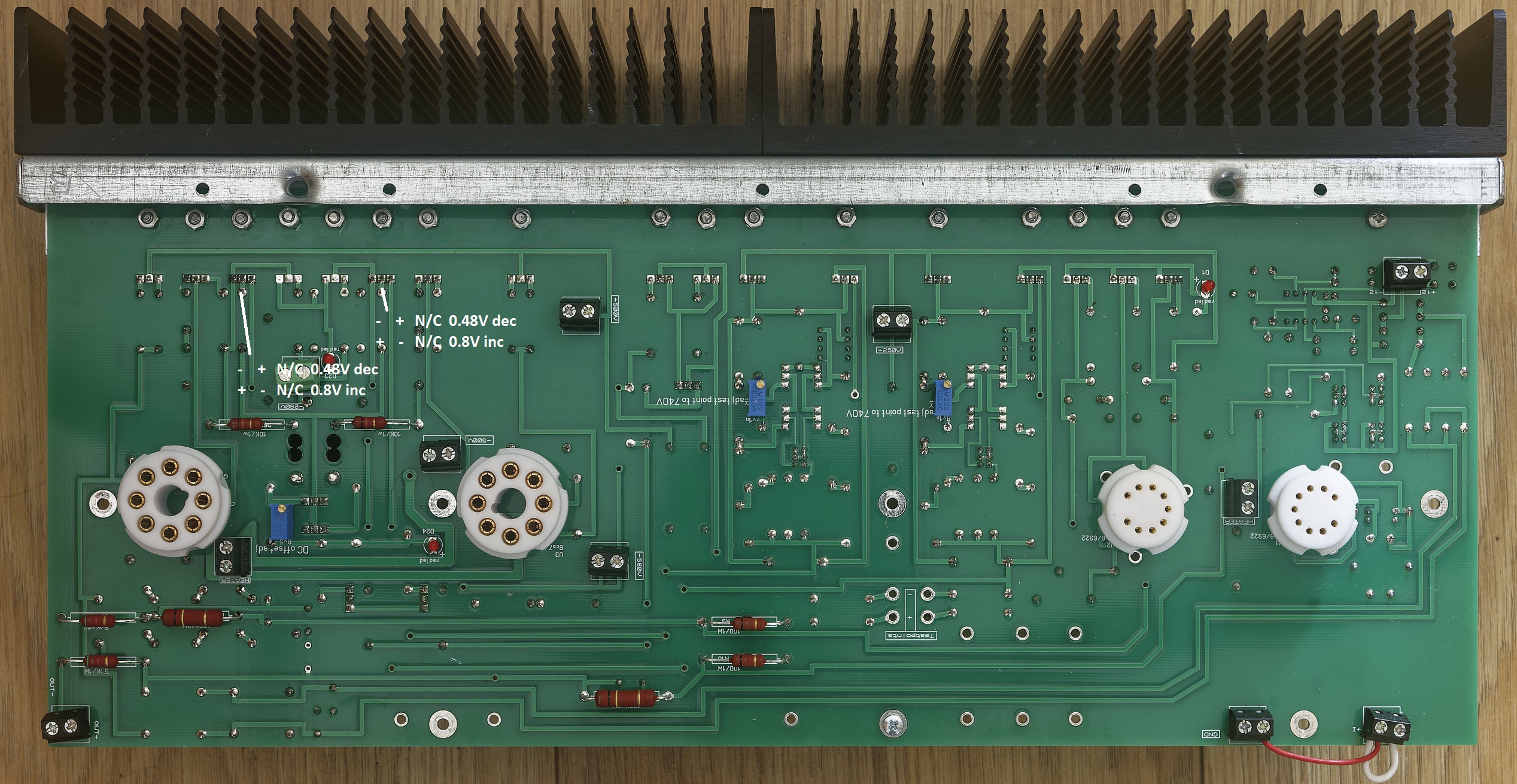
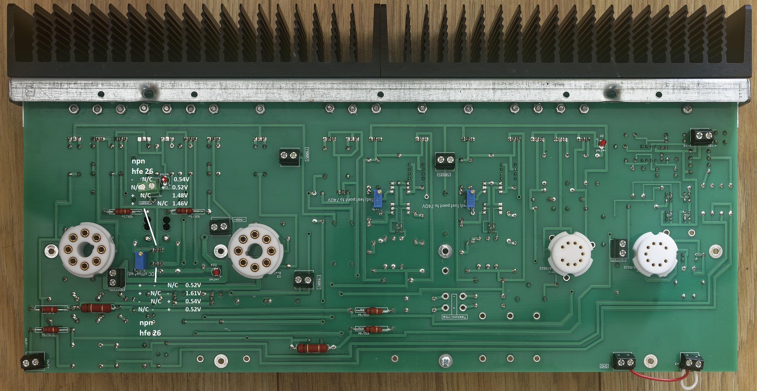
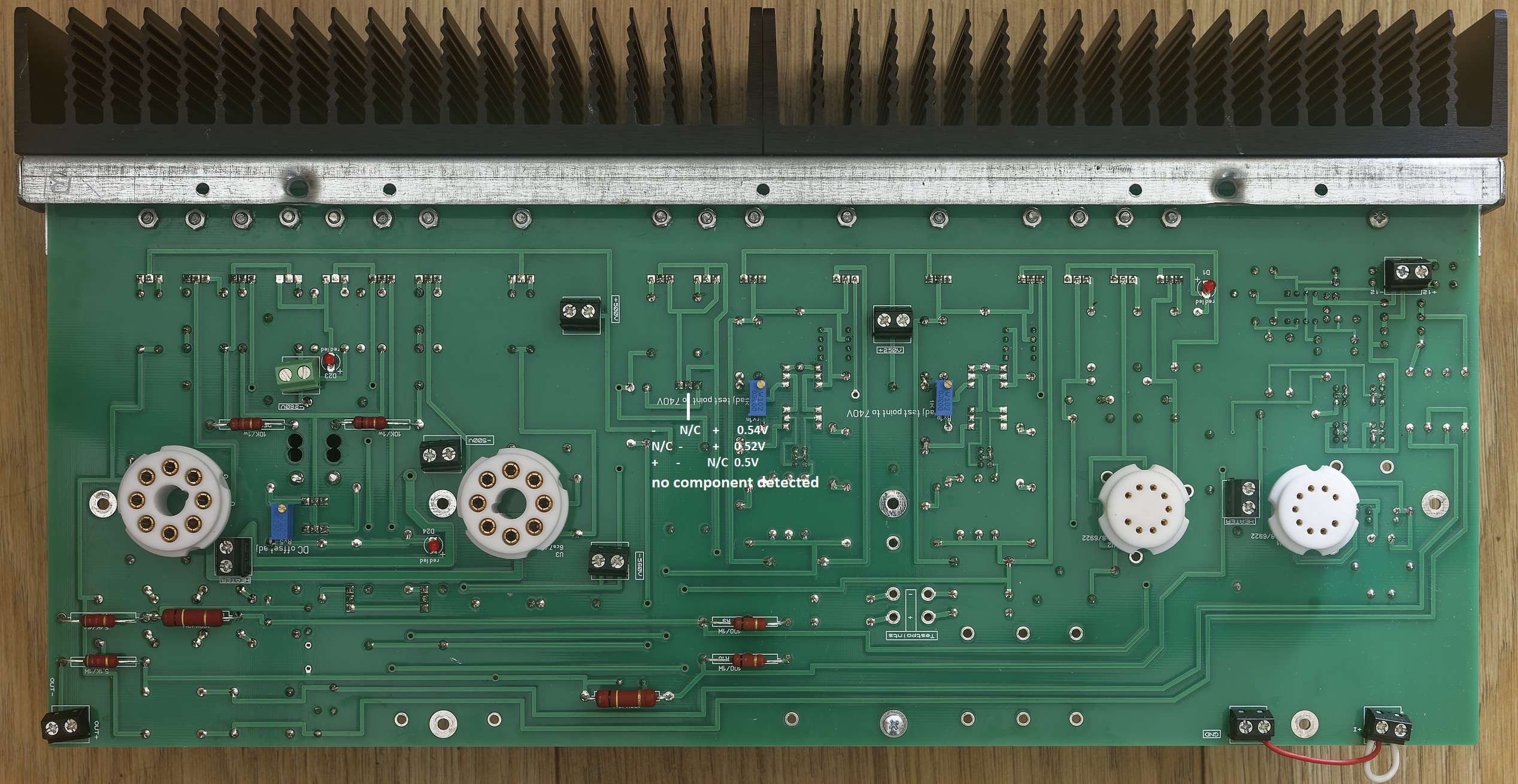
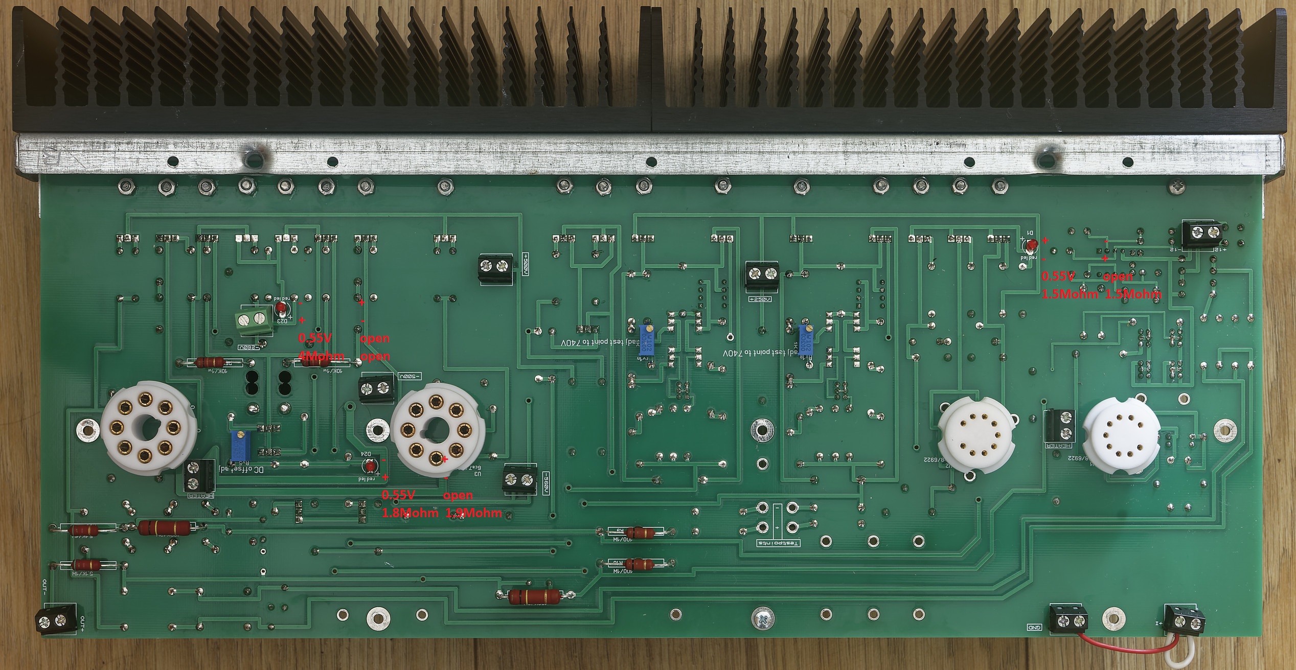
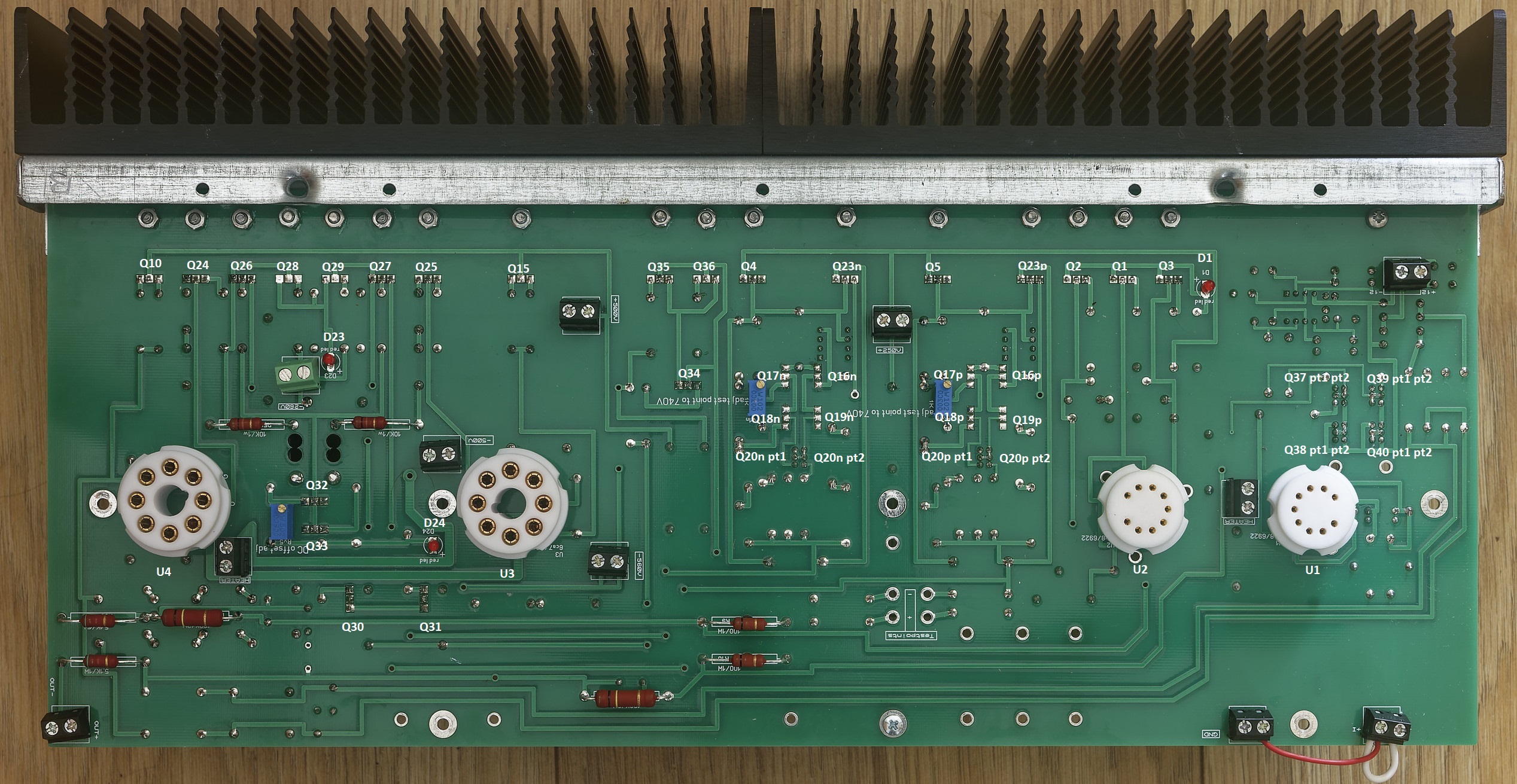
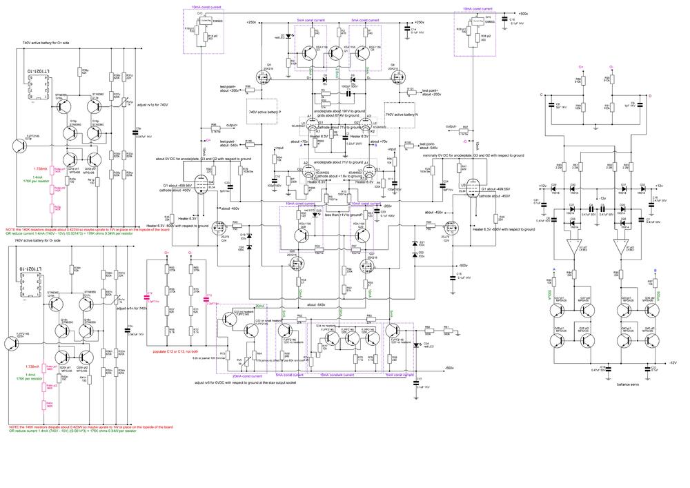
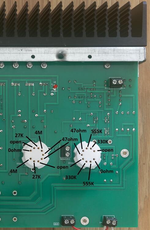
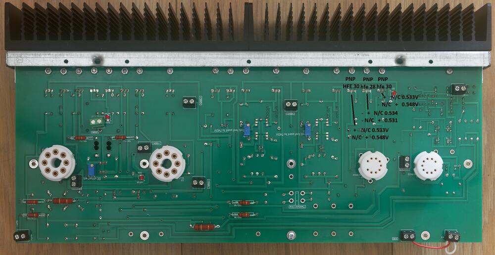
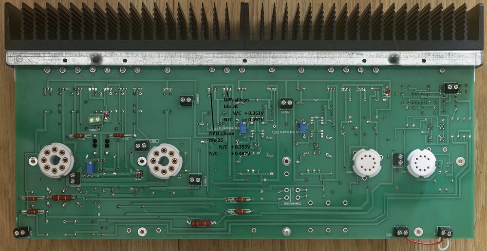
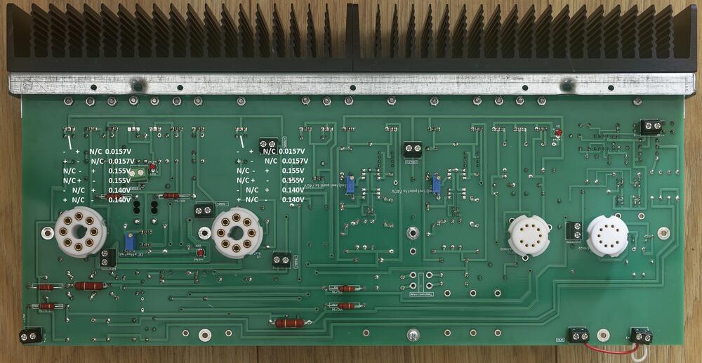
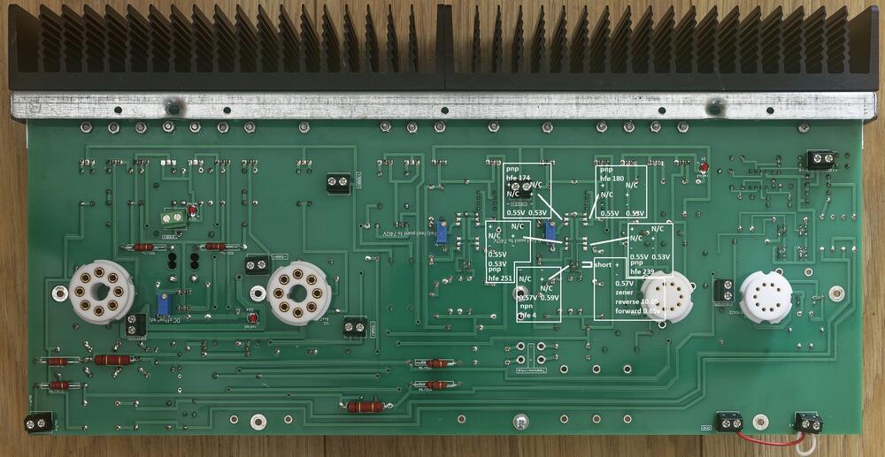
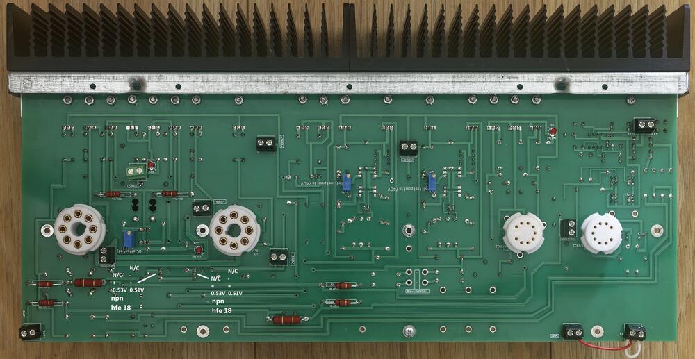
1 pointThe unofficial mostly modern T2 troubleshooting and verification guide. Weclome, this guide covers the mostly modern T2 which has the following schematic: The gerbers for the amp can be found here: https://drive.google.com/drive/folders/1r3g2TAtBUaBdiMorTWX7yYgeJ7maQbYW and the gerbers are staxt2nc3fdh7.zip The guide is intended for both pre-power on verification of an amp build, verification of voltages on power on and general troubleshooting. All tests are performed using a Brymen BM869s and peak DCA75. Using a different multimeter may effect the results slightly but you should still get similar behaviours and ball-park figures. Transistor and Diode Location Section 1. Build verification with no valves installed and no wires/volume control connected to the amp All of these checks can be performed with a multimeter from the top side of the amp board leds Checks. All 3 leds on each channel should read about 0.55V voltage drop in forward bias (multimeter + terminal/red lead connected to led + and multimeter - terminal black lead connected to led -) and open circuit in reverse bias (swap the probes around) when tested with a multimeter in diode check mode. The leds will not light from the diode test due t the current draw if the components around them. The exact forward voltage drop will depend upon the characteristics of the red led but anything significantly different here indicates a problem. 0 voltage drop in both directions indicates a short across the led or the components it connected to. check for solder bridges and failed short transistors. 0L indicates in both directions means the led has dry solder joints or is blown. using a multimeter in resistance mode check the leds D23 close to the -360VDC psu input. In forward bias expect around 4M ohms. With the probes reversed you should get open circuit. D24 is the led closest to the octal socket for the EL34 and should read about 1.8M in forward bias and about 1.9M in reverse. D1 is between in the 9 pin sockets but close to the heatsinks. This should read about 1.5M in both directions. Readings in both directions of a few hundred K ohms or lower indicate the led may have been leaky or a transistor it is connected to has gone short circuit or a solder bridge. Input terminal checks With the multimeter in resistance mode and the - terminal connected to the amp ground, and the positive terminal connected to the + input of the amp you should get about 340K and the same for the - input. Naturally expect the same results for the other channel. If significantly different suspect incorrect resistors for R94, R7 (positive input). Or R95, R8 on the - input. Output terminal checks With the multimeter in resistance mode and the - terminal connected to the amp ground, and the positive terminal connected to the + output of the amp you should get about 0.5M and the same for the - output. Naturally expect the same results for the other channel. Valve Socket Checks. With the multimeter in resistance mode and the - terminal connected to the amp ground, and the positive terminal expect the following resistances for both EL34s: (socket viewed from the top of the amp). (note the 0.5M reading may start lower and quickly ram up and the small capacitors in the circuit are charged by the multimeter). For the 6922s (socket viewed from the top of the amp) Diode Checks of transistors Note it is possible for a transistor to fail in such a way it has very little gain but still has a diode drop and so diode checking transistors is not a foolproof measure of a transistors health. But 0V drop when not expected indicates a short etc. Diode checks KSA1156 checks Q1, Q2, Q3 two of the ksa1156s (Q2 and A3) measure the same in diode mode the centre one (Q1) differs slightly. All combinations of probes and pins on a transistor result in open circuit unless otherwise shown otherwise: + indicates positive multimeter probe attached, - indicates negative multimeter probe attached n/c indicates no probe attachment. Note: for the other channel EACH KSA1156 is rotated 180 degrees about the y (vertical) axis. Peak DCA in circuit testing Q1-3 The peak DCA 75 identifies all 3 transistors as PNP silicon. The centre with a hfe or around 28 and the other two with slightly higher hfe of 30 to 31. This test is reliable, anything significantly different indicates a problem. Note it is easier to do these tests from the underside although you can hook up the dca proe hooks to something like a sensepeek weighted self standing spring loaded probe tip assembly and test easily from the top (https://sensepeek.com/pcbite-20 Diode check and Peak DCA 75 for Q23P FJPF2145 This is reliably identified as a NPN with hfe 26 and is part of the virtual battery connected to the + output side of the channel. NOTE: It has a mirror image pinout compared to the ksa1156s. Diode check and peak DCA 75 check for Q5 2SK216 This is reliably identified as a N channel mosfet with body diode and has a transconductance of 23.3mA/V. Although not part of the virtual battery it is directly connected to it. WANRING This transistor has a live mounting tab and must be fully insulated from the heatsink. A resistance check from the metal tab to the heatsink it is mounted on absolutely must read open circuit. Diode measurement for this transistor does not show a stable reading. In this case dec indicates a reading that decreases over time. The next two transistors in the heatsink row are Q23N and Q4 which perform exactly the same role and are exactly the same type of transistors as Q23P and Q5 respectively and should measure about the same I got 28mA/V for the Q4 so expect a little variance here). NOTE: on the other channel the order of the 2SK216 and FJPF2145 are reversed. Diode check and peak DCA 75 check for Q35 and Q36 FJPF2145 These are the current providers (driven by Q34) for a 10mA constant current source that feeds the input 6922s. The job is equally divided between them and they should measure the same. The DCA75 reliably identifies them as NPN silicon hfe 25-26 Diode check and peak DCA 75 check for Q15 and Q10 (10M90S) These are identified out of circuit by the dca75 as N channel depletion mosfets. However, in this circuit they provide anode current and are wired in such a way the DCA75 can not identify them and reports no component. The DCA75 should not report any shorts and the metal mounting tab is live and absolutely must be insulated from the heatsink they are mounted on. Q15 and Q10 are identically configured and should measure the same. The gate and cathodes are connected together with resistors totalling only 400ohms so the diode drop voltages will be lower than for the other transistors also unlike the other transistors all combination of probes will result in a voltage drop. The voltage drop should be the same in the forward and reverse directions. Diode check and peak DCA 75 check for Q28 and Q29 (KSA1156) These are identified out of circuit by the dca75 as PNP silicon. However in this circuit they are wired in such a way the DCA75 can not identify them and reports no component. Each should measure the same. Diode check and peak DCA 75 check for Q26 and Q27 (2SK216) These transistors do not produce stable diode voltage drops. Diode check and peak DCA 75 check for Q25 and Q24 (2SJ79) These transistors are not easy to get a stable reading on. Diode and peak dca75 Check Balance servo Q37 - Q40 (MPSA06) 4 of the MPSA06es have their collectors and bases shorted together and so can be considered to only have two pins as far as diode checking concerned. NOTE for any transistor with shorted pins only two dca75 probes were used (one to the shorted pins and the other to the non shorted pin) to avoid the dca just reporting probes shorted. Understandably ni this case the dca75 can not identify the component as a transistor and instead reports a 9.87V zener. All other transistors are correctly identified and hfe provided. Diode and peak dca75 Check Virtual Battery Q16 - Q18 (STN9360) and Q20 (MPSA06) the other virtual battery in the channel (just to the left) should measure similarly and is identically laid out. Q20 pt 1 has collector and base shorted. All 4 stn9360 should diode measure similarly. NOTE for any transistor with shorted pins only two dca75 probes were used (one to the shorted pins and the other to the non shorted pin) to avoid the dca just reporting probes shorted. Understandably ni this case the dca75 can not identify the component as a transistor and instead reports a 10V zener. All other transistors are correctly identified and hfe provided. The stn9360 are pnp and the remaining non shorted mpsa06 as npn Diode and peak dca75 check Q30 and Q31 (FJPF2145) Each transistor provides a separate 5mA current source and are directly connected to the virtual battery. With the led D24 across their base and emitter. Each is identically configured and should read the same. Dca75 reliably identifies both transistors as npn both hfe 18 Diode and peak dca75 check Q32 (on seperate small heatsink) and Q33 (FJPF2145) this forms a 20mA current source which is controlled by Rv5 and sets the DC offset. DCA75 reliably identifies both transistors as npn both with hfe 26 Diode and peak dca75 check Q34 (FJPF2145) Q34 provides control for Q35 and Q36 which creates a 10mA current source. The dca75 says no component detected. <<< IN PROGRESS >>> #include <usual_disclaimer.h> #include <usual_high voltage_warnings.h>


 1 point
 -
Oh dear. Today has been one of bad discoveries. First off, the 5D IV is running ancient firmware. After much banging of head against various objects, I managed to go from 1.17 to 1.4. I still cannot get the (gosh darn) Canon EOS utility for MacOS to connect to the 5D via USB. I was able to connect the 5D to my WiFi network and get things working that way. While all of the above has been stressful and headache inducing, it pales in comparison to this afternoon's discovery. Since yesterday I have tried every single one of my many CF cards with the 5D. It has rejected all of them. At first I wasn't too surprised as my CF cards are old and older. My cranky old 30D doesn't like most of them. My ID 5D classic is less picky. I now know why the 5D IV doesn't like any of them: It has a bent bin. The paste eating absolute chucklefuck previous owner shoved a card in the wrong way and either never noticed or never told anyone. I'm now weighing my options about whether or not I want to keep this camera. I still have not successfully gotten app that will report the camera's shutter actuation count. It's looking like I'm going to have to pursue that on (shudder) Windows.0 points