

Leaderboard
-
Hopstretch
High Rollers10Points16779Posts -
VPI
High Rollers5Points9103Posts -
dsavitsk
High Rollers4Points4955Posts -
TMoney
High Rollers4Points4682Posts


Popular Content
Showing content with the highest reputation on 10/07/17 in all areas
-
4 pointsHuevos Jeffero with last nights over the top hot (4 Habaneros, 6 cayenne, 6 Jalapeños from the garden) chili. Sent from my iPhone using Tapatalk4 points
-
Test Tone @ Home live right now: http://mixlr.com/illuminator/chat2 points
-
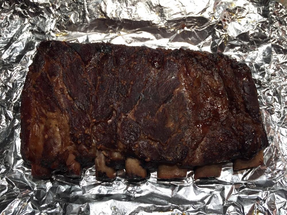
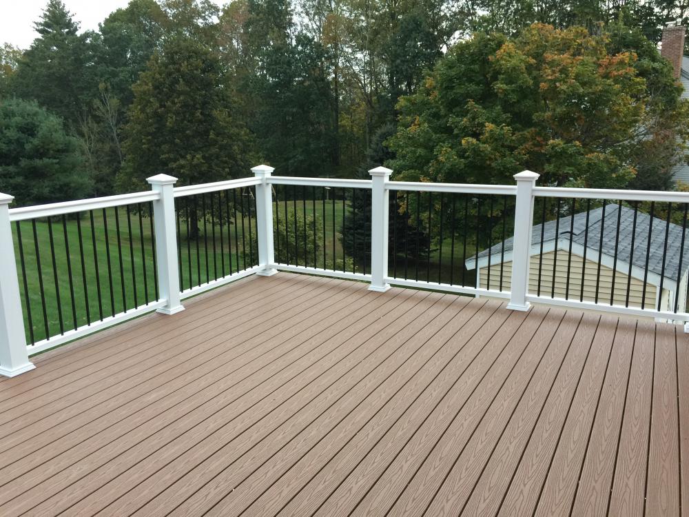
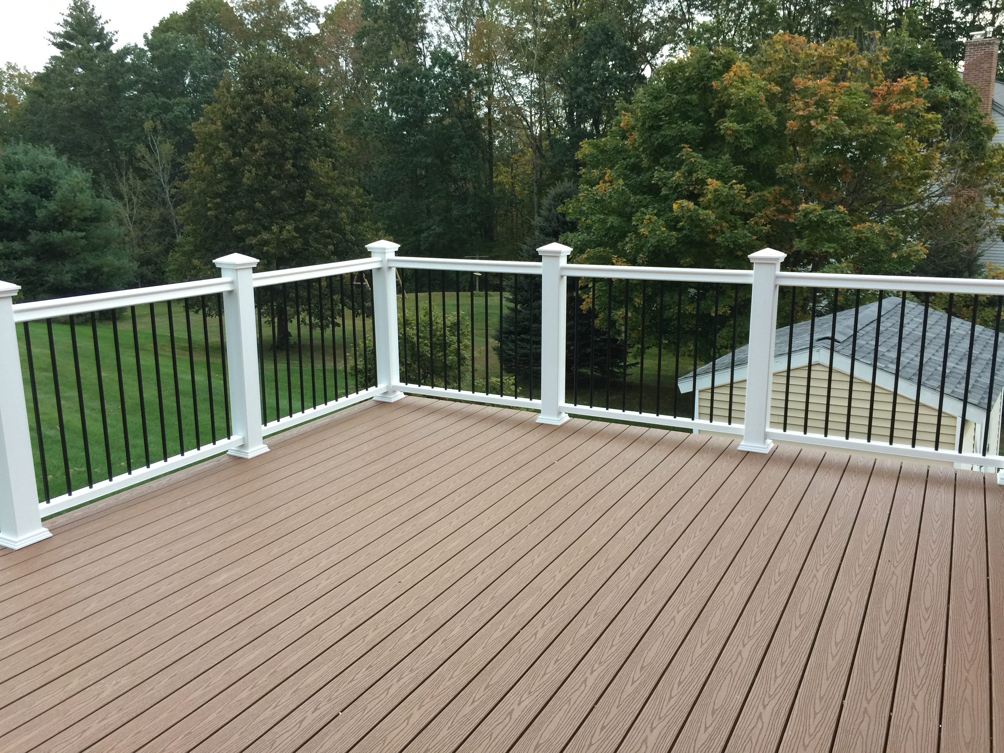
1 pointFired up the smoker today while working on the deck. The ribs came out great (there were 4 sets like this is total) and the deck isn't looking too shabby. Still have the other half of the railing to do but now that we've got it figure out it should go pretty quickly.
 1 point
 -
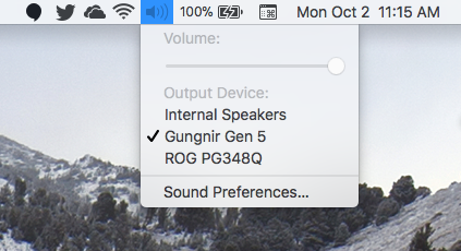
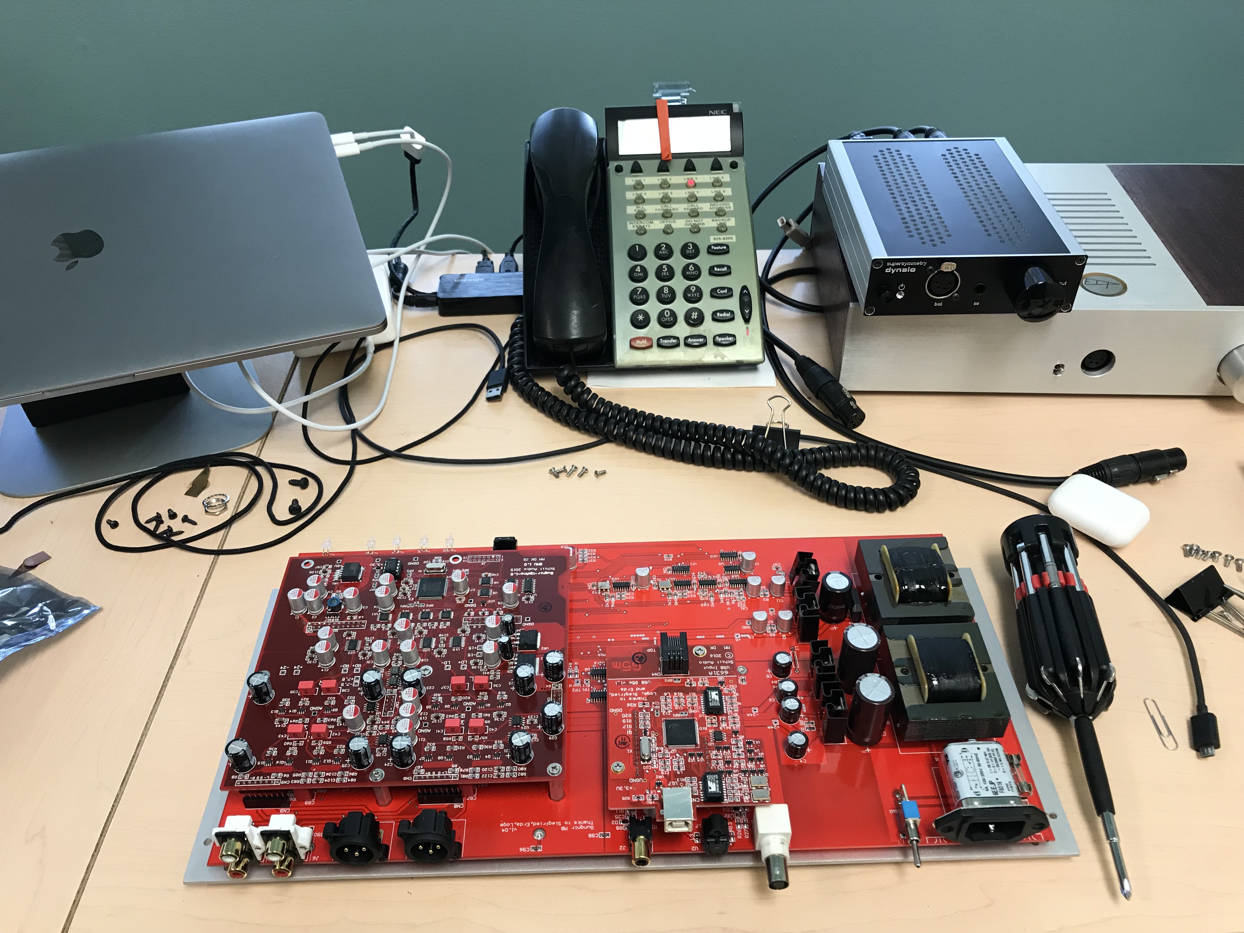
1 point1 point1 point1 point1 pointJust buy a custom gaming PC and 34" widescreen 100hz G-SYNC monitor like Jeff. Sent from my ONEPLUS A3000 using Tapatalk1 point1 pointI have installed Gen5 a few days ago. From the box it is sounds worse than my Audiobyte Hydra Converter + AES cable. There's no miracle happend!1 point1 point1 pointVery pretty Jeff. That is a beautiful thing that Brent will never have.1 point1 point1 point1 point1 point1 pointI have to say, the Silca Ultimate Hiro Edition is about the most serious piece of cycling kit I have come across. This thing is overbuilt to the extreme and the packaging that it came in puts several $10k+ pieces of Audio gear packaging to shame. To top it off they do not just send a cheesy little Allen wrench to put it together but instead send one of their overpriced but awesome wrenches. I am reluctant to put this thing in the garage. Sent from my iPhone using Tapatalk1 point1 pointNo pictures, but looking for something we'd never had, we went out for Nigerian food last weekend. It was very good.1 point1 pointHave no fear, garlic is well represented tonight — in the pesto and the beans.1 point1 pointDid the gen 5 upgrade to my Gumby this morning. It took about 30 minutes, start-to-finish. I'll leave it to others to describe any change in sonics, but I figure it can't hurt the eventual re-sale value. EDIT: If anyone wants the prior gen USB board to play around with, PM me and its yours for the price of shipping.
 1 point1 pointAlways appreciate that you don’t just tell me to Google it myself! Owe you a diet soda ...1 point1 pointThis is my wife's cogitation station. Supposedly it's a real one, but not sure how you would tell either way.
 1 pointtry this, there should be over 300 files, had to remove a couple of confidential ones see updated links on page 51 point1 pointI have received requests to share my adjustment procedures so I thought I would post it here in case others are interested. These steps are based on combination of compiling the excellent information JimL has posted and my own experience. All the trim pots except the 5K ones are for adjusting current setting of the current sources and sinks. And since they all use DN2540 which has quite a variance among samples, these setting will vary but the pre-set values in step 1 should provide a good starting point. You'll then need to fine-tune them a bit. Here are the adjustment/fine-tuning steps of the SRX Plus in sequential order: 1. Initial setup before first power on: (assuming 7mA of output current per triode of the 6SN7GTA/B) Output current source (the 4 100 ohm trim pots close to the large heatsinks): adjust the trim pots to 55 ohm if you are using 180 ohm in-series fixed resistor (250 ohm on silkscreen). These trim pots set the output current of the 6SN7GTA/B Output current sink (the 2 20 ohm trim pots between the upper 12AT7 tubes): adjust the trim pots to 12.5 ohm if you are using 75 ohm in-series fixed resistor (102 ohm on silkscreen). These trim pots set the current sink of the 6SN7GTA/B. Input current sink (the 2 500 ohm trim pots): adjust the trim pots to 410 ohm if you are using 1.2K ohm in-series fixed resistor (1.4K ohm on silkscreen) . These trim pots set the plate voltage of the upper 12AT7 (the ones closer to the 6SN7GTA/B). Adjust the 2 5K trim pots to be in the mid-point. These trim pots are used to balance the voltage of the plates of each of the two triodes of the upper 12AT7 so they are equal. The 5K pot and the 500 ohm pot will interact with each other a bit. 2. Insert all the tubes and power up the amp. If you have a variac, I recommend that you use the variac to gradually bring up the voltage for the first time especially if you are using NOS tubes that have not been powered on for a long time. 3. Check to see if all voltage (filament supplies, B+/B-, and the -20VDC) are all as expected and all the tubes lit up as expected. If everything appears normal, let the amp warm up for about 10 minutes before carry on to next steps. 4. The goal of this step is to set the output current of the 6SN7GTA/B to the desired value (7mA). Measure the voltage drop of the 100 ohm resistors of the output CCS (the 4 resistors between the large heatsinks and the .1uf/400V caps by the edge of the PCB). They should measure about 0.7VDC (0.7VDC/100R = 7mA). Adjust the 100 ohm trim pots to get the 0.7VDC voltage drop on these 100 ohm resistors. 5. The goal of this step is to set the output current sink to 17mA, 3mA higher than the output current. Measure the voltage drop of the 100 ohm resistors of the current sink (the 2 resistors between the 20 ohm trim pots and the single .1uf/400V cap between the two lower 12AT7 tubes). They should measure about 1.7VDC (1.7VDC/100R = 17mA). Adjust the 20 ohm trim pots to get the 1.7VDC voltage drop on the 100 ohm resistors. 6. The goal of this step is to set the two plates of each of the upper 12AT7 to be equal and about mid-way between B+ and ground. So if you are using B+ of 360VDC, the mid way is 180VDC. First attach the DMM probes to each of the two .22uf/1000V coupling caps where they are connected to the plates of the upper 12AT7 and measure the DC voltage between them. (in my case. I purposely left the leads of the coupling caps sticking out a bit so I can clip the DMM probes on them. With the 5K trim pot set at its mid-point, the measured DC voltage between the two plates tells you how well matched are the two triodes of the 12AT7 tubes used. If they are well matched it should be within 5 VDC or so. If it's more than 20VDC you may have problem**.) Adjust the 5K trim pot so the measured voltage is close to 0VDC. Next, move one of the DMM probes and clip it to the power ground (leave one probe still connected to one of the coupling caps) and adjust the 500 ohm trim pot so the measure voltage is about 180VDC (half of the B+). The adjustment of the 500 ohm and the 5K trim pots will interact with each other so you'll need to go back and forth a bit. 7. Let the amp warm up for another 15 - 20 minutes for the tubes to reach their stable operating state then repeat the adjustments again. Measure the balance via the headphone jack like you do with other Stax amps. If the two triodes in each of the 6SN7GTA/B are well matched you should see around 1 or 2 VDC or so. And this is perfectly fine. 8. Measure the offset via the headphone jack like you do with other Stax amps. Adjust the 20 ohm trim pot (output current sink) to bring the offset as close to 0 VDC as possible. 9. Assuming all adjustments are carried out without problem, you are done and ready to listen to music now ? This is an all tube amp without servo so the offset and balance etc. will never be spot on and will vary and drift a bit every time you power on the amp. That’s to be expected. 10. There is an optional step which I have not done myself - you can adjust the 2 100 ohm output CCS trim pots to bring the balance of each channel to 0 VDC. I have not felt the need to do it (maybe I got lucky with the tubes I have). If you choose to do so, try to adjust both trim pots in a converging fashion instead of adjusting only one of the two pots. You'll also need to "coordinate" this with adjusting the 20 ohm pot in step 8. Hope this helps. JimL and others please chime in and correct me. ** In my experience, with the 5K trim pot centered, if the voltage difference between the two plates of the 12AT7 is greater than 15VDC or so, you should still be able to adjust it to 0 VDC but you may encounter problem with buzzing noise. You can move the 12AT7 tubes around to minimize this voltage difference. In my experience, it's more important to have the lower 12AT7 (the one closer to the 5K trim pot) well matched to bring this voltage difference down.1 point


Important Information
By using this site, you agree to our Terms of Use.
Account
Navigation
Search
Configure browser push notifications
Chrome (Android)
- Tap the lock icon next to the address bar.
- Tap Permissions → Notifications.
- Adjust your preference.
Chrome (Desktop)
- Click the padlock icon in the address bar.
- Select Site settings.
- Find Notifications and adjust your preference.
Safari (iOS 16.4+)
- Ensure the site is installed via Add to Home Screen.
- Open Settings App → Notifications.
- Find your app name and adjust your preference.
Safari (macOS)
- Go to Safari → Preferences.
- Click the Websites tab.
- Select Notifications in the sidebar.
- Find this website and adjust your preference.
Edge (Android)
- Tap the lock icon next to the address bar.
- Tap Permissions.
- Find Notifications and adjust your preference.
Edge (Desktop)
- Click the padlock icon in the address bar.
- Click Permissions for this site.
- Find Notifications and adjust your preference.
Firefox (Android)
- Go to Settings → Site permissions.
- Tap Notifications.
- Find this site in the list and adjust your preference.
Firefox (Desktop)
- Open Firefox Settings.
- Search for Notifications.
- Find this site in the list and adjust your preference.