

Leaderboard


Popular Content
Showing content with the highest reputation on 03/13/20 in all areas
-
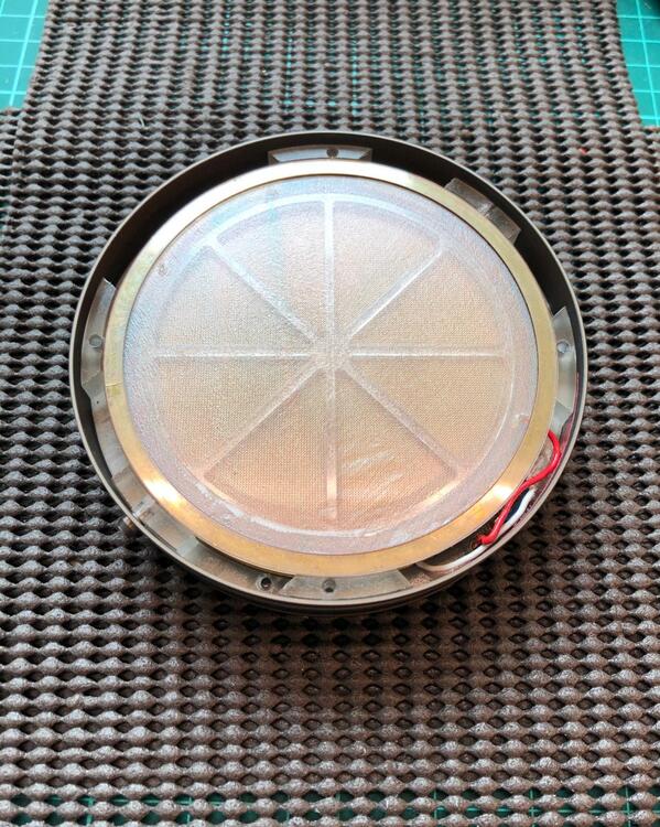
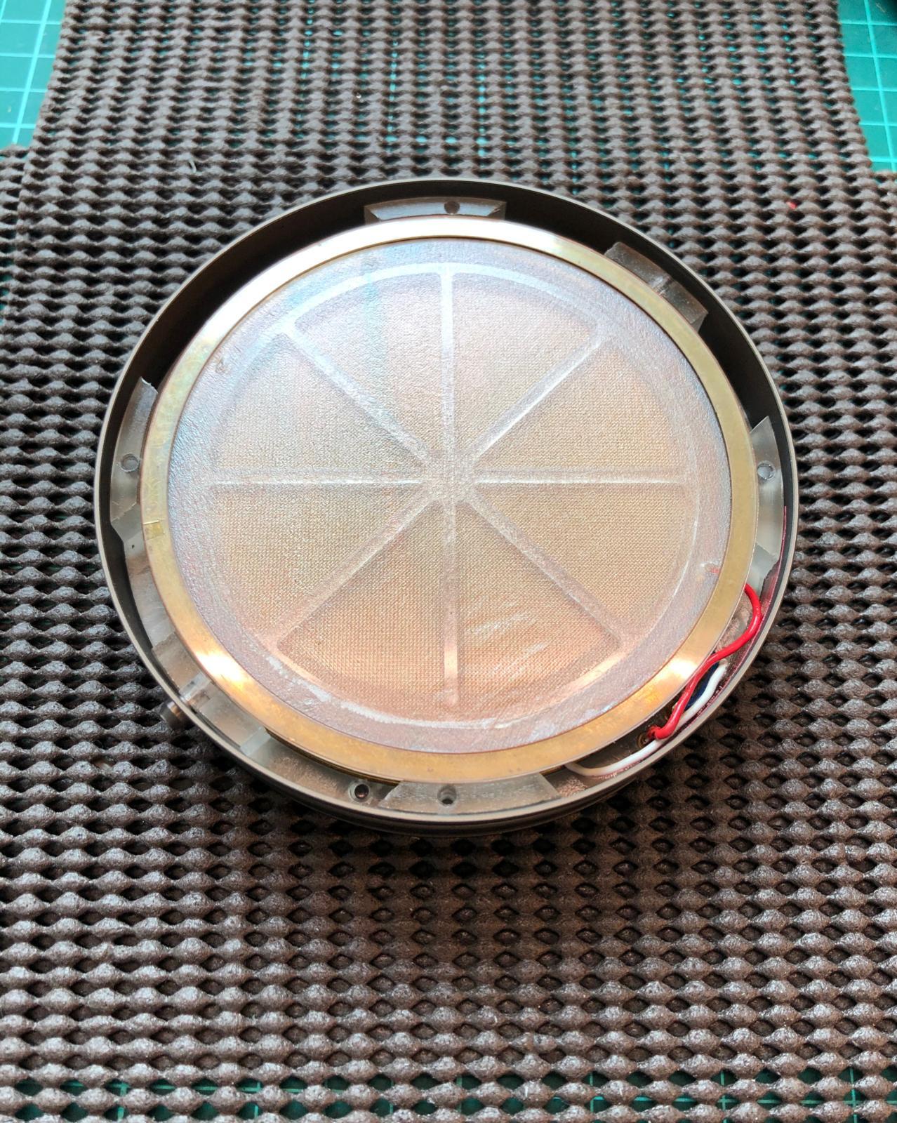
4 points4 points4 points4 points3 pointsAn omega arrived for imbalance repair. Pretty messed up inside with bias wire directly soldered on brass ring, faultly installed panel and worst of all a shadow seen at the part of the rim of the diaphragm , shown as a lunar shape at the bottom of the driver in the photo. Probably indicating a tear along the rim of the diaphragm. Treasure your omega(s) when they are still working ......
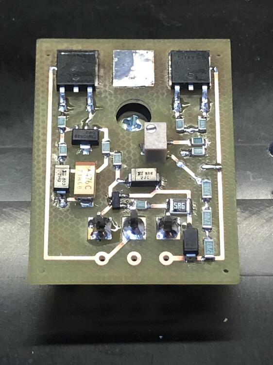
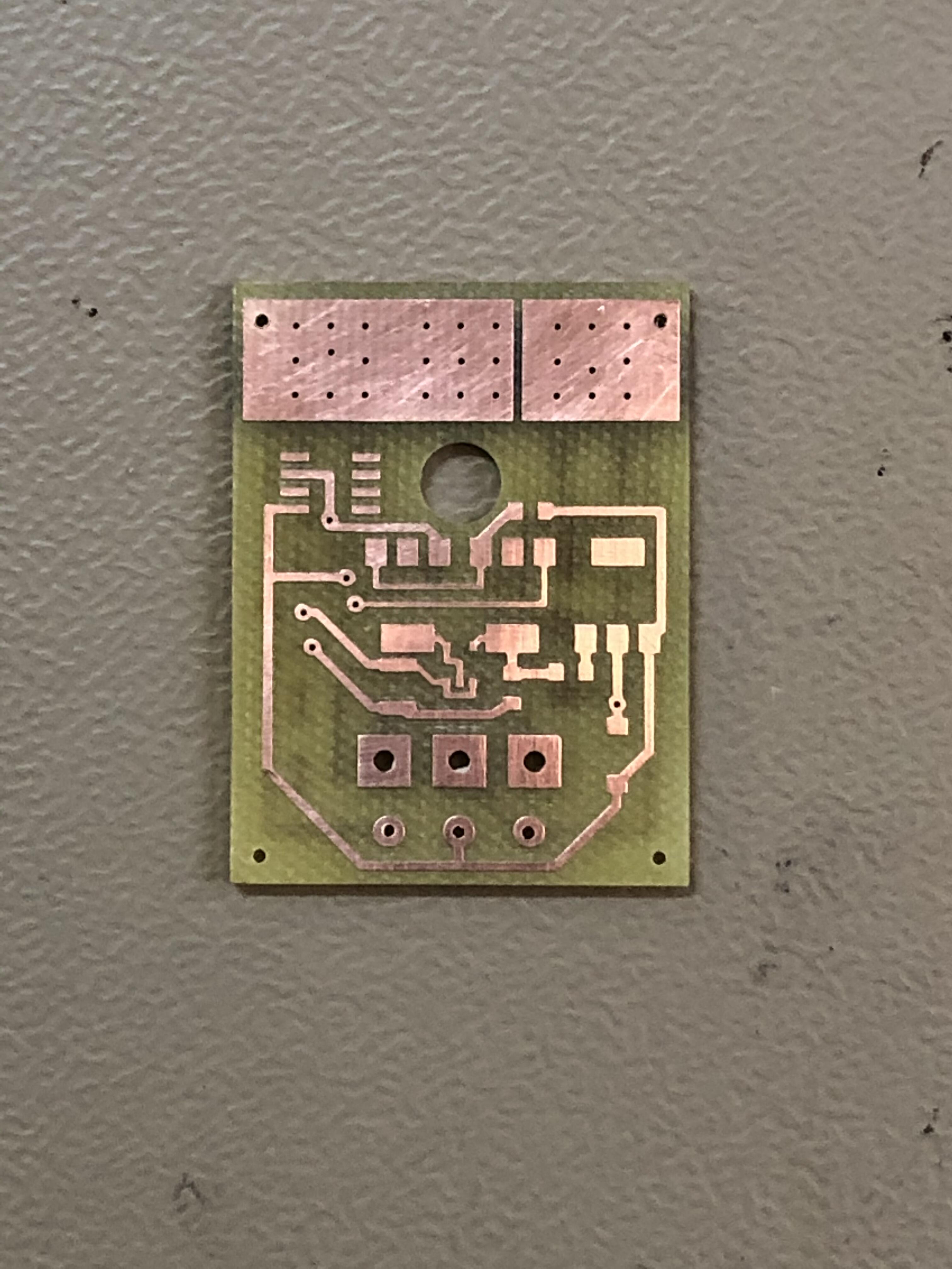
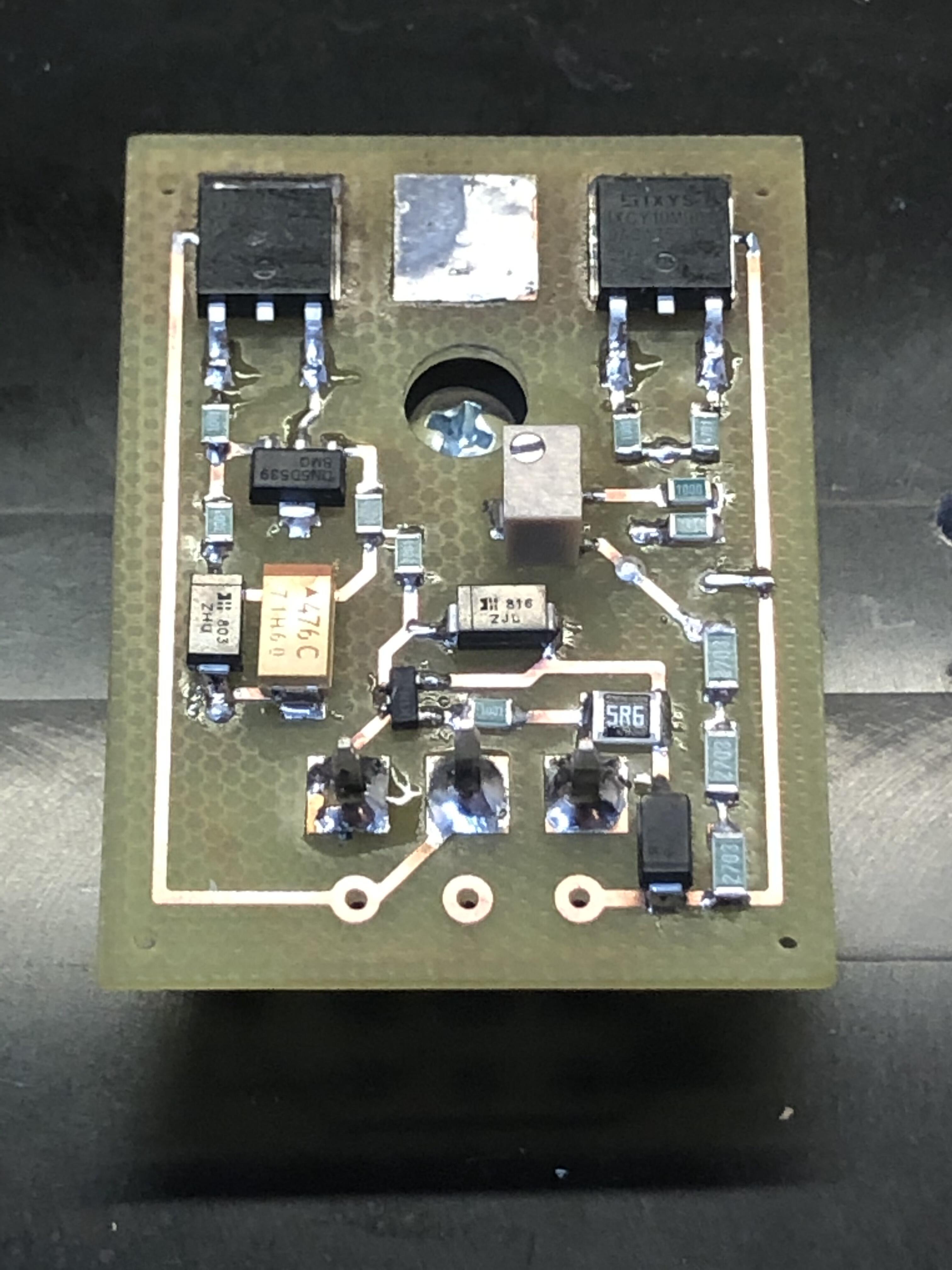
 3 points2 pointsToday’s exercise. Milled a double sided board and populated it. Now I know it’s fairly easy to solder this by hand. If you can solder a mini T2 board the GRHVxxx boards shouldn’t be much of a problem. Besides it’s funny. This board is essential the same as Kerry’s except no enable and a trimmer to adjust output voltage. Thanks for those mini boards Kerry.
 2 points2 pointsI haven't felt this bad about posting something in here since those GIFs of Nancy Grace dancing "sexily."2 points2 pointsYesterday I managed to escape from work for the day and go enjoy the outdoors with some coworkers.
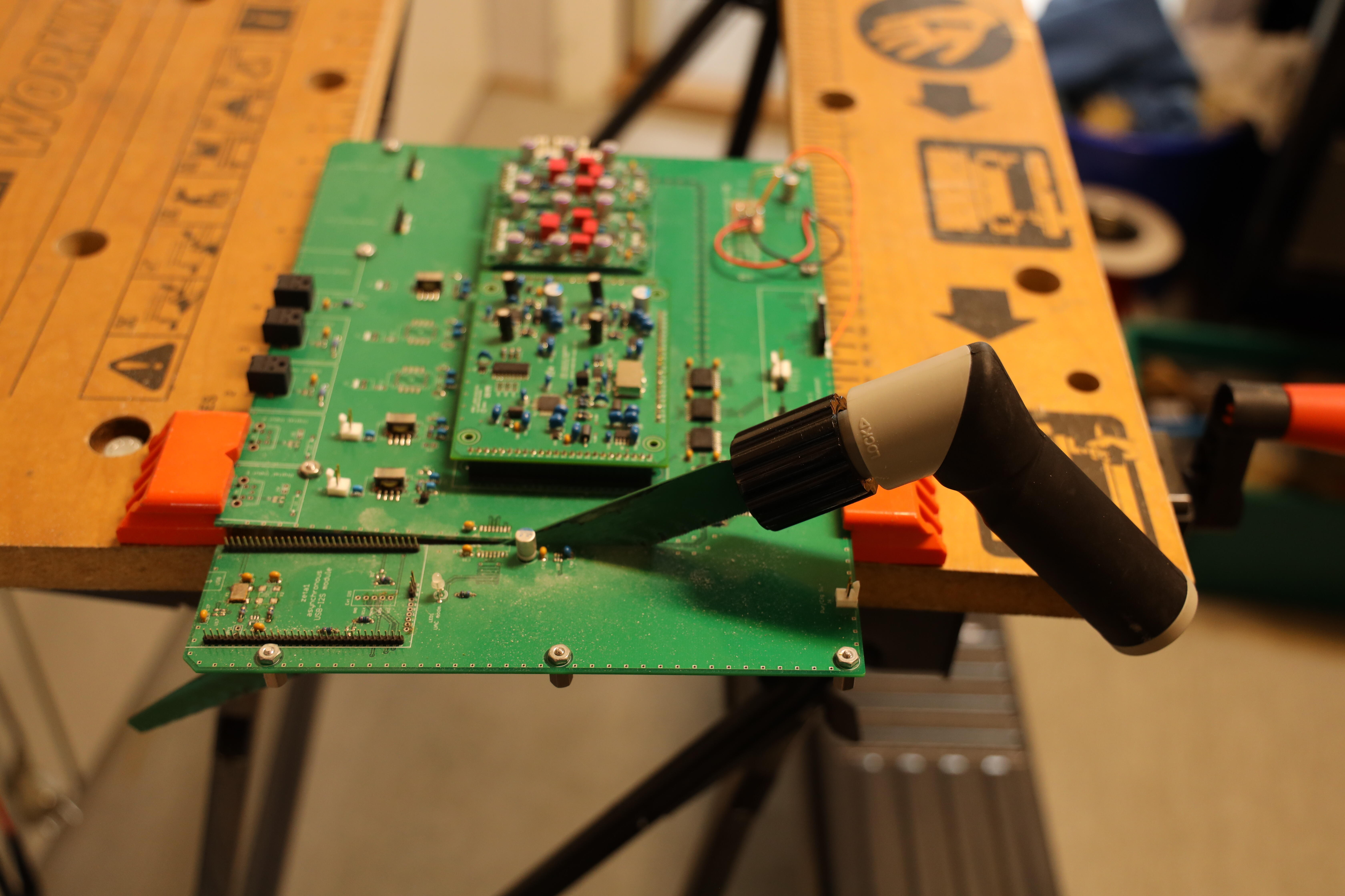
 2 points1 pointA dust free environment means a confined space with dust-free air sipply from HEPA Units filtering particles down to um-level and a positive air pressure to make sure that airflow is one-way-out only. It could be as small as a brench or as big as a factory. A normal working space along with a air purifier sitting at the corner or thorough cleaning is definately not a dust free enviroment, far from it. But in reality, there are some people who open their e stat driver, put it back and nothing happen. So whether dust gets into the driver or not is simply by chance. But if you do not want to throw the dice everytime , a dust free environment is definately needed. Some headphone makers revise e-stat designs from the typical stax type to make it less prone to dust contaminations so a dust free enviroment might not be necessary, but not for stax drivers.1 pointTable updated! BOM for boards will be posted soon in the first post of this thread.1 point^^ literally the first 'concert' I ever attended -- back in my Dukes of Hazzard days..1 point1 pointHere is a PCB with unnecessary area. A big metal saw and it’s fixed in a couple of minutes.
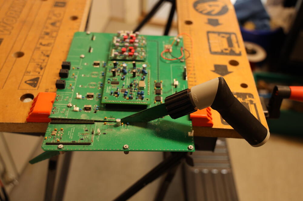 1 point1 pointI’ve got questions about using +/-450V supplies with mini T2. It would probably work alright, I can’t see why it wouldn’t. If using a drop down resistor for +220V there is a Vishay 24.9k/3W that probably will do (haven’t tested it - maybe I should or someone else). One other request is the location of stand of holes. Attached are templates for left and right boards - imperial and metric. I had to print them 100.4% to get scale 1:1. They don’t look nice but that is what I managed to do in Proteus. holes mini T2 Right v.23.PDF holes mini T2 Left v.23.PDF mm holes mini T2 Right v.23.PDF mm holes mini T2 Left v.23.PDF1 point1 point1 pointMight as well enjoy the finer things before they end up shutting down all restaurants due to this Corona crap.
 1 point1 pointHairstyle pop La Dernière Valse – Mireille Mathieu MONDO GROSSO: ラビリンス (Labyrinth, ft. Hikari Mitsushima)1 point1 pointFit February starts tomorrow, which means today is Fat Fuck Friday!
 1 point1 pointI've tested the DALE ones that KG specified in the BOM on my RF bridge, and they are exceptionally good, measuring 80k even at 200MHz with an effective parallel capacitance (actually of course a series inductance) of 0.2pF. That is bewilderingly good performance for a 3W power resistor. The Mills ones are wire wound IIRC, but non-inductive?1 point


Important Information
By using this site, you agree to our Terms of Use.