

Leaderboard
-
Augsburger
High Rollers14Points13165Posts -
n_maher
Administrators9Points27455Posts -
swt61
High Rollers7Points22241Posts -
VPI
High Rollers6Points9103Posts


Popular Content
Showing content with the highest reputation on 02/06/23 in all areas
-
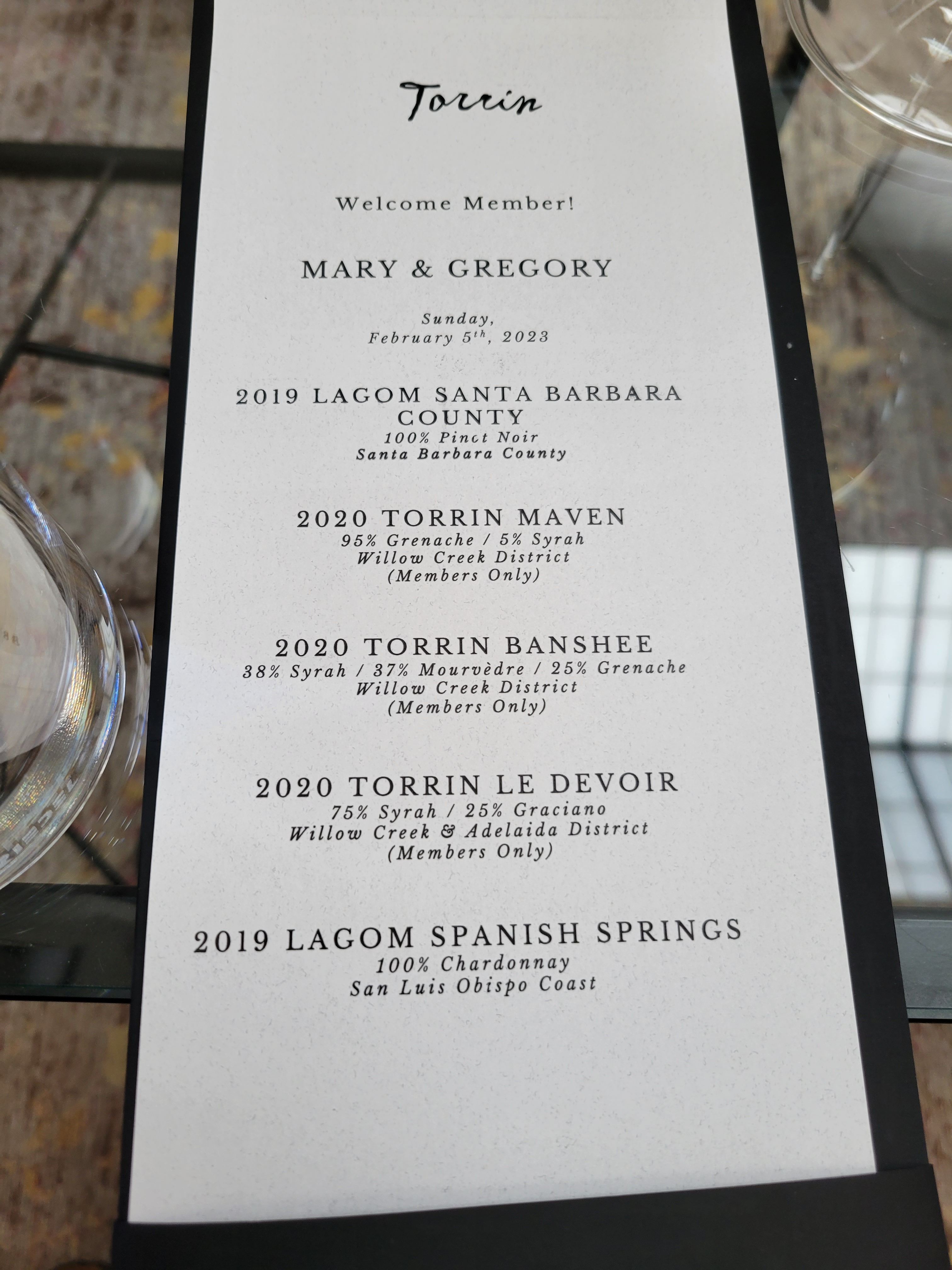
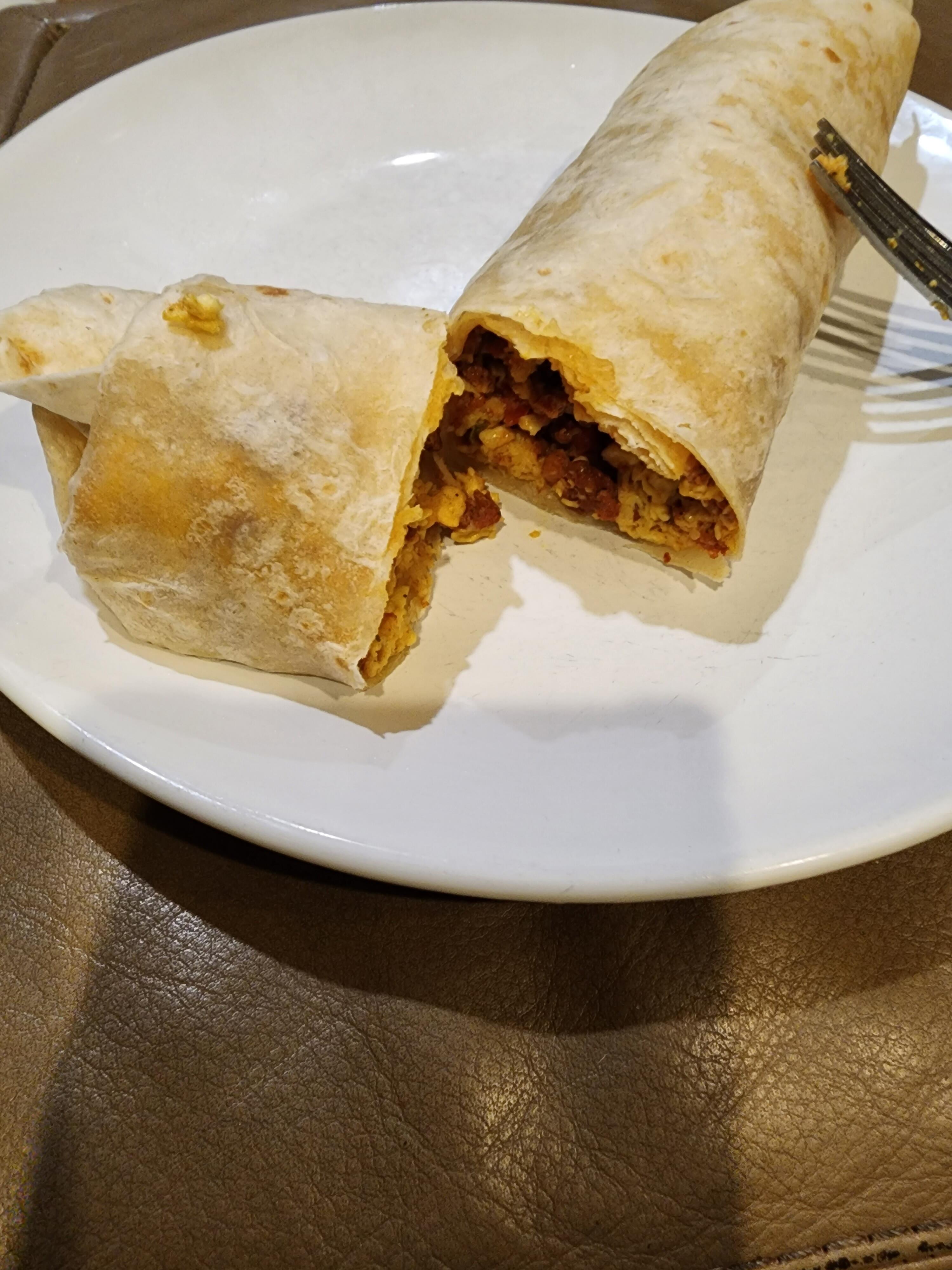
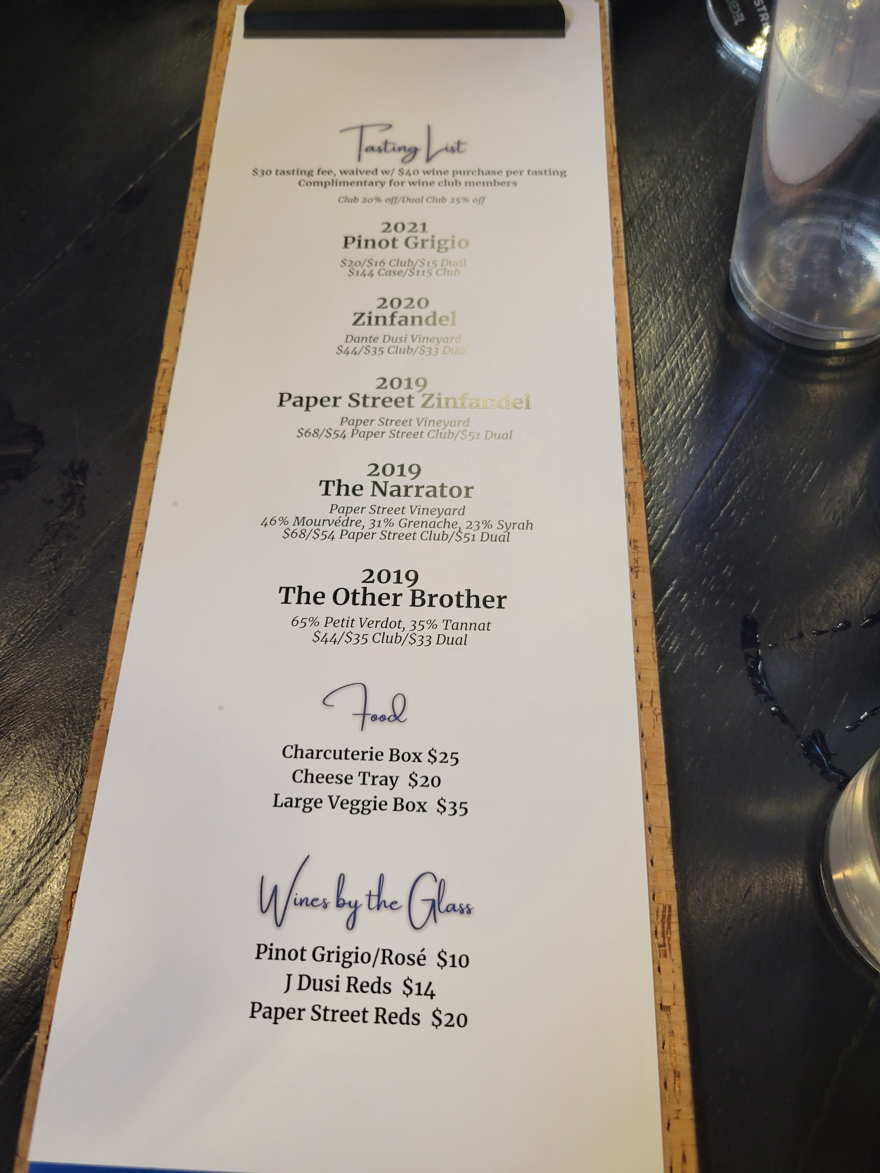
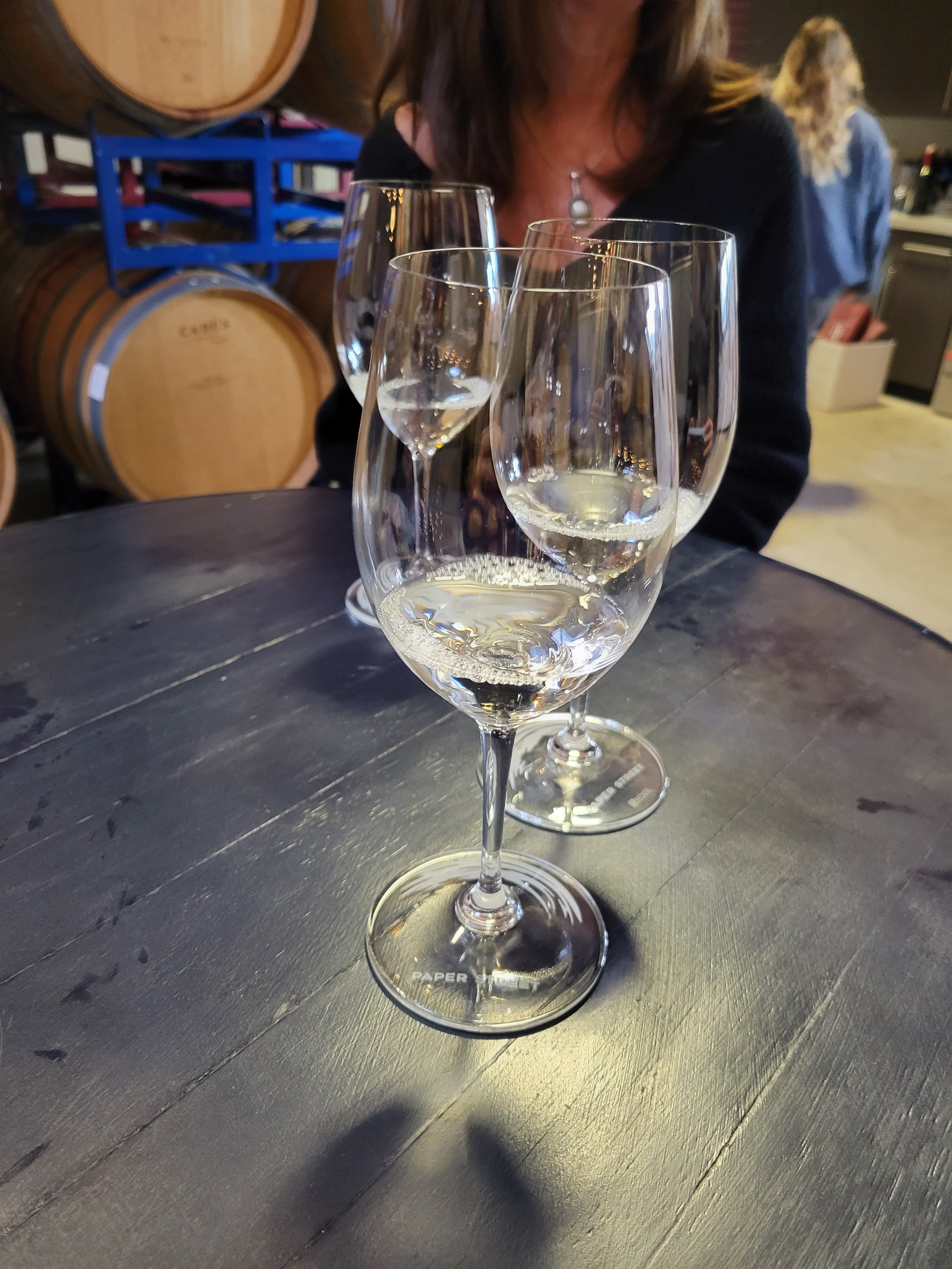
5 pointsAs if we did not have enough winetasting, we enjoyed this great single vineyard Burgundy with dinner
 5 points
 -
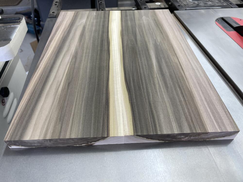
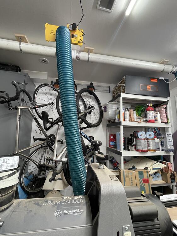
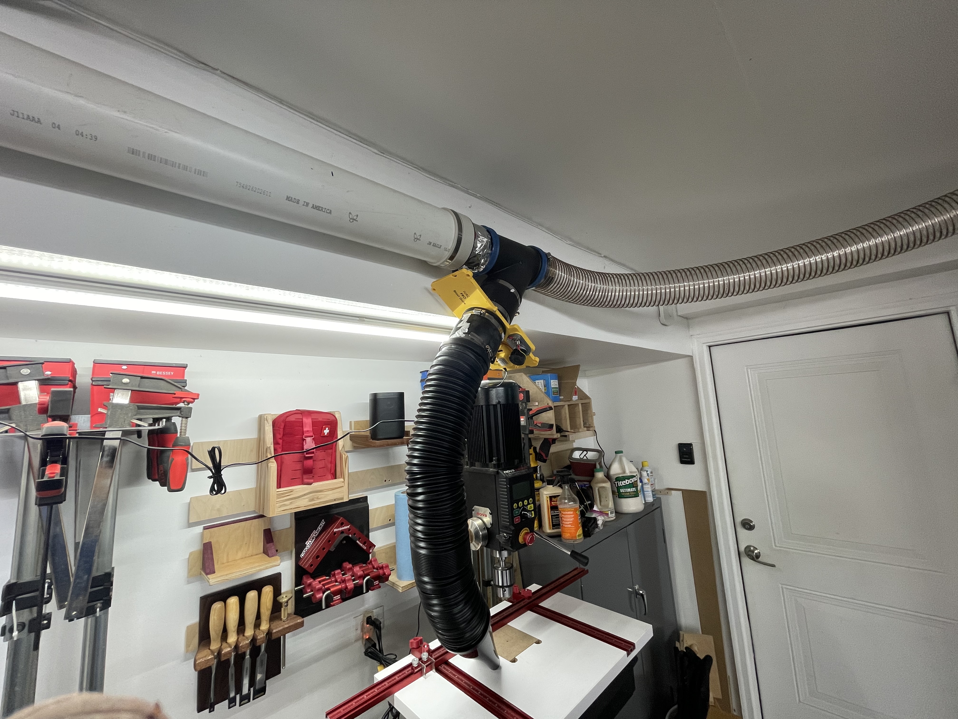
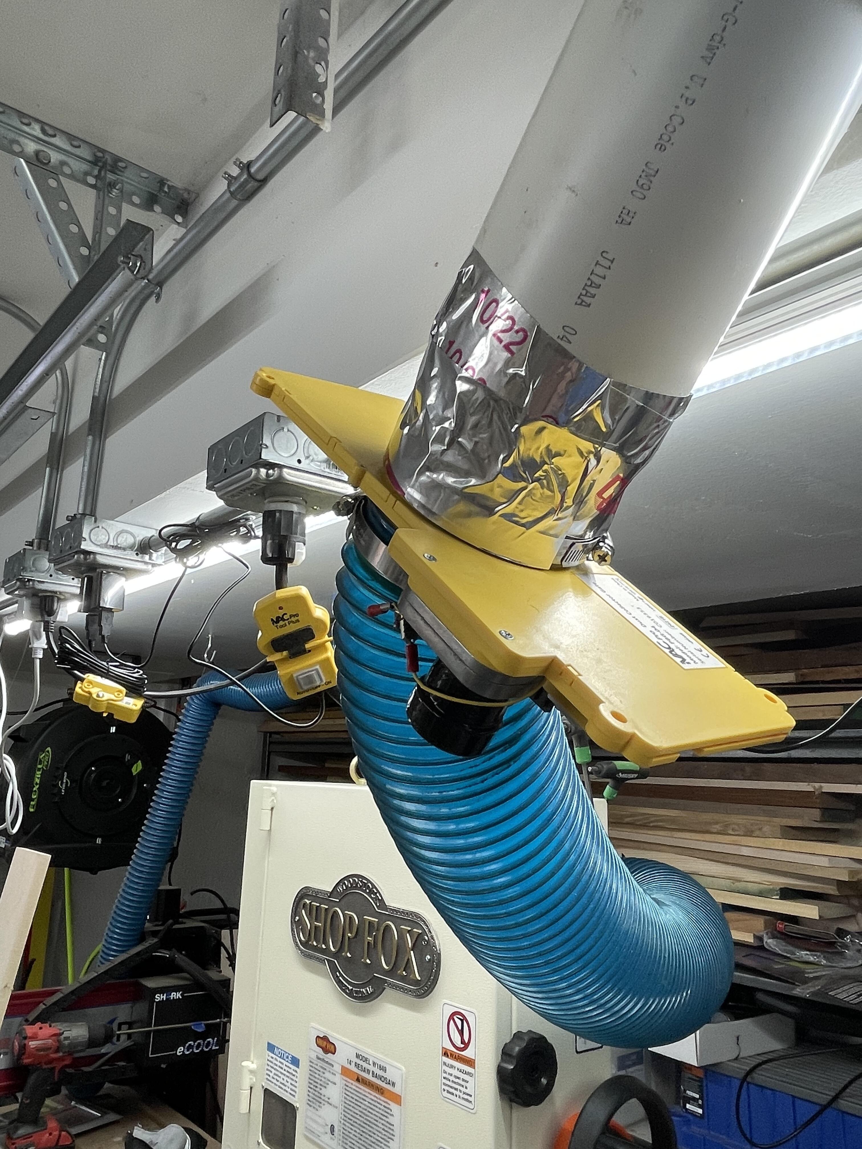
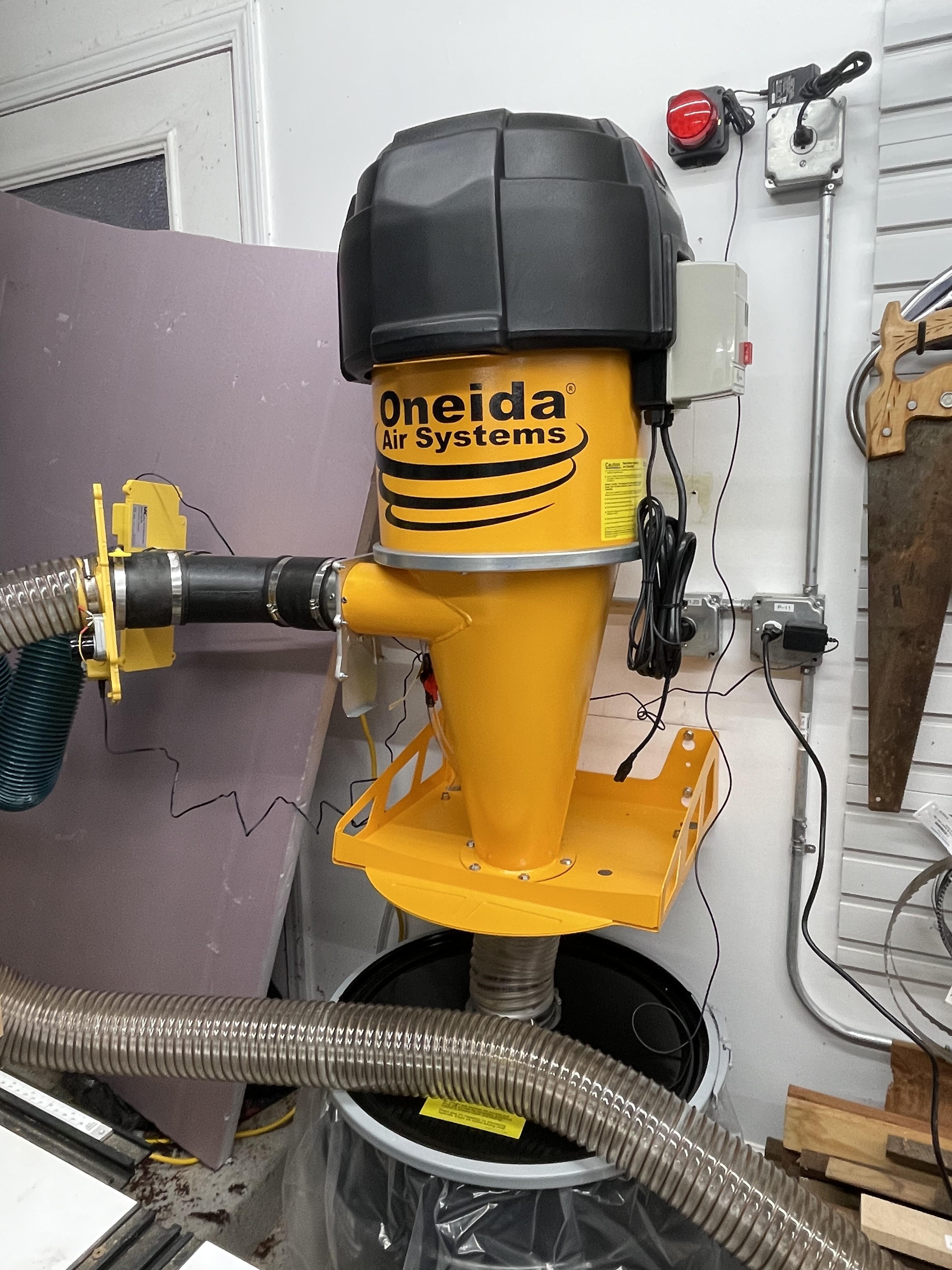
5 points5 points4 pointsGot up at 3:30AM to get to Boston to catch a plane. Next stop, left coast and the Navy Post Graduate School.4 points3 points3 points3 points^^ What a prude. First day of actually using the Oneida Supercell Turbo thoughts: 1. Loudest tool in the fucking shop. 2. Remote is super shitty and too small. Will need to buy 12 to stick them to every tool. Also needs direct line of sight to the unit. 3. Due to needing the hose mount on the left, my filter cleaning bar thing is on the back and kind of a pain in the ass to operate. 4. Jointing and planing two small boards with a couple of cuts on the table saw has almost half filled the 35 gallon drum. I have not figured out how to determine how much better this system is than the previous, but it seems to me to be less dusty in the shop than usual. Picture of the two boards ready for glue up for interest.
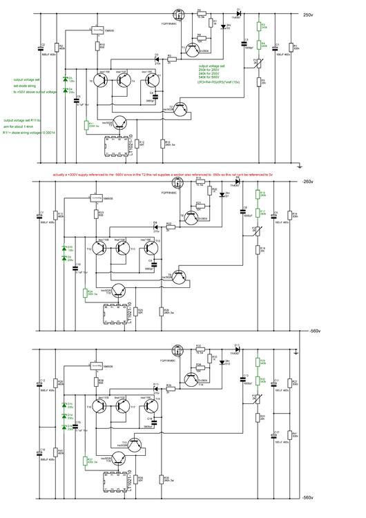
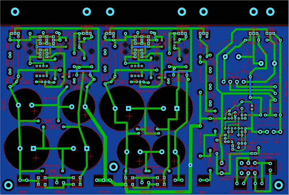
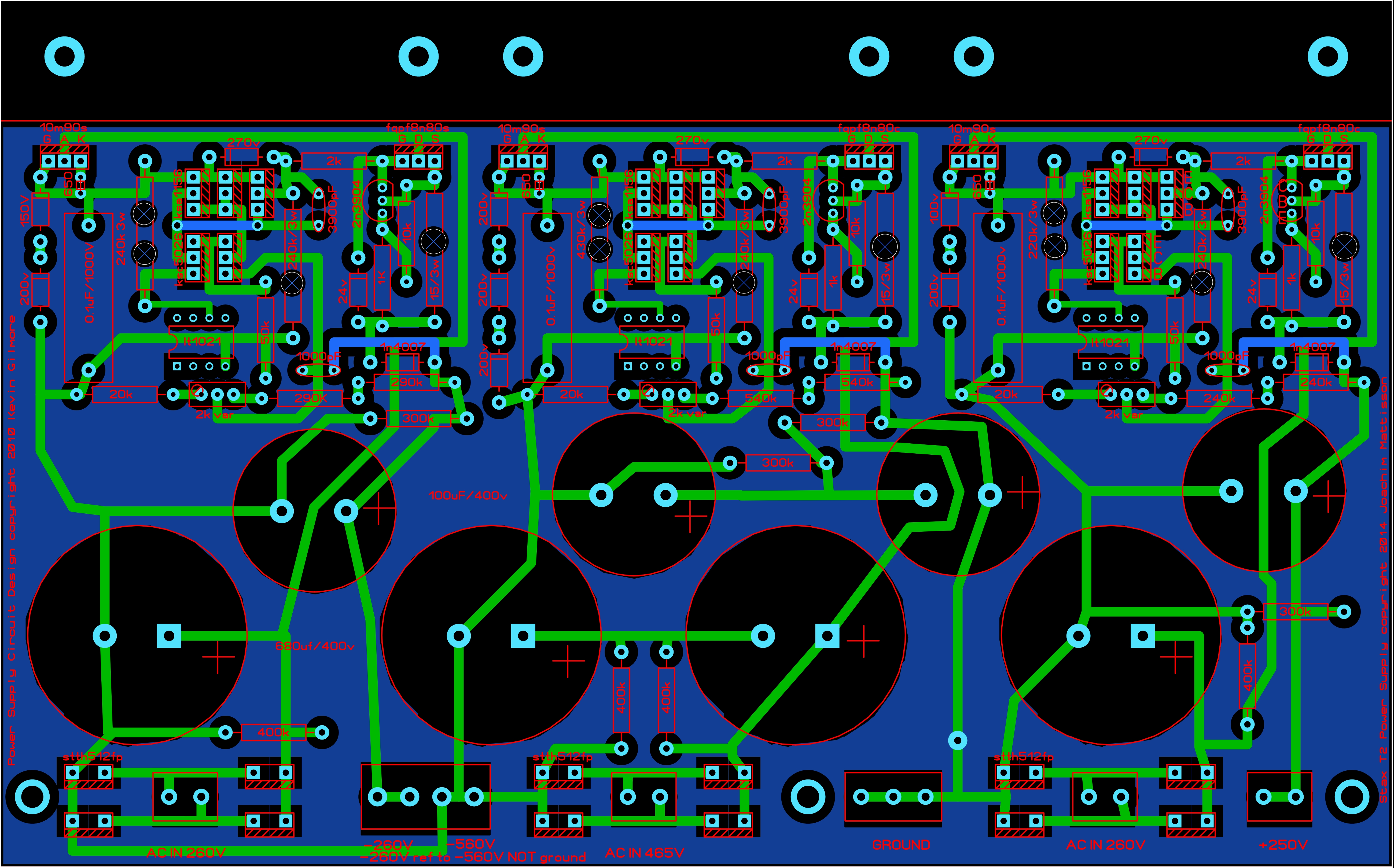
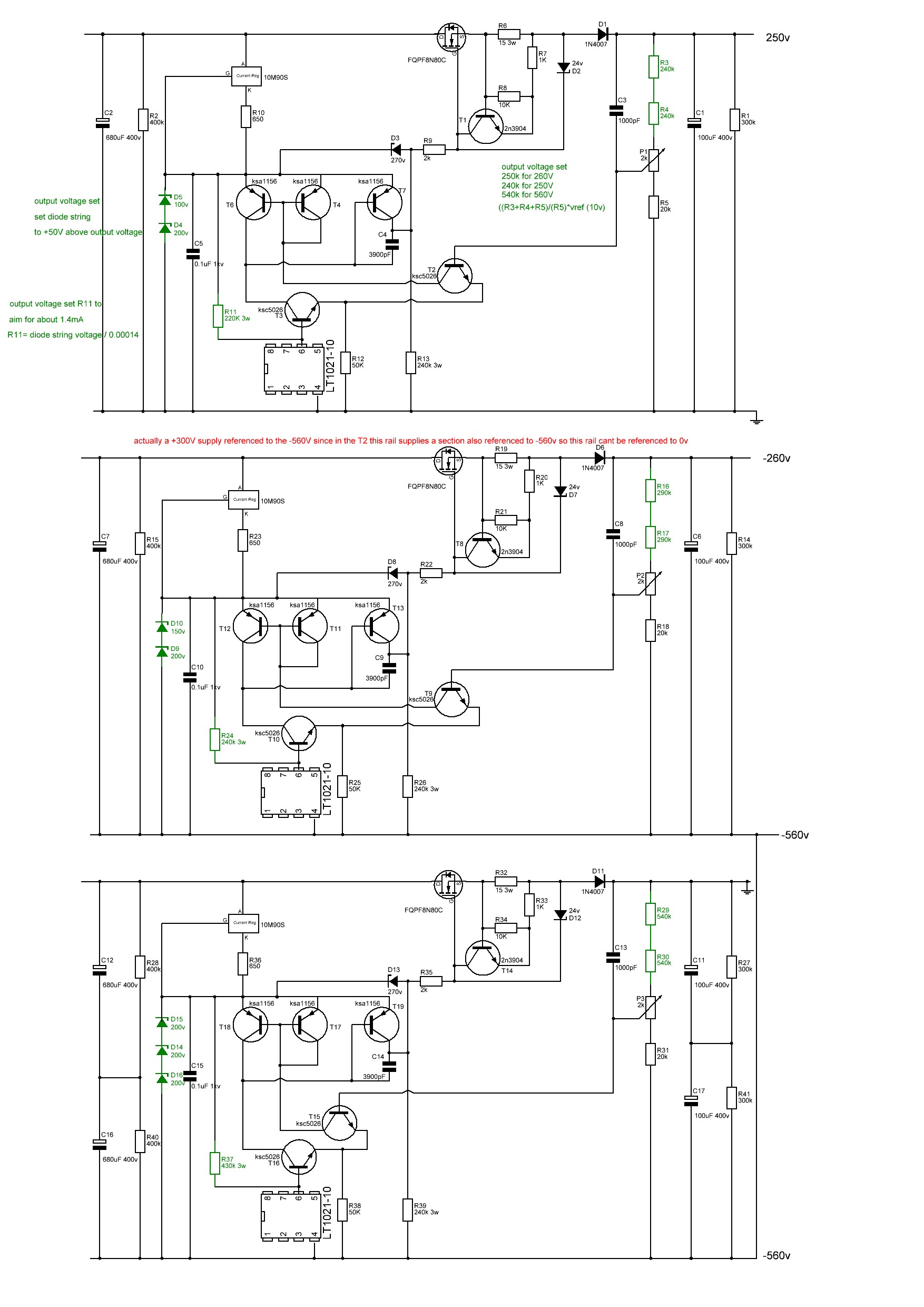
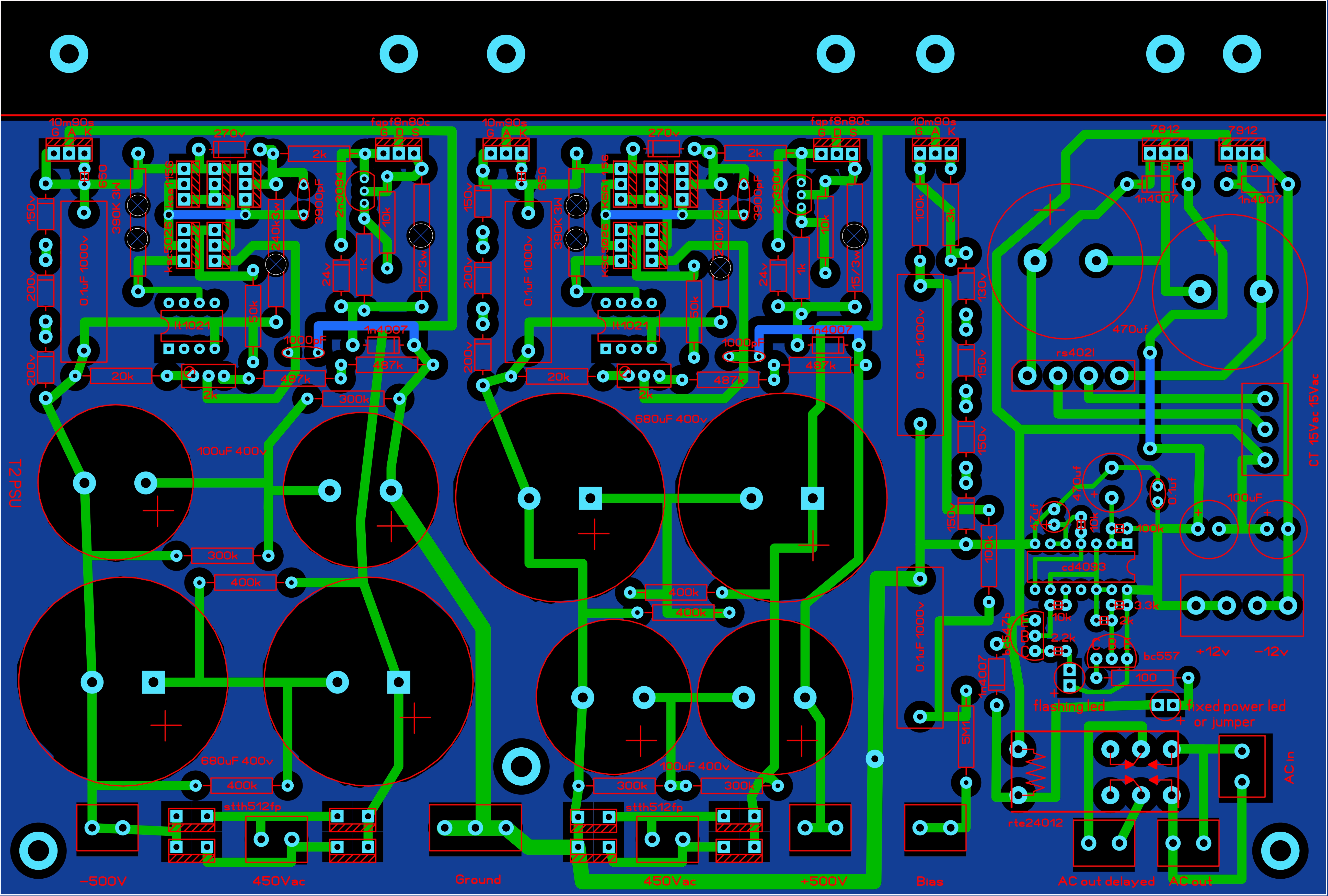
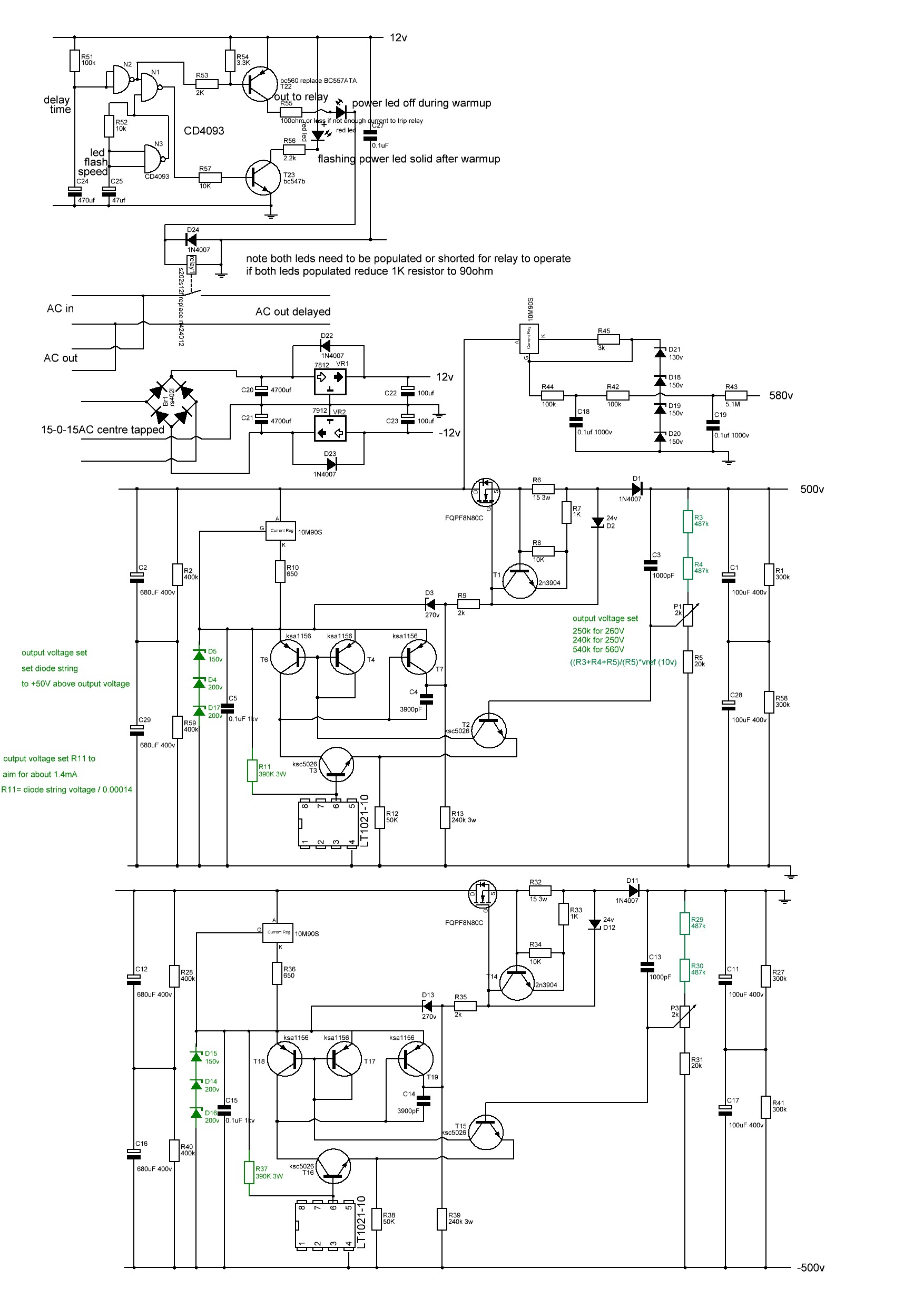
 3 points2 pointsR11 determines the current through LT1021-10 which needs 1.1 mA at 25 degree C. Choose R11 value accordingly. For +/-500V sections; R11 = 400K gives 1.4mA and 0.8W.2 points2 pointsHere the latest T2 psus, I have modified the layout to provide more space around the rather hot R11 3W resistor and added vent holes to the pcb. The pcbs, transformers etc still fit inside a 400mm deep case without issue. I noticed that the R11 equivalent resistor on the + and - 500V rails runs considerably hotter than the equivalent resistor on the other rails (which also run quite hot).... doing some quick maths, R11 is approximately 1000ohms * the value of the zener serial train /1.818 on all the psus rails except for the +and -500V... Using this formula gives 300Kohms for the + and - 500V rails but in the original gerbers I worked from only have 240K there. This results in higher current flow through the resistor and more power dissipation and hence the higher temperature. EDIT: thank you Joamat for suggesting the current through R11 should be 1.1mA or more. The R11 values here on all rails are based around 1.4mA with values available in the PR03 Vishay range or 3W resistors. Resulting in lower power dissipation on all rails and especially the +-500V The gerbers with the vents have been used to make functioning psus and can be considered tested. This pcb is 220mm wide by 137mm deep and contains the -260V, -560V and +250V rails t2 kgsshv 250v -260v -560v corrected.zip ---------------------------------------------------------------------------------------------------------------- This pcb is 220mm wide by 148.5mm deep and contains the low voltage rails, delay and the +-500V rails with the adjusted 3W resistor t2 kgsshv +-500v, lv, bias and delay corrected.zip
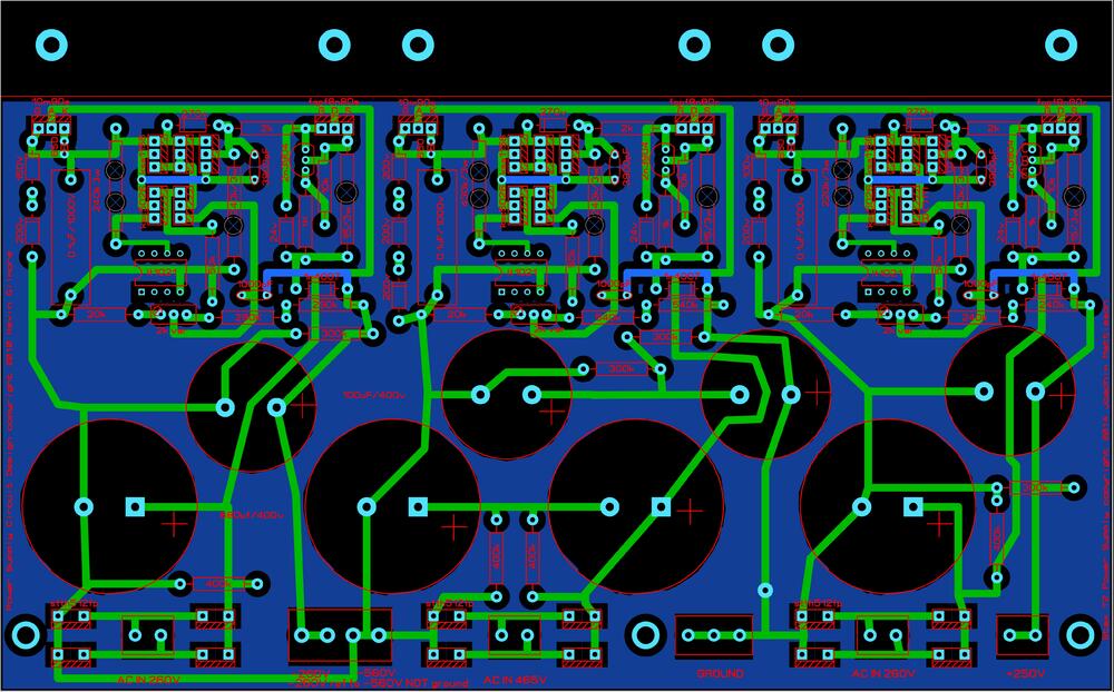
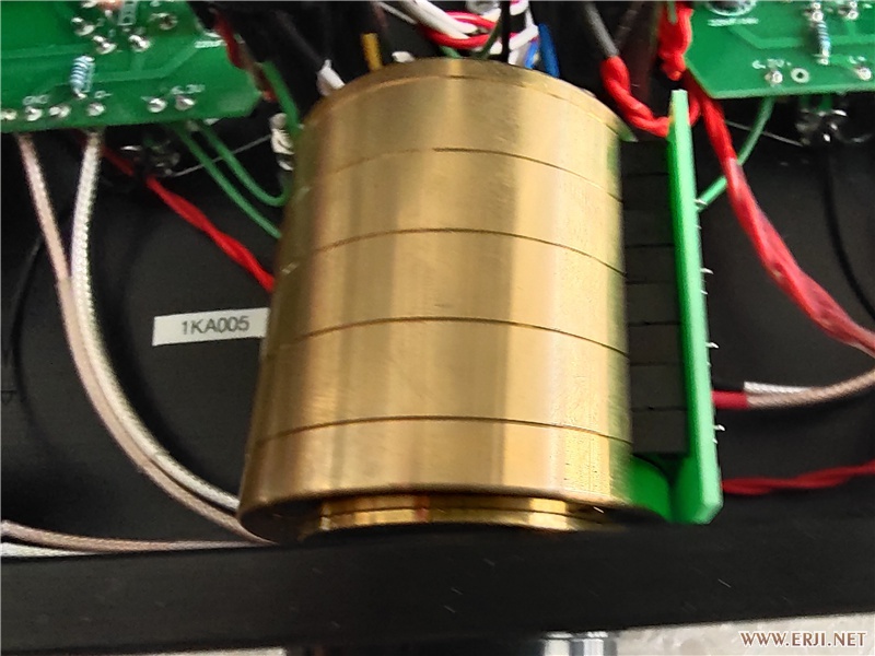
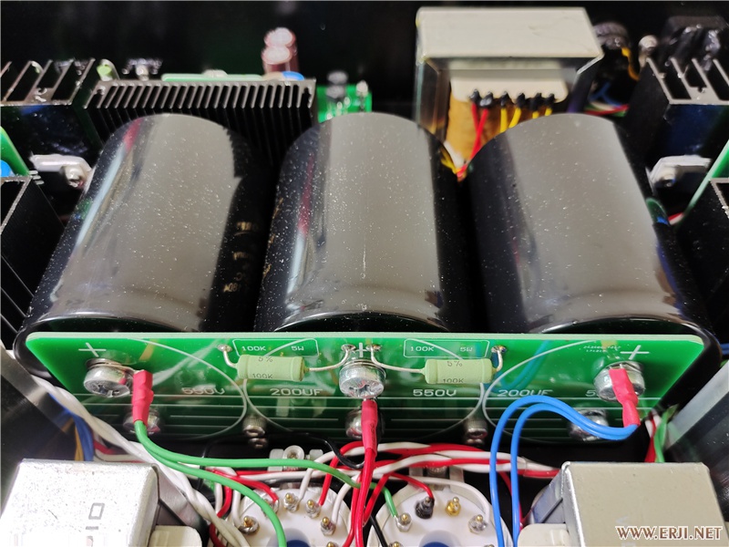
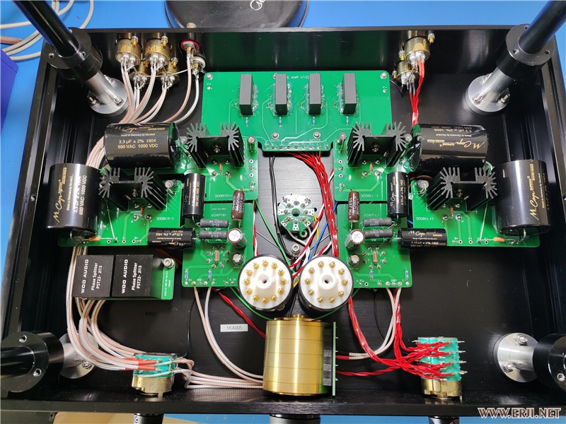
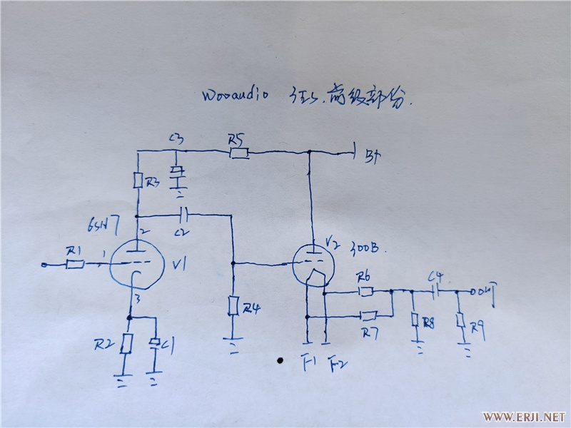
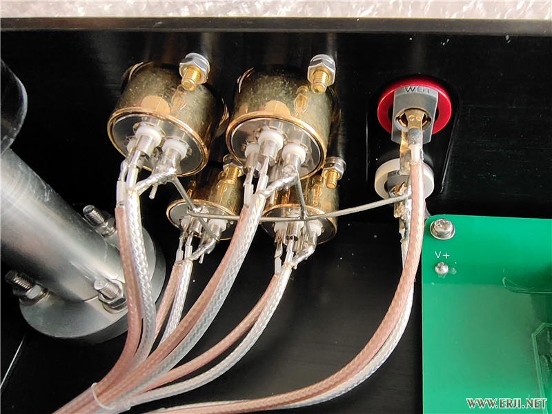
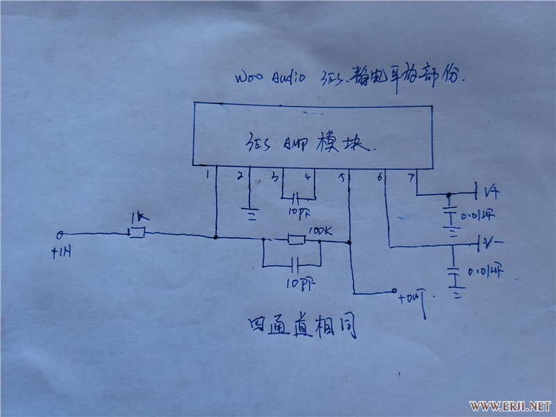
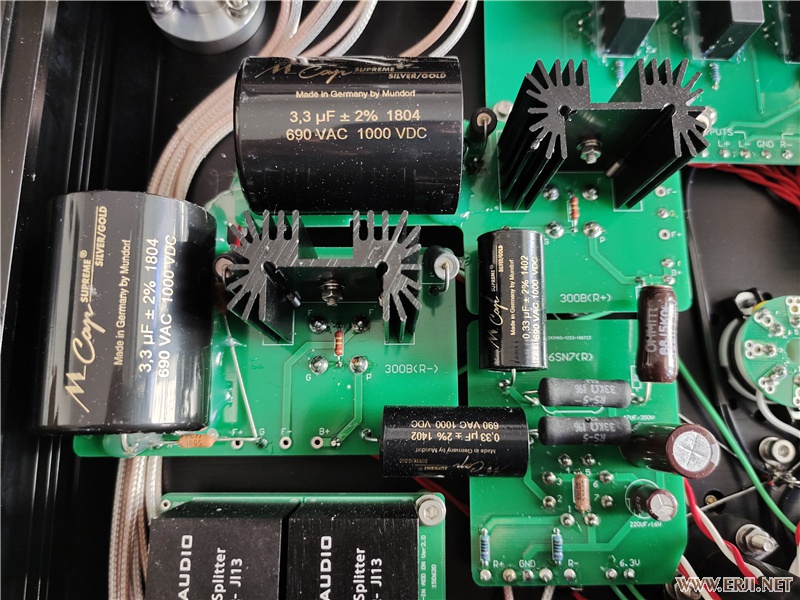
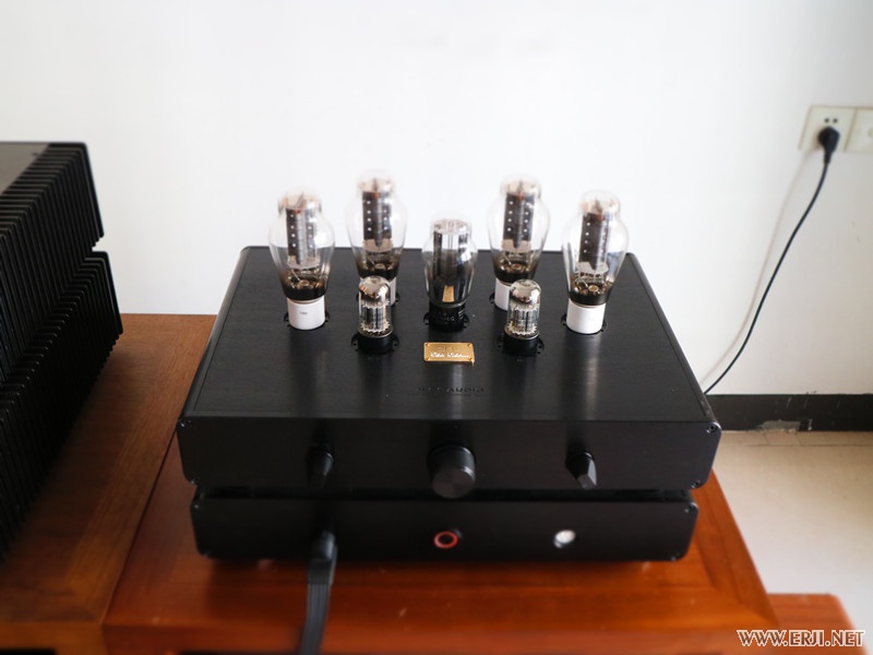
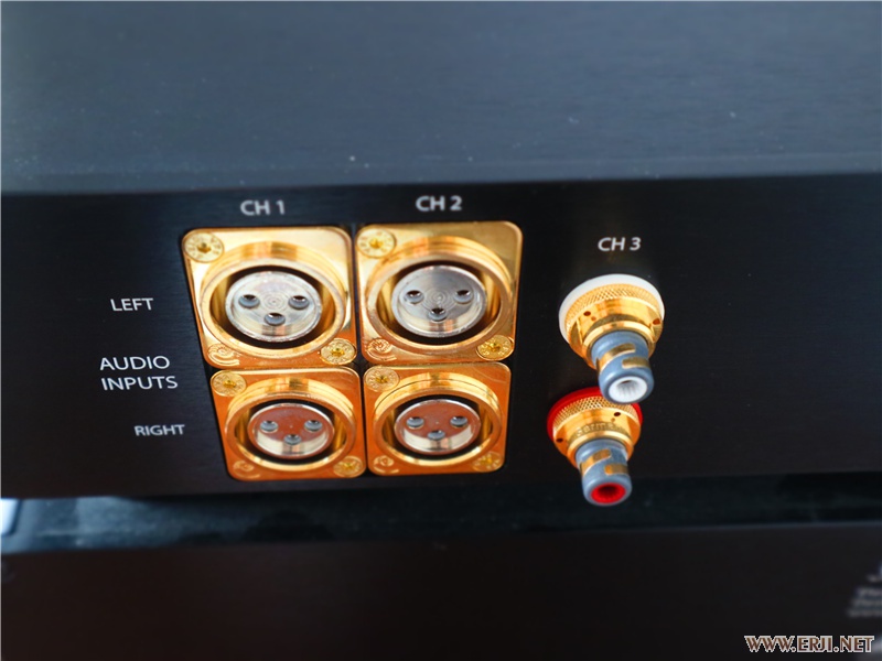
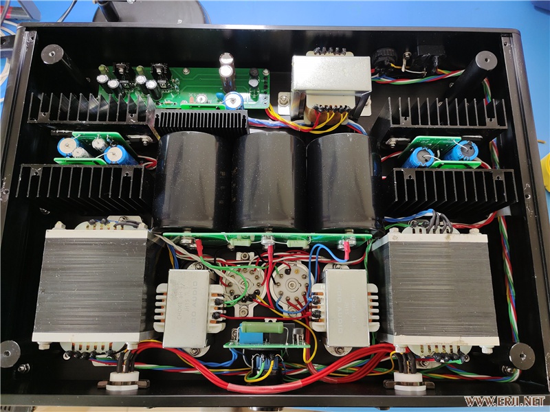
 2 pointsShe is fast - but happens to be very good as well. Ed: Also, isn't that three things?2 points2 pointsGive this guy a billion dollars and he will complain about all the zeros.2 pointsThis week I was browsing the net and I came across this: http://bbs.erji.net/forum.php?mod=viewthread&tid=2239622 Now it is all in Chinese but these were the first pictures of the insides of the Woo Audio 3ES. This was an amp I never really paid any attention to, I'm so fedup with Woo and their sub-par crap, but finding internal pics does warrant a look. First off the pics aren't great but at least there are some schematics there and we need to try to verify they are correct. We have no further info than this as I can't find any more internal pics, so this is what know at this point. First the PSU: Now, nothing new here, same old crap Woo have been building for years but why place the output sockets right next to the power transformers like that? I mean the whole idea behind a two box solution is to place the noisy power transformer away from the amplifier and thus the output, not run the signal back into the PSU and have the output sockets right next to the, rather large, radiation field of the EI power transformers. Makes no sense but things are about to take a turn to the worse: Now... here is where things start to look a bit off and I'm going to see if anybody can spot it without venturing further. Now neither Kevin nor I can read Chinese so the markings on these two schematics that were included meant nothing to us: We focused on the tube schematic and wondered how this could work, I mean it is a simple grounded cathode 6SN7 input with a 300B cathode follower output. We are not dealing with a lot of gain here so at first the schematic had to be wrong, no way to drive electrostatics from this. Then Kevin figured it out, this is just a preamp, the latter schematic is the output for the headphones and what is that... it's a fucking Apex PA97 opamp!!! https://eu.mouser.com/datasheet/2/156/pa97u-1853045.pdf Go on, double check the pinout against the datasheet and look at the recommended values. Now look at the internal picture again and follow the wires, input selector is on the left and the preamp/headphone selector is on the right with the red wires. What's there next to the back panel with 4 identical modules and a shit ton of hotglue? The electrostatic module... which is made up for 4 of these which cost around 100$ each in bulk. This is a 14k$ amp! Now we don't know what is on the heatsinks next to the tubes, has to be a TO220 size part but no way to see what it is. The rest of the schematics make sense though. B+ goes directly onto the 300B plates and there is a grid resistor next to the "G" pin with the cap from the 6SN7's right next to it. Two large resistors next to each filament pin too. Then we have the large, brown, resistors going off the B+ to feed the 6SN7's and two identical plate resistors for it too. . Now what is the problem... well I can't see anywhere on the Woo site which says this is a hybrid amp, they talk about the 6SN7's, 300B's and the rectifier but nothing about a basic opamp outputs for the electrostatic outputs. Let's just quote them: "The new 3ES achieves the most ambitious dream in the audio world". Yeah... not so sure about that... Funny enough, clones of the Stax D10 are surfacing in China now and I have one. Guess what that one uses? Apex opamps.... and I bought one for 250$ shipped to me and it fits in the palm of my hand. Below are the rest of the pics from that Erji post for posterity.
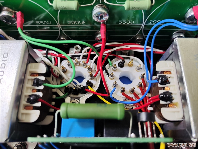
 1 point1 pointThe original published gerbers has All the rails running at around 1.8mA through the R11 resistor except the +-500V rails at almost 2.3mA! The original published gerbers has: +250V rail (300V zenner string) using 160K so 1.875mA, 0.56W -260V rail (actually a +300V supply (with 350V zenner string) ) using 200K so 1.75mA, 0.61W -560V rail (600V zenner string) using 330K at 1.82mA, 1,09W +-500V rails (550V zenner string) using 240K almost double the required current at 2.29mA... and around 90C+ temperature with the lid off dissipating 1.26W... so if we set a target of around 1.4mA to provide a little headroom and go for values in the vishay PR03 resistor range available at mouser or radio spares: +250V rail 220K (available mouser and radio spares) for 1.36mA 0.41W -260V rail 240K (available mouser) for 1.46mA 0.51W or 270K (available radio spares) for 1.3mA 0.45W -560V rail 430K (available mouser) for 1.395mA 0.84W or 470K (available radio spares) for 1.28mA 0.77W +-500V rails 390K (available mouser and radio spares) for 1.41mA 0.78W... that's half a watt reduction in dissipation 🙂 compared to the original published gerbers. These lower dissipations might even allow the use of Vishay PR02 2W resistors instead of the 3W... time to update the gerbers and schematic again. I will update my gerbers and schematic post.1 point1 pointThat is fucking impressive. The 4” hose will knock a house off its foundation if you don’t watch where you swing it. I assumed I could connect train cars with the fucking 6”. No idea how that could even happen, but I will be watching for the flashing red light.1 pointNo, not really. "3." was just incorrectly placed, as I CBA to find the "therefore" symbol. I fixed it for you. (not entirely -- the indenting is still fucked up. ) EDIT: okay, now I really fixed it She's amazing. I've seen her live. Pretty sure she has tied Alice Sara Ott and outpaced Hélène Grimaud as my favourite living pianist.1 point1 pointAlso want to point out to Mr. Positivity that the hearing protection hanger I printed is still going strong. It did not, in fact, break within a week. Which dust collector do you have? Did you buy all the extra shit to allow the iVac remote to work with a dust collector with magnetic power switch?
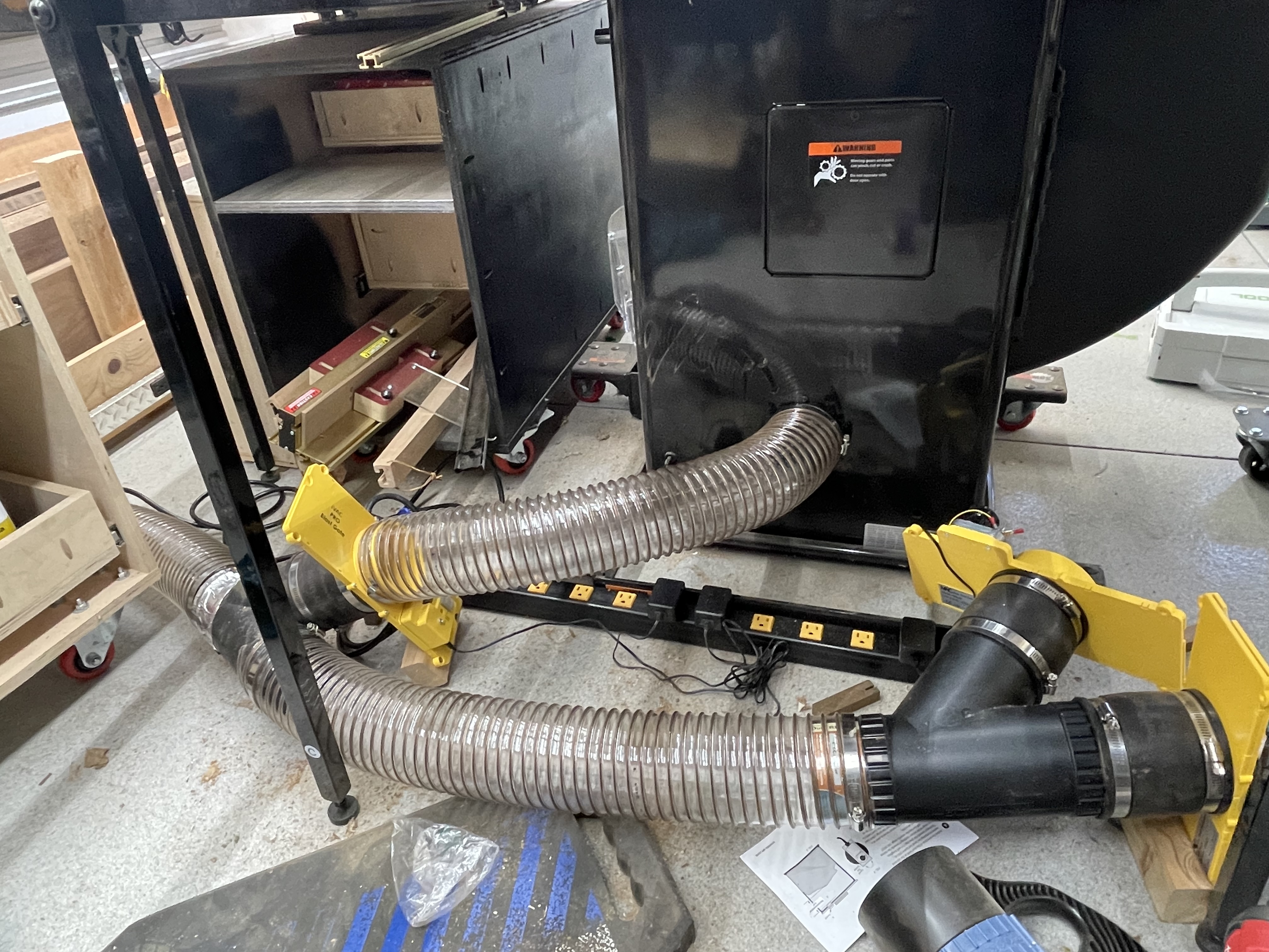
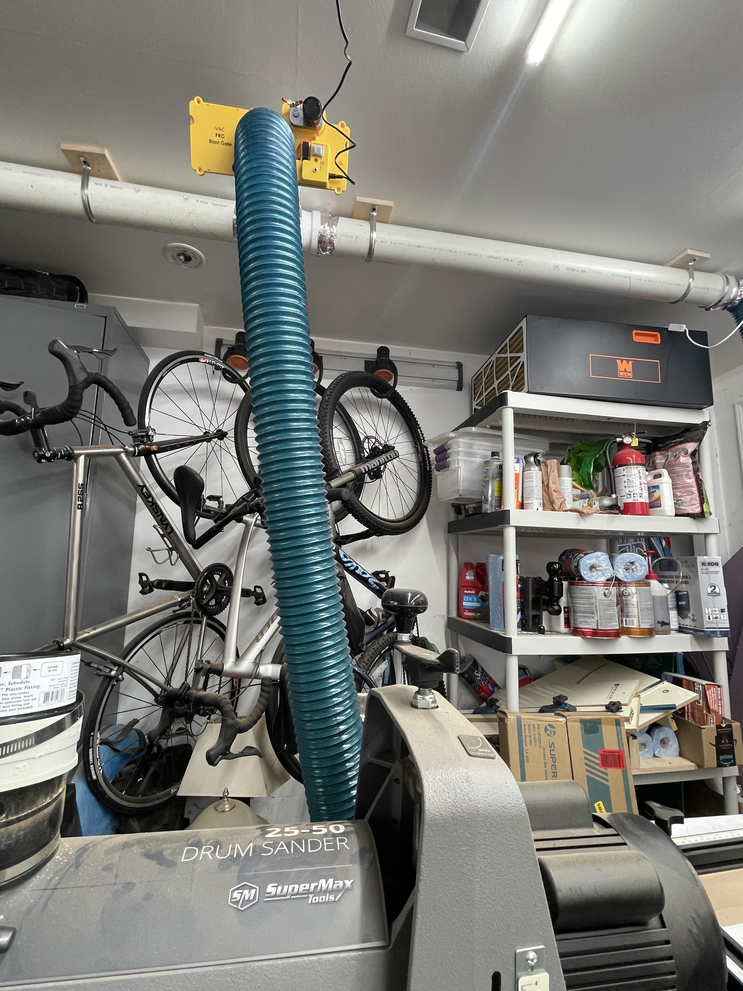
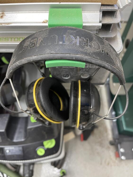 1 pointTwo things: Beato recently posted this video: I've been programming (in Go(lang) and Python), as well as taking a lot of video lessons in programming, so I need music without vocals, so... ∴ I've been listening to a lot of Yuja Wang.1 point1 point1 point1 pointFinished the dust collection system revamp. Ended up needing just about every one of the 700 outlets the electrician added to my shop just to power all the iVAC pieces. Even managed to use the seriously heavy duty hose without seriously injuring anyone. Need to come up with a way to reinforce the barrel lid as the bang on startup and shutdown is annoying.


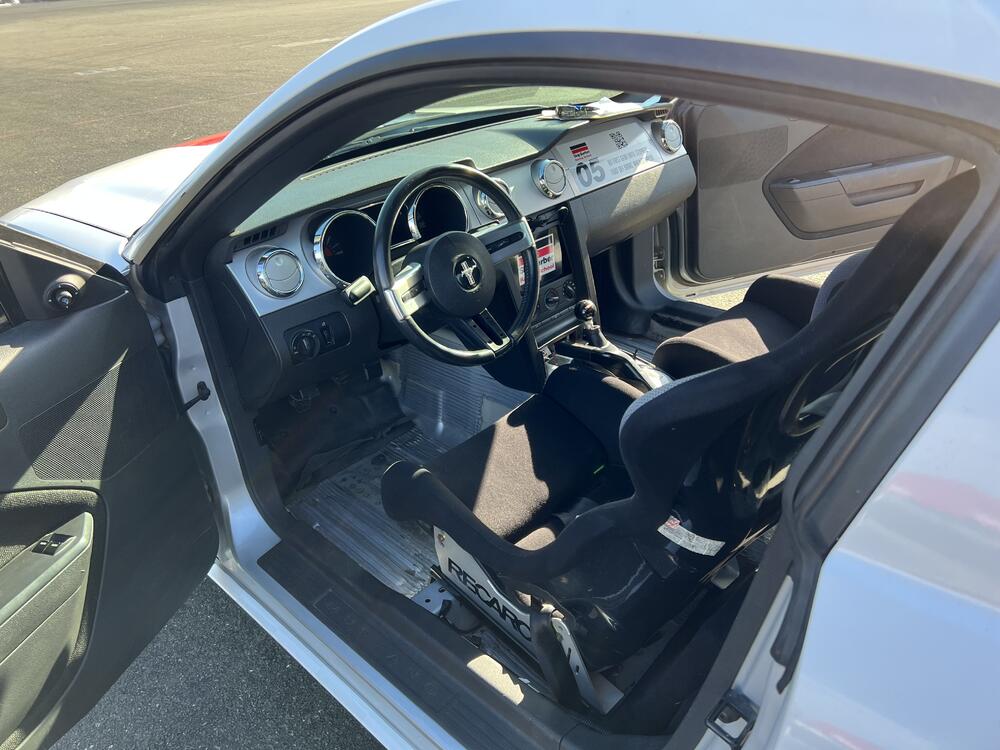
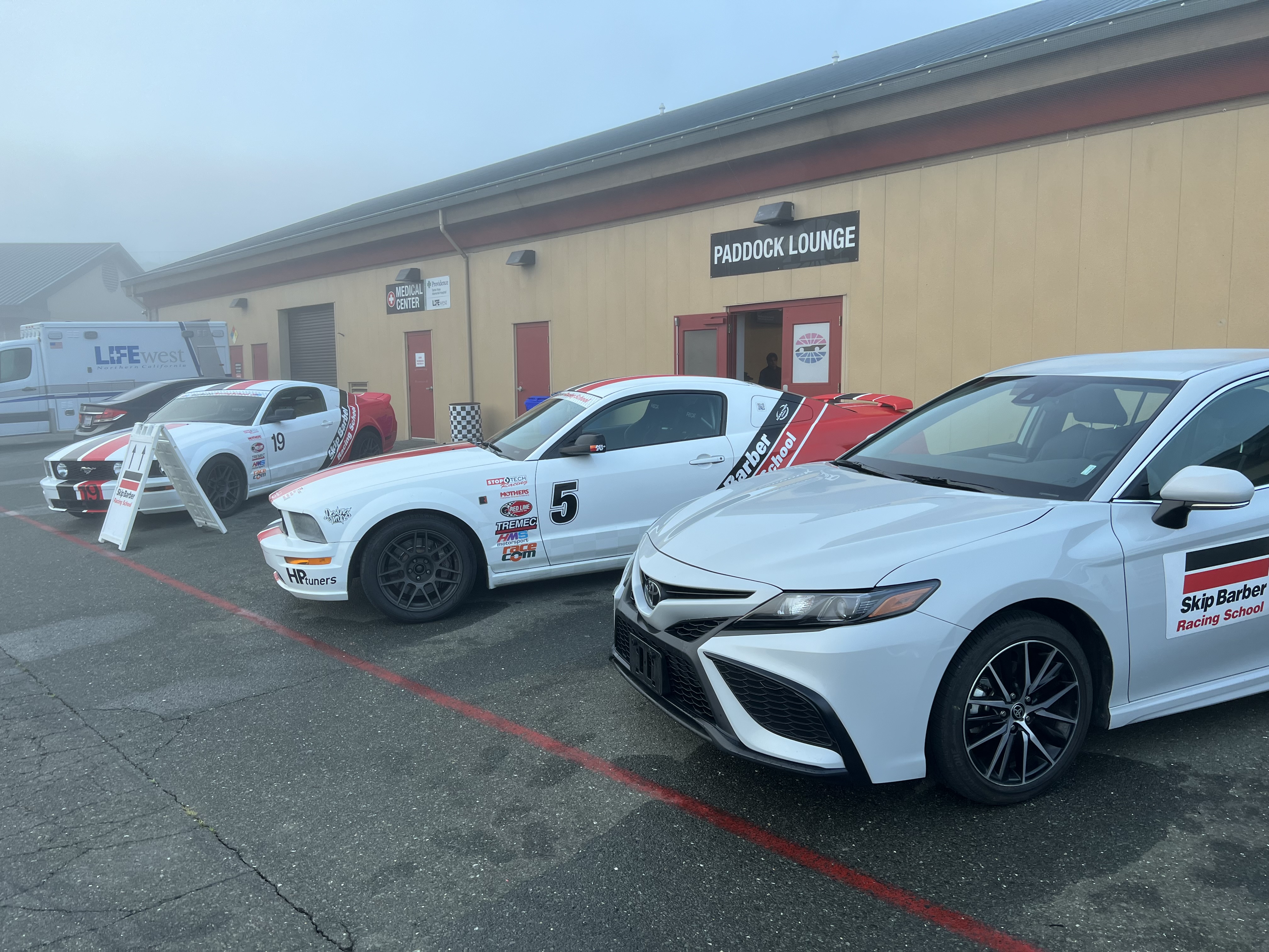
 1 pointI'm taken aback a bit with this one. Kind of a paradigm shift for me. One of the most badass songs ever? Or is it the 9% IPAs I've been drinking? No i think this is really fucking good1 point1 pointI learned a ton and had a blast at my Driver's Academy class on Saturday. There were 24 students, about 16 of the 24 were teens and young-twenty-somethings and the other 8 of us were older drivers. For the 24 of us they had 6 cars and 6 instructors, so we were four to a car plus an instructor. The day was almost entirely cone drills and was all about car control. While car control is obviously important to the enthusiast, I really do think this is a class that anyone could benefit from. Knowing how to handle your vehicle in an emergency like a sudden lane change, slide, or emergency braking situation is something all drivers should know. Getting to learn these skills on a closed course in a safe environment rather than doing it for the first time out on the public roads under duress is tremendously valuable. I think auto insurance companies should offer discounts or subsidies towards paying for one of these types of classes. They really are that beneficial. As an experienced driver I found that while I intellectually know what a lot of car control theory is, there is a difference between knowing it and being able to execute it while under stress. There is also a "feel" component to things that a video game or simulator just can't replace. A lot of driving at the limit is being able to feel what the rear tires are doing through the seat. It was great to be able to ride along as a passenger while the other students were getting instruction. Not only could you soak in what the instructor was telling them, you could feel through the seat what the car was doing. The difference in feel between doing something the right way and the wrong way is really something you have to experience in person. Most of the drills were done in normal cars. Camry, Altima, Malibu, CLA250. Tires were shitty all seasons. All drills were done with traction and stability fully off. I think the idea behind this was you can find the limit at much lower speeds than you could in some of the race cars they had. It worked great. Driving a slow car fast is a heck of a lot of fun, as always. We cycled between three drills in a morning and an afternoon session. In the morning the drills were: Skidpad (my favorite!) - Go around until the car understeered, learned how to handle understeer. Then oversteer. Get a feel for how to catch it, what it is like to not catch it and spin. I was good about counter steering but I needed to learn to wait until the rear end hooked back up before correcting my steering input. ABS emergency brake + maneuver - Do a full ABS slow down and then maneuver to avoid hitting a "wall" of cones. I was familiar with doing ABS stops but adding the maneuver element to end was a new twist. Under full ABS all the available traction is going to braking so if you don't lift a little on the brake you are just going to understeer and plow in to the cone wall. Proper cornering - they had a hairpin turn set up with cones. Drill was to trail brake in, hit the apex, power out as you unwound the wheel. Hairpins are hard because everyone's natural tendency is to turn in early. The apex on a hairpin is well past the geometric center of the curve, so this drill was all about eye training and visualizing your line. It is amazing how much speed you can carry when you get the line right. Afternoon drills were: Introduction to autocross - They took the hairpin in the morning session and added a bunch more corners to make an autocross course. I loved this. Taking it slow at first and then building up speed on consecutive laps felt great. Emergency Lane Change - Speed towards a cone wall with a lane to the left and right of it. A second before you get to the wall the instructor shouts "left" or "right" and you have to make an emergency change to that lane, then slow the car. Scariest drill of the day, as you feel like you could roll the car. Doing this kind of emergency lane change at 45mph felt extremely FAST, but we built up to it. Driving a Manual Transmission Car - I basically have never driven stick before ever, but I know how things are supposed to work. We did this one in the Mustang race cars they had, which was fun. After stalling once I got a feel for how heavy a race clutch is. After that it was pretty simple. I don't think I need to go out and buy a car with a stick, but I get the appeal. On the whole, an awesome day. I feel like I learned a lot and it was the kind of learning that I only get by actually doing the thing. As I said before, I'd recommend this kind of Driving Academy or defensive driving class to anyone. It was pricey, but worth it. Instructors were great and we got plenty of seat time.
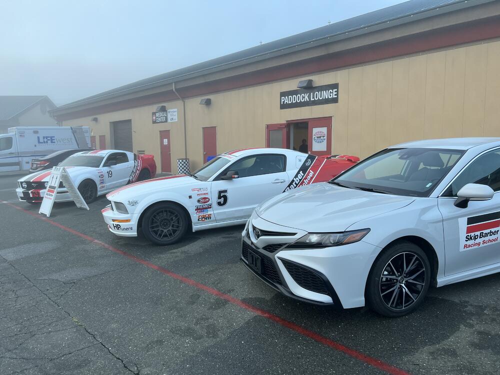
 1 pointNow all we need to know is when CDs will sound better than records ...1 point1 pointPBHV2160Z is nice due to its high HFE and low Cob. I'll be using PBHV2160Z and PBHV3160Z in my upcoming GRHV build with off-board e-caps. From simulations using those transistors I learned that C5 needs to be increased to 15pf to 22pf for best phase margin, and 47n is still the preferred value for C4 that provides a low and consistent output impedance across the audio frequency range. Another interesting find is that the circuit needs about 100uF output capacitance to be stable, and increasing the value of that cap has a diminishing return in the performance, unless the cap has really low ESR (such as film caps). In case the cap's ESR is high, some additional compensation can be added to ensure stability (hundreds of pf across R7). The above findings are for the original GRHV with 400V output. YMMV if the output voltage changes.1 point0 points0 pointsI'm not sure if anyone mentioned that earliier - but my all time hero of groundbreaking scifi, Greg Bear died at age 71 after heart surgery, in November. https://www.theguardian.com/books/2022/dec/29/greg-bear-obituary RIP Greg Bear0 points


Important Information
By using this site, you agree to our Terms of Use.