

Leaderboard




Popular Content
Showing content with the highest reputation on 11/12/15 in all areas
-
3 pointsNew battery arrived this evening and it's been replaced already. iFixit tools are really good, it never took me this little to open the MBP. The new battery seems absolutely legit, came half charged at 54% and is lasting a lot. OSX isn't showing the "fix battery" warning anymore. Now the trackpad click is soft, I think it's never been this soft, not even when the computer was brand new. That or my fingers have got so strong by clicking on the old battery for months that now I can drill on wood with my sole finger.3 points
-
"Can my buddy n3rdling come?" They're also having a waiting list for hearing these at CES. I emailed them to get on it but no response.2 points
-
Not going to get to the update today, will likely now do it on Saturday.2 points
-
2 pointsI'm pretty sure we made him nervous enough that he called the bomb squad and had it encased in sandbags.2 points
-
2 points
-
I like it CJ. I don't think I ever bothered posting any of my Ireland Pics. The RX-1 is an excellent travel camera. Tempted to pick up the new version ASAP.2 points
-
Quite proud of this one. A fair amount of work went into it. Doesn't look nearly as effortless as Peter's work but happy with how it turned out nonetheless.
 2 points
 -
2 points
-
1 pointThanks for joining Head-Case. I'm glad you're here. That said, you should be aware that this isn't your typical internet forum. We're not here so that you'll have another place to sell your stuff. We're not looking for people trying to pad their post counts, or demonstrate their ability to find witty things on the internet. If you've come here looking for advice on which headphones to buy, perhaps you should check out http://www.innerfidelity.com. Tyll Hertsens, founder of Head-Room and long time community giant is the proprietor there, and does everything he can to ensure that accurate information is disseminated about headphones at every level. This is predominantly a place for friends to discuss music, audio gear, and whatever else tickles our fancy. We are sometimes quite rude, often irreverant, and regularly abusive. Think of it like the corner bar where everyone knows each other. Don't mistake our familiarity with each other as familiarity with you, even if you've seen our names in other locations before. Spend some time reading before you start to post. Get familiar with what is going on, and who the various people are. Don't just jump right into the fray. This is your only warning, but I hope you can participate. There's a lot of good information, and more importantly, good people here.1 point
-
1 point
-
1 pointIt really is great. I'm fortunate enough to have a family member's Xfinity sign-in information for the FX app on the AppleTV so Season 2 is available there. We also started watching Mr. Robot. I really enjoyed the pilot. One of my favorite TV writers has raved about The Americans, You're the Worst and Mr. Robot, and while I'm late to the table on the last two, he's definitely 3 for 3.1 point
-
1 point
-
The Canada shipment arrived in Tuesday. Thanks again for all your work on this. Now to figure out how to best mount these horizontally in a slightly shorter than 2U case.1 point
-
1 pointYou're the Worst. It's the best. Wildly inappropriate. Great cast. Such a fun to binge on... Catching up on Season 1 on Hulu.1 point
-
Mine arrived safely....... Thanks for all your efforts in this Soren.....1 point
-
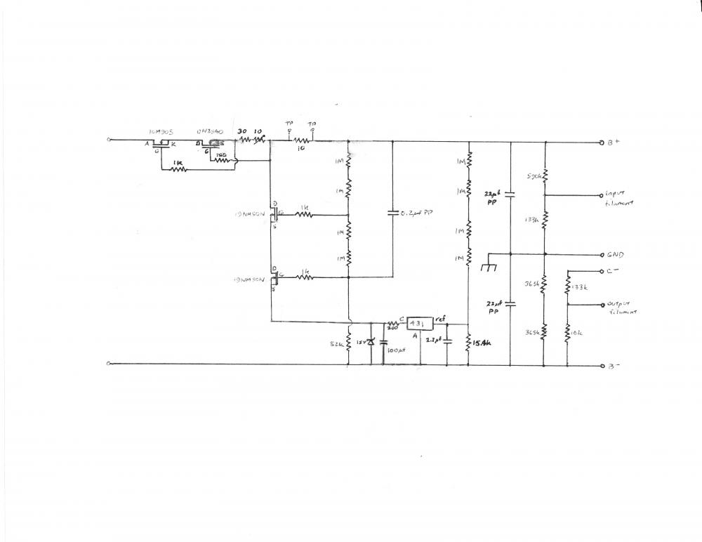
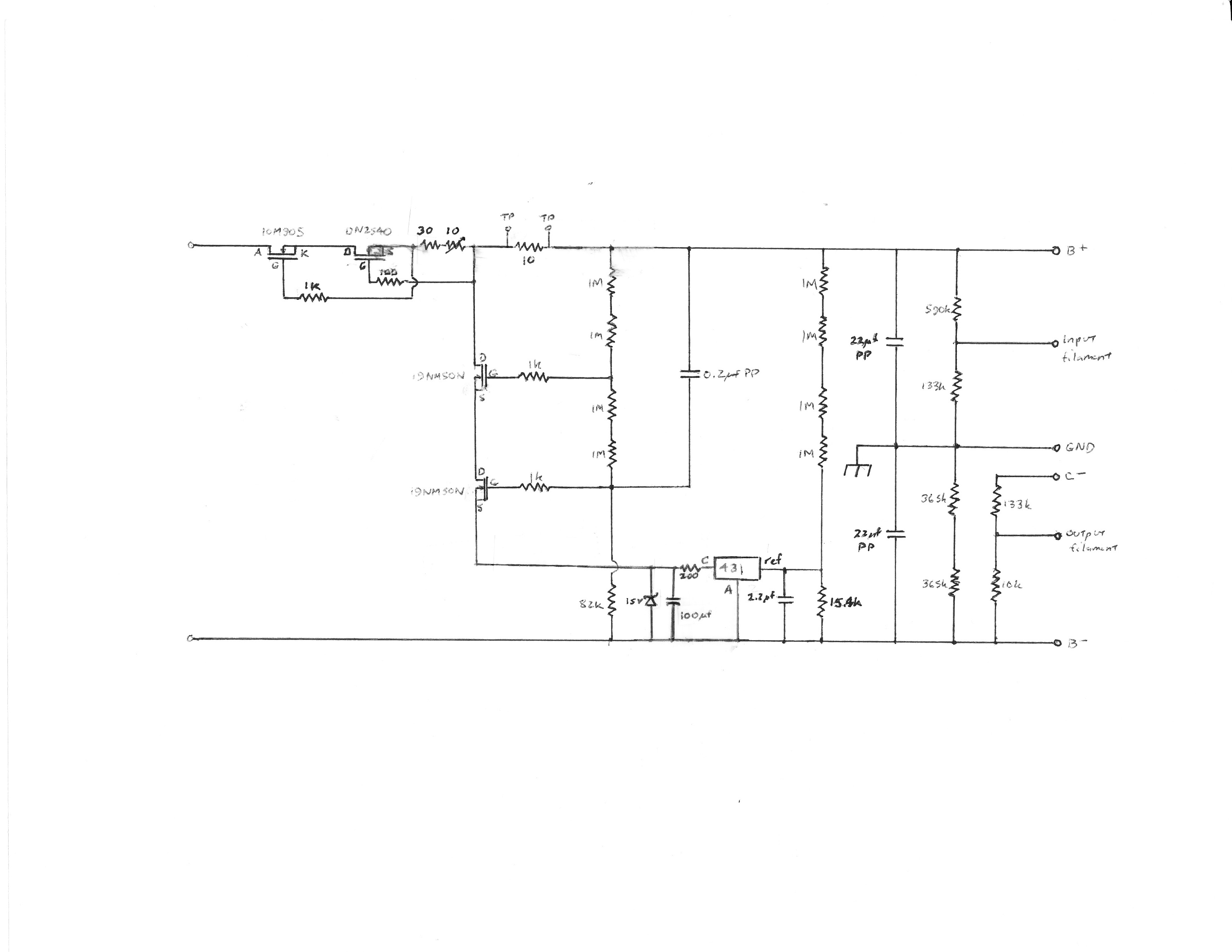
1 pointBlew out the drive and reinstalled. OSX and Windows. Both working fine now. Now I need to figure out if migration assistant will break everything or not.1 point1 point1 point1 point^ Memory foam is also very sensitive to temperature from a firmness perspective. I remember a number of years ago we drove up to visit the in-laws during the winter. My wife threw her memory foam pillow in the trunk and by the time we got there it was a brick. Took a good 48hrs+ to soften up again. I have shoulder pain with memory foam as well... doesn't seem to be the right type of support for side sleepers, not sure why it would matter, but I have never been able to get use to the Tempurpedic at my in-laws.1 point1 pointThe second part of my SRX Plus article is now published in the Dec 2015 issue of AudioXpress so I can complete the discussion of the shunt power supply. The schematic is posted above. It is almost deceptively simple, but with some neat design touches. There are dropping resistors for the input stage tail current source, resistors to set the voltages across the output capacitor, and taps to bias the filament voltages for the input and output tubes. The regulator tube in the July 1999 TubeCAD circuit is replaced by two cascoded MOSFETs. Since MOSFETs have a much higher transconductance than any triode, this significantly improves its performance with minimal additional complexity. It uses an Exar SPX431 IC shunt regulator, a temperature compensated chip with about 10 dB lower noise compared to the basic TL431, specified to sink up to 100 mA at a maximum of 30 volts – though not simultaneously, since its maximum power dissipation is 775 mW. The noise specification appears comparable to the LT1021-10. Kevin Gilmore and Linear tried to design a shunt regulator using the 431 back in 2011, however they abandoned it because of oscillation/stability problems and noise issues. In basic form it had a tendency to oscillate, but stabilizing the IC against oscillation slowed down its response significantly, making it an ineffective AC regulator. Broskie’s design addresses this problem by bypassing it – literally. In so doing, he converts the liability that KG and Linear were plagued with into a benefit, although that was not his primary intent. Sometimes, you get lucky. The raw B+ goes into a cascode constant current source (CCS) like those in the SRX Plus circuit. The total current is set by the fixed resistor and trimmer pot on the DN2540 source leg. The circuit appears to be asymmetric, but the CCS forces any current variations caused by the amp to be exactly compensated in the regulator so that the total current remains constant, and thus the current in the negative leg must also remain constant. If the amp load disappears, 40+ mA goes through the regulator, resulting in more than 30 watts dissipation. A Wakefield 421K heatsink or bigger should provide sufficient heatsinking, at least for a while. All active devices except the SPX431 are mounted on the heatsink. An adequate heatsink is very important, particularly if you use an all solid state bridge rectifier, because in that case, the power supply voltages rise to their final values almost immediately. However, since the amp circuit does not start drawing current until the tubes warm up, for 10-15 seconds all of the power supply current runs through the shunt. The shunt element is two cascoded high transconductance STP19NM50N MOSFETs buffering the high voltage to the 431 IC, with a resistor string setting their quiescent voltages and a zener protecting the 431 from overvoltages. A second resistor string for the 431 reference terminal sets the DC voltage, while the 2.2 µf capacitor between the reference terminal and B- bypasses audio frequencies above 5 Hz, limiting its function to setting the DC voltage. Broskied did this primarily so the shunt tube would perform the AC regulating function rather than the IC – but as a side benefit, stabilizing the IC will not affect the regulator’s AC performance. The 200 ohm/100 µf RC network between the 431 anode and cathode stabilizes the IC against oscillation, provides a measurement point for the static shunt current, and filters the 431’s output noise above 8 Hz. The RC filter was suggested in a note by John Curl. This network slows the response of the 431 considerably, but that is actually a benefit as it further restricts its AC activity. Should the output load disappear, the additional current through the resistor drops the voltage across the IC, limiting its dissipation to a safe level, but leaving the regulator on. Accomplishing four functions with two components is elegantly simple. As Broskie notes, separating the DC and AC functions limits the sonic effect of the mediocre op amp in the SPX431, while using it to do what it does best, setting a stable DC voltage. B+ noise and signal variations are fed by a 0.20 µf capacitor into the gate of the lower MOSFET, which acts as a fast AC shunt regulator. Since this MOSFET’s source sees B- noise and signal variations via the 100 µf capacitor, any changes between B+ and B- will alter its gate-to-source voltage, and hence the current flow through the shunt, to maintain regulation. It is generally considered desirable for the power supply frequency response to be greater than the amp circuitry. MOSFETs can respond well into the MHz range, hence the gate stopper resistors to prevent oscillations. Cascoding the MOSFETs preserves the transconductance of the lower MOSFET, minimizing its AC resistance. Hold on a minute, doesn’t a cascode have a high output impedance? Yes – but it also has a high gain. The regulator circuit has 100% feedback so the overall gain is -1. With feedback, the output impedance of the shunt is roughly the on-resistance of the lower device. Broskie notes that this design provides a single simple pathway, a virtual AC short, between B+ and B-. Since the B+ and B- are set by the resistor dividers, they track each other, and since the power supply ground is not directly involved in the regulation, interaction between power supply and audio signal grounds is reduced. By contrast, in the usual bipolar regulated supply, B+ and B- are regulated separately with respect to ground, the two supplies do not track each other, and the regulating currents flow through the power supply ground – a less optimum topology. Small circuit modifications improved performance significantly. The regulator was wired point-to-point on perfboard, making modifications easy to implement. Initially, I used a TL431 with its cathode connected to the lower MOSFET source by a 100 ohm resistor, and a 10 µf cap between its anode and cathode, similar to the TubeCAD circuit. With this, the amplifier output noise, measured with a Fluke 189 DMM with an AC bandwidth of 100 kHz, was about 200 mV RMS with the input grounded. Changing the 10 µf capacitor to a 2 ohm/10 µf RC stabilizing network across the 431, as suggested in Texas Instruments’ application note, the amp output noise decreased to around 50 mV RMS, suggesting that much of the previously measured “noise” was actually ultrasonic oscillations. In this configuration, the regulator noise measured about 5 mV RMS between B+ and B-. Finally, changing the RC network to 200 ohms/100 µf, connecting the MOSFET source to the RC junction, and substituting the SPX431 reduced the regulator noise to <2 mV RMS. More significantly, the broadband amp output noise dropped to 3-5 mV RMS. By comparison, earlier this year, Kerry measured the newest version KGSSHV power supply noise at around 5 mV RMS, so in real world terms this shunt PS appears to be in the same ballpark or better, although in fairness, NYC is probably an electrically noisier environment than New Mexico. This is excellent performance for such a simple circuit, although it probably helps that the raw power supply is pretty quiet. Voltage was very stable, varying by about 0.1 volt (<0.02%) from cold turn-on to fully warmed up, which is also excellent. The headroom between the raw power supply and the regulated voltage was about 20 volts – this with a 780 VCT transformer. My system has a line voltage regulator so this is adequate. Most systems will need around 100 volts headroom to prevent the regulator from dropping out under brown-out conditions, so an 850 VCT transformer is recommended. This regulator is simple, quiet and stable, but not the lowest impedance, the major limitation of this circuit. The 431 is only reacting to a small proportion of the overall voltage, so the DC impedance is around 40-60 ohms, but since the amplifier has a constant current draw this is not a significant issue. At audio frequencies and above, the dynamic impedance is determined by the on-resistance of the 19NM50N, which is specified at <0.25 ohms, although it probably somewhat higher at its low designed shunt current. At the highest audio frequencies and above, the metallized polypropylene output capacitors contribute to lowering the dynamic impedance. However, the amplifier circuit presents a very high impedance to the power supply, so this still looks pretty close to an ideal voltage source. The benefit of a more complex, lower impedance power supply circuit is likely to be subtle. The optimum shunt current for a regulator is somewhat controversial. Allen Wright stated that the current through the shunt should be at least as great as the current drawn by the active circuits, doubling the power consumption. Broskie maintained that enough current to provide a few mA over the maximum current draw by the amp is sufficient, and Kevin Carter reported that increasing the shunt current of beyond the minimum necessary to maintain regulation for differential amplifier circuits decreased audio quality. In nearly all amplifiers, most of the current variation occurs in the output stage, but the output stage in the SRX Plus is isolated by current sources and sinks, so its current is invariant. This leaves only the input diff amps - a few extra mA in the regulator beyond the requirements of the active circuit will satisfy all criteria. The shunt current can be determined by measuring the voltage across the 200 ohm resistor in the RC network – each mA will produce 0.2 volts across it. The normal power dissipation in the regulator is about 5-6 watts, and the power supply heat sink runs about 45o C fully warmed up. In conclusion, the SRX Plus is a fully differential electrostatic headphone amplifier with shunt regulated power supply, which works equally well balanced or unbalanced, is inexpensive and easy to build, and uses no esoteric parts. The design is spare and economical, yet high performance. The highly effective current sources in the output stage allow the modest output tube to punch well above its weight class. See the thread on output current requirements in electrostatic headphone amplifiers for a more detailed discussion. With a +/-350 volt power supply, it will closely match the output of the original KGSS. While it lacks the sheer overkill speed and power of the state of the art amplifiers, I am reminded of what Rolls Royce reportedly replied when a customer asked how many horsepower their engine had, “Sufficient.” That’s the SRX Plus – sufficient. So I you have a KGSSHV, KGSS Carbon, Megatron, BHSE or DIY T2, why would you want to build a SRX Plus? Two possible reasons: First, to see how cheap and easy you can go and still get really good sound. Second, to see how contemporary tube technology sounds. I say tube technology rather than hybrid because the tubes do all the audio signal handling. What solid state is there is current sources, which do minimal audio handling (if they were perfect, i.e. infinite resistance, they would only provide pure DC and not one signal electron would enter or leave the current source) and the power supply, which mostly provides DC. When I started in audio, I was a member of the Boston Audio Society, which an audiophile magazine once sneered, “wants audio nirvana for $79.95.” Yep, that’s me. I’m not really a Stereophile Class A type guy, I go for class B: “close to the best for a reasonable price.” IMHO the SRX Plus fits that description perfectly.
 1 pointGoing to LA to see this in a couple of days. You guys got any suggestions of what questions to ask?1 point1 point1 point1 point1 point1 point


















Important Information
By using this site, you agree to our Terms of Use.