

Leaderboard
-
MexicanDragon
High Rollers16Points8373Posts -
Hopstretch
High Rollers14Points16809Posts -
swt61
High Rollers14Points22272Posts -
shellylh
High Rollers14Points18863Posts




Popular Content
Showing content with the highest reputation on 05/27/16 in all areas
-
4 points
-
2 pointsOk, got a differential front end (balanced-balanced and balanced-SE) working today and zeroed DC offset on a whole lot more of these little modules. Seems to perform really well!2 points
-
2 pointsSharks eat penguins, you know! Nothing comes easy for the Sharks, but they have big momentum and awesome beards!2 points
-
2 pointsThere has never been any evidence that the A or II units differ in any way besides color. It also wouldn't make a lot of sense for Stax to do that and defeat the whole purpose of the A and II system. So yeah, they are most likely identical. In other news I managed to save those 4070's. One set of SR-303 drivers and leather earpads and they are good as new...2 points
-
2 pointshttp://www.engadget.com/2016/05/26/the-force-awakens-soundtrack-vinyl-holograms/2 points
-
2 points
-
1 pointI'm good with the calfee. It's already a little small. Traded the caad 8 for a Santa Cruz blur today.1 point
-
1 point
-
1 point
-
1 point
-
1 pointWell, I might have to send some little do-dads for you to try out at some point.1 point
-
1 pointMeh....Penguins won. Several people on a Bruins forum think that SJ will have an easy time. I don't necessarily think that, but hope that the Sharks can expose the sometimes-weak Pittsburgh D. Penguins role players coming through for them as well, great depth this year at forward; something they hadn't had a lot with big contracts going to Crosby and Malkin. So they do make me nervous, but they can be beat. Go Sharks!!!!!1 point
-
1 point
-
1 pointwould have been better before tonight's warriors/thunder game1 point
-
I am laughing so hard it hurts. Do yourself a favour and search on "vocals half-step out of key" -- it's the best thing since St. Sanders.1 point
-
1 pointFor some reason whenever I see Toronto being referred to as the raptors I hear craptors ... I wonder why?1 point
-
1 pointhttp://www.innerfidelity.com/content/canlanta-even-blind-hog-finds-acorn-now-and-again#rbZbqbGXL20ShvMv.97 Canlanta page on Innerfidelity is up folks!1 point
-
1 point
-
1 pointLeg of lamb steaks with homemade stout brine marinade and stout bbq sauce, potatoes and broccoli all cooked on the grill.1 point
-
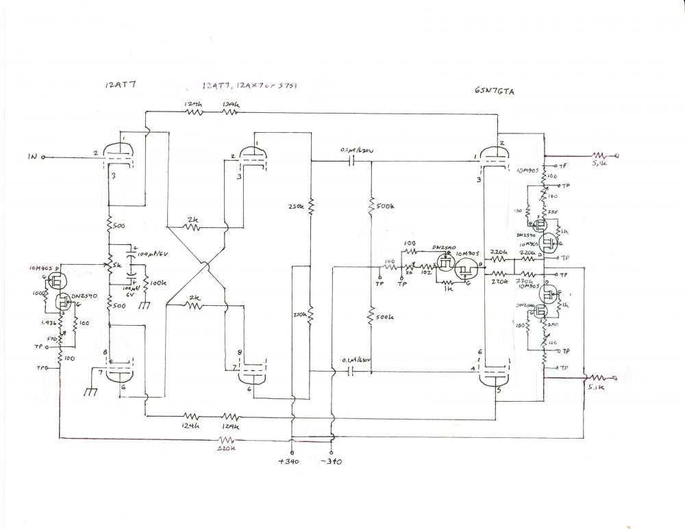
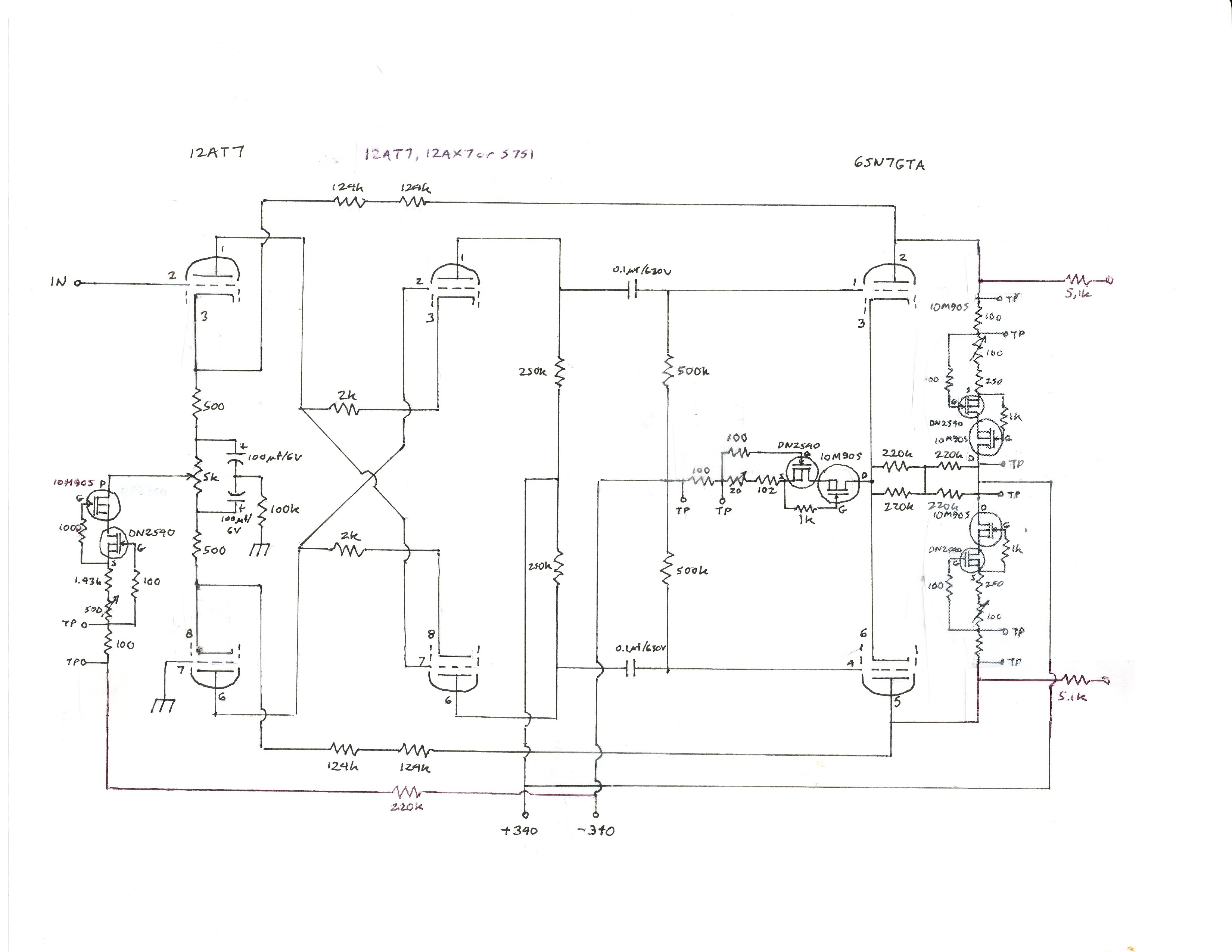
1 pointA couple weeks ago one of the 12AT7s in my SRX Plus failed, and in troubleshooting it eventually took out both input sections. On analyzing the failure it appears that I may have been just a bit too much of a cheapskate. Therefore I have slightly revised the circuit so that at least a failure won’t take out both channels, and hopefully won’t even take out one. The revision is pretty straightforward. Rather than supplying both input current source tails with a single resistor from B-, I substituted a 220k/500V rated resistor (270k/500V if you are using the original 300k plate resistors) from the B- rail to the input tail current source of each channel (which was previously marked on the schematic as being connected to -20v). The revised schematic is shown (ignore the +/-340 volt numbers, they should be +/-325 v). This resistor takes the place of the 10k and100k resistor chain in the shunt power supply that ran from B- to -C. This means that C- in my original power supply is no longer connected to anything, and the only connections between the high voltage power supply and amp boards are B+, B- and ground. For those using my shunt regulated current supply, you have to make a couple changes on the amp board. First, you have to cut the connection between the -20 volt terminal and one of the 100 ohm sense resistors, and then you have to cut the connection between that 100 ohm resistor and the other 100 ohm sense resistor. Then you have to connect each of those two sense resistors to a 220k resistor, which then runs to the B- rail – probably the closest place to do this on the amp board is the connecting point for the 100 ohm sense resistors on the output tail current sources – a bit of a kludge but it will work. In addition, I substituted a 10M90S in place of the upper DN2540 on the input current source. This modestly improves its performance, but more importantly should prevent the input current source from failing due to overvoltage. This modification does not need to be done for those of you who built the SRX Plus circuit using a Gilmore regulated PS, as that supplies the -15 volts that can be used for the input current sources.
 1 point
 -
1 point1 pointQuotes from http://physicsworld.com/cws/article/news/2013/jan/31/human-hearing-is-highly-nonlinear , originally published in Phys. Rev. Lett. 110, 044301 – Published 23 January 2013. "The information available from Fourier analysis is bound by an uncertainty relation called the Gabor limit. This says that you cannot know the timing of a sound and its frequency – or pitch – beyond a certain degree of accuracy. The more accurate the measurement of the timing of a sound, the less accurate the measurement of its pitch and vice versa." "Oppenheim and Magnasco discovered that the accuracy with which the volunteers determined pitch and timing simultaneously was usually much better, on average, than the Gabor limit. In one case, subjects beat the Gabor limit for the product of frequency and time uncertainty by a factor of 50, clearly implying their brains were using a nonlinear algorithm." In other words, conventional analysis of non-linear distortions in an audio system tell you absolutely nothing about how it sounds, because human hearing beats measurement by a healthy margin.1 point1 point1 point













Important Information
By using this site, you agree to our Terms of Use.