

Leaderboard
-
naamanf
High Rollers14Points6660Posts -
Voltron
High Rollers7Points34514Posts -
blessingx
High Rollers6Points17613Posts -
Augsburger
High Rollers5Points13165Posts


Popular Content
Showing content with the highest reputation on 06/14/21 in all areas
-
8 points
-
5 pointsLooking like it’s coming together nicely, Al. M&O will be making wood chips before you know it. I’m still ping ponging away.
 5 points
 -
Sourcing of currently manufactured semiconductors, even from OnSemi and other mainstream manufacturers, is log-jammed. This is a result of the perfect storm of Covid causing lines to be mothballed and then restarted and qualified, supply of the raft of chemicals needed, and similar problems Covid issues in the global distribution chain. Even vanilla parts are now out at end 21 early 22 delivery. And if you are going to build a PC - forget it. Processor chips have dried up as bulk users have stocked up (PC and automotive manufacturers mainly, but also smart phones and TVs). If you can buy one expect five times or more the nominal price. And pre-covid, particularly ceramic surface mount parts were on insane lead times, now even more insane. It will get better. From the end of this year onward supply ought to improve.3 points
-
3 points
-
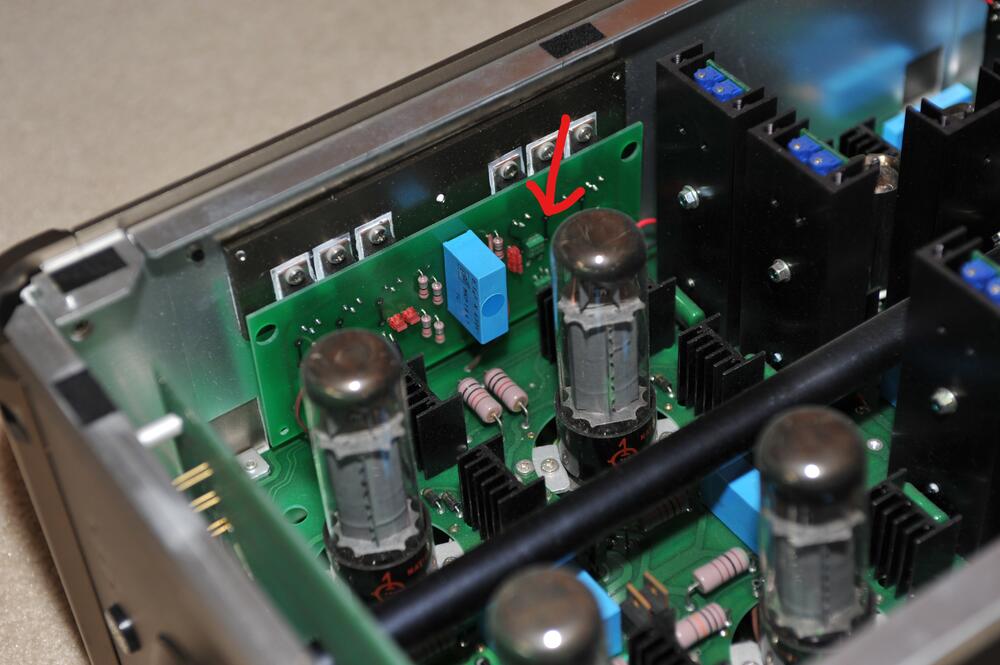
2 pointsIsn’t 2SA1413 a smd TO-252 something? Looking at picture below it seems Stax used something like that in the output current sources in SRM-T2. You might consider KSA1156 for 2SA1486 on heat sink and in batteries. Reduce high voltages to +/-400V and you can use KSA1156 in the output current sources as well. As I see it reducing the voltage is beneficial without drawbacks. I’ve used STN9360 in batteries and even in output current sources. Bend outer pads slightly outwards to fit holes and solder them in standing. In current sources they will idle at 1/4W.
 2 points
 -
1 point
-
1 pointI had a fairly good experience with Vesper, they obliged my request to replicate my Mk1 pads' dimensions fairly closely. Whether those two pads sound the same or not is something I'm going to properly test once I get a pair of in-ear mics... in terms of comfort they beat my Mk1 pads by actually sealing on my head though! I think my head is not the right size for my Mk1 😅1 point
-
1 pointuse 1156 on the heatsinks, 1486 (if you have them) everywhere else.1 point
-
1 pointNo. The CCS has the potential to exceed the -400V rating of the 1156. Bad things could happen if it does. The batteries might be possible though I don't recommend it. It's cutting it close if something goes wrong or while you are doing the initial adjustment on the batteries. I'm pretty sure Q1, Q2, Q3, Q28 & Q29 are on the heat sinks. I'm confused by your statement above.1 point
-
1 pointBack in the day (for various builds) we used 2SA1156 (-400V) and 2SA1486 (-600V) pretty interchangeably provided the voltages were in spec. K2SA1156 is a direct replacement for 2SA1156. I would recommend using K2SA1156 where it works. It is proven and better not to jury-rig something if not needed.1 point
-
1 pointAt full voltages you can use K2SA1156 (as JoMat suggested) for Q1, Q2, Q3, Q28 & Q29. It's what I've been using in my builds and is a good substitution. I also use STN9360 as a replacement in some areas, but I've redesigned the boards specifically for them. I don't recall which of the remaining 2SA1486 (batteries & CCS) are mounted on the heat sinks, but if they aren't, it seems like you could use 2SA1413 though I never have.1 point
-
1 point
-
Yes, this is reliable vendor. I am from India and have used them for DIY many times.1 point
-
1 point
-
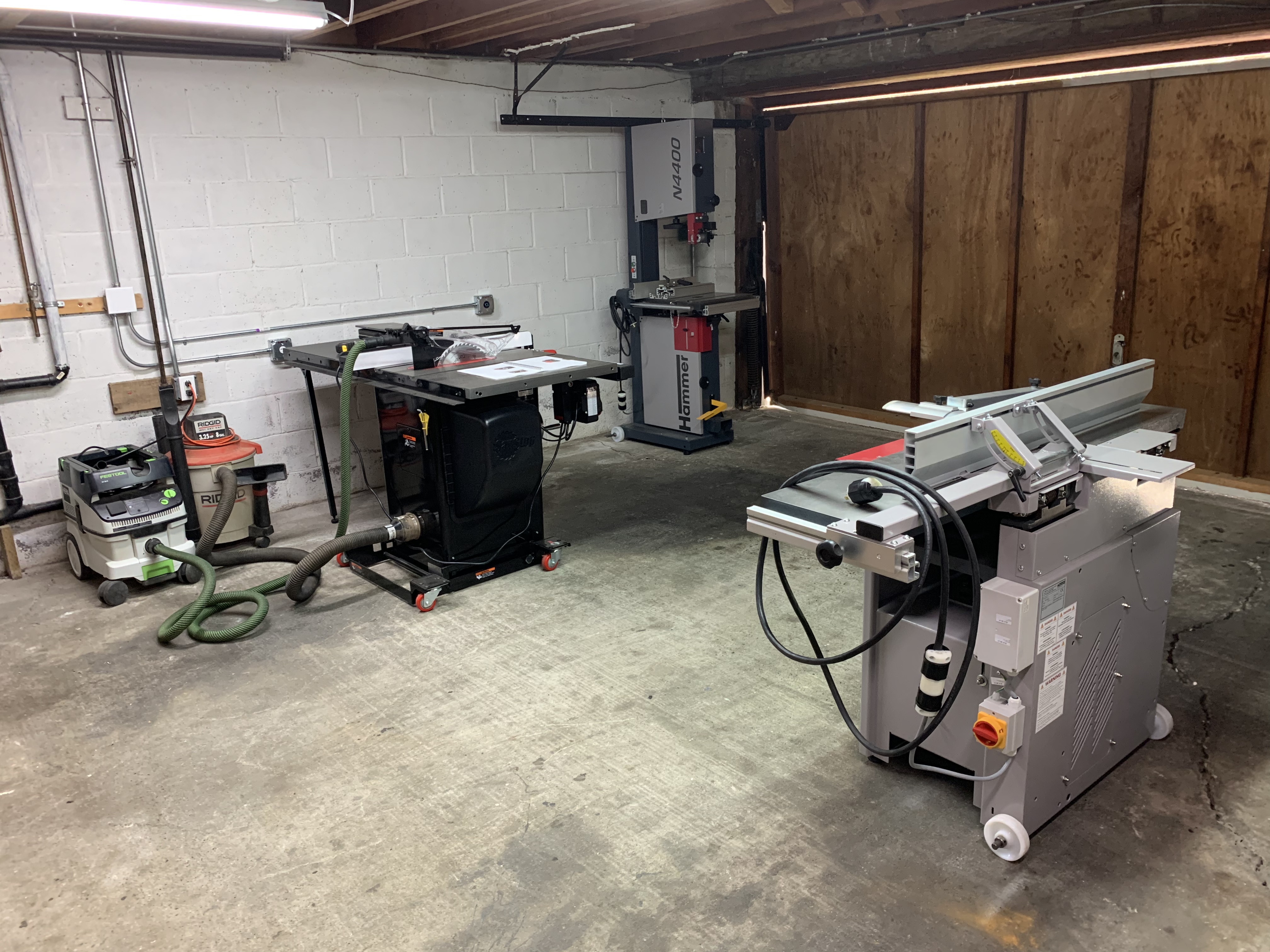
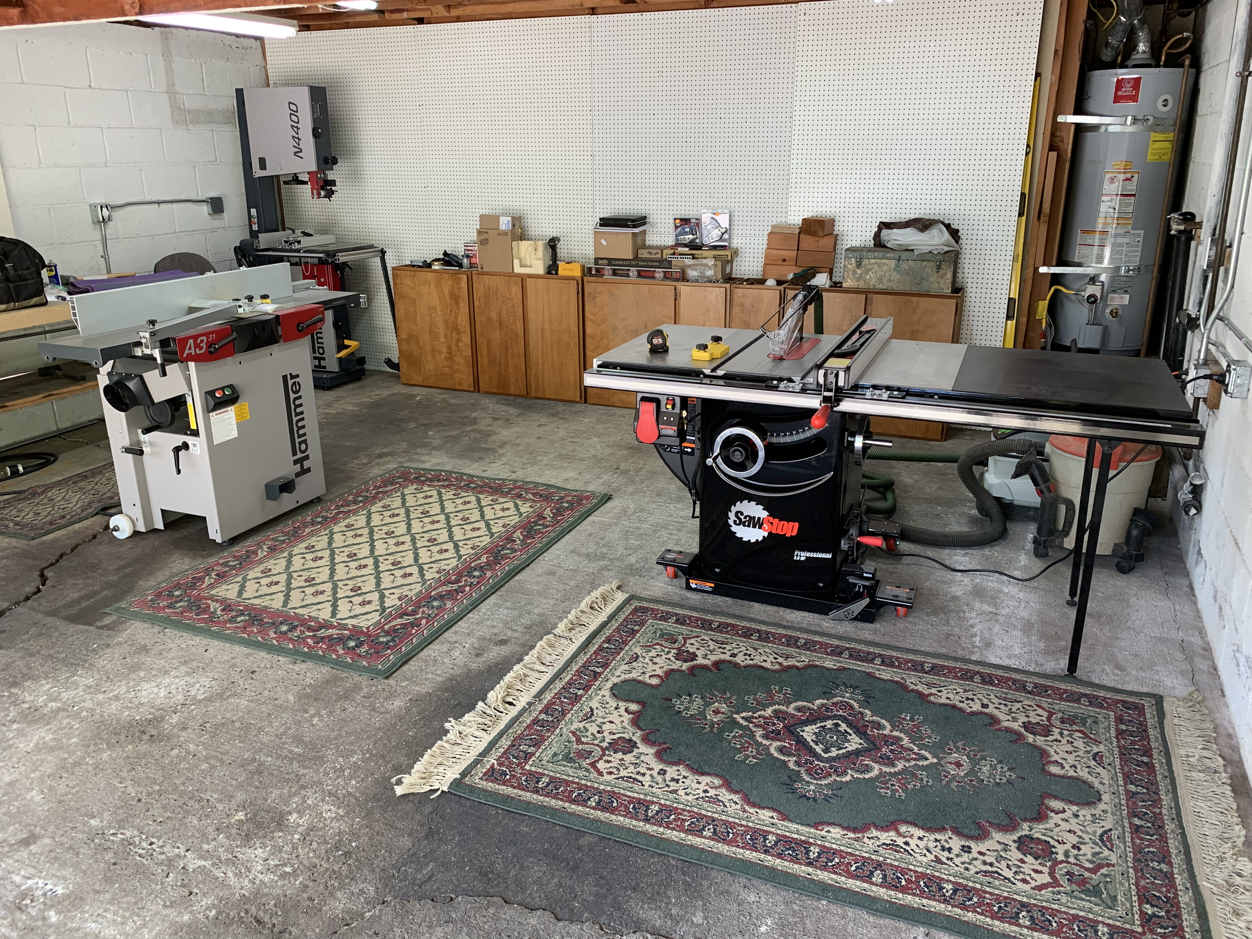
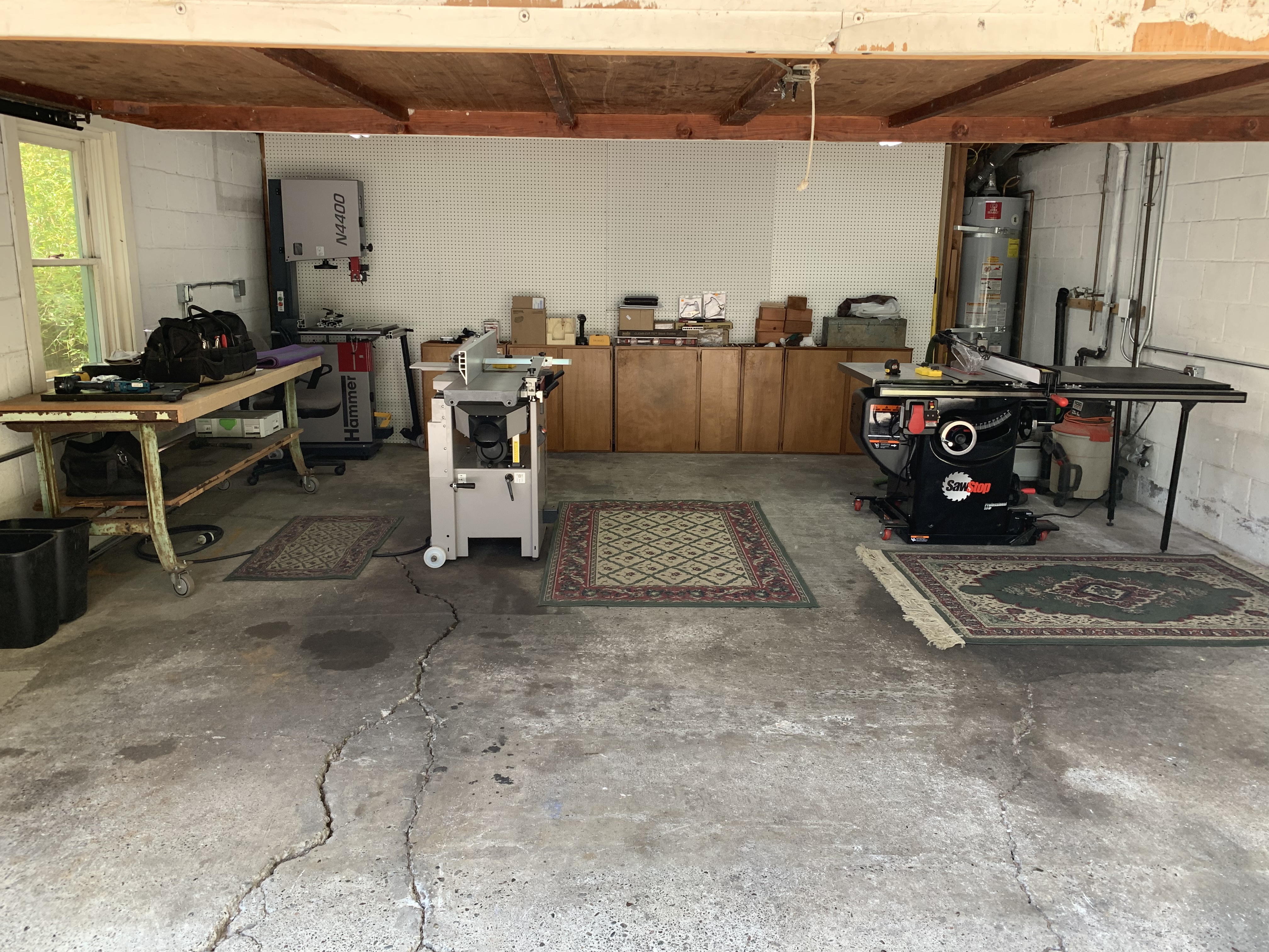
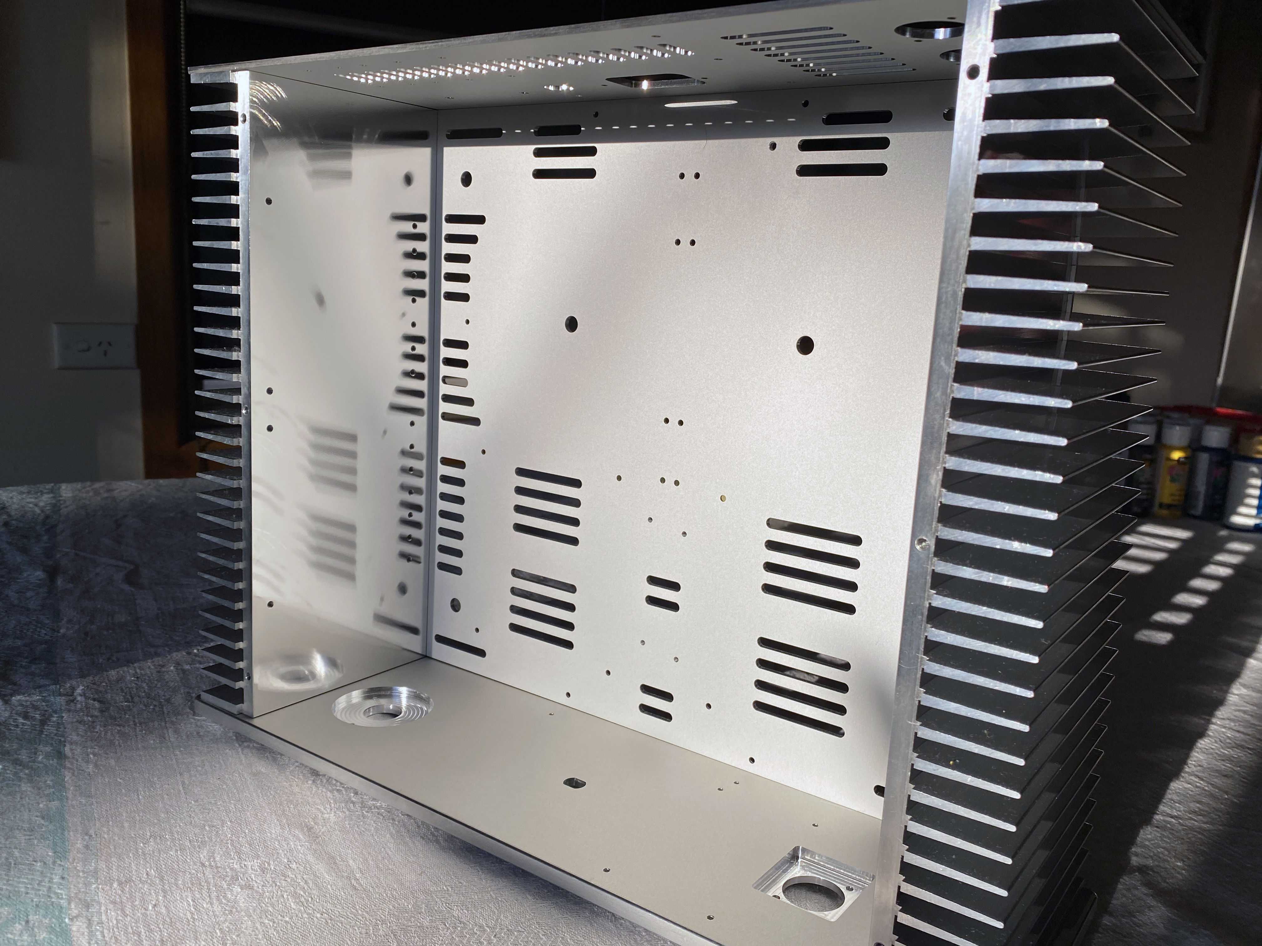
1 pointThe new shop is mostly wired and the big tools all have dedicated 240V circuits. I cleaned up and tried moving some things around to see how the space will work. It feels spacious compared to where we have been working in a chopped up basement space. This is approximately where the table saw, bandsaw and jointer/planer will reside, although the bandsaw will come away from the wall and may change orientation when in use. The blades for the Hammer bandsaw are still being made so it is going to sit in a corner for now, and the garbage rugs used by the tenant for years are now in place for some comfort and grease spot coverage. It's taking a while to get set up but I'm trying to be patient and get things done right. I'm going to enjoy working in this space and it will be much easier when Milo and Otis are in the shop together.


 1 point
 -
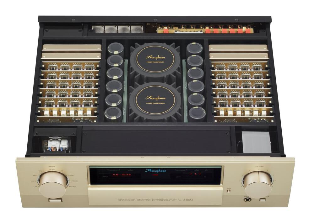
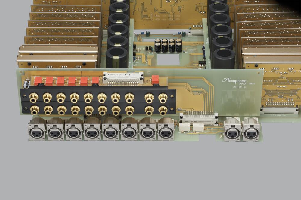
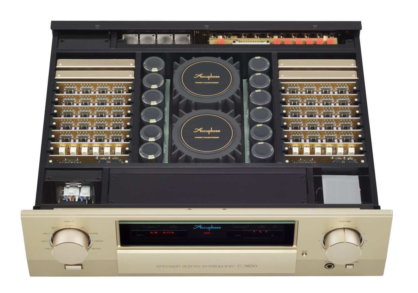
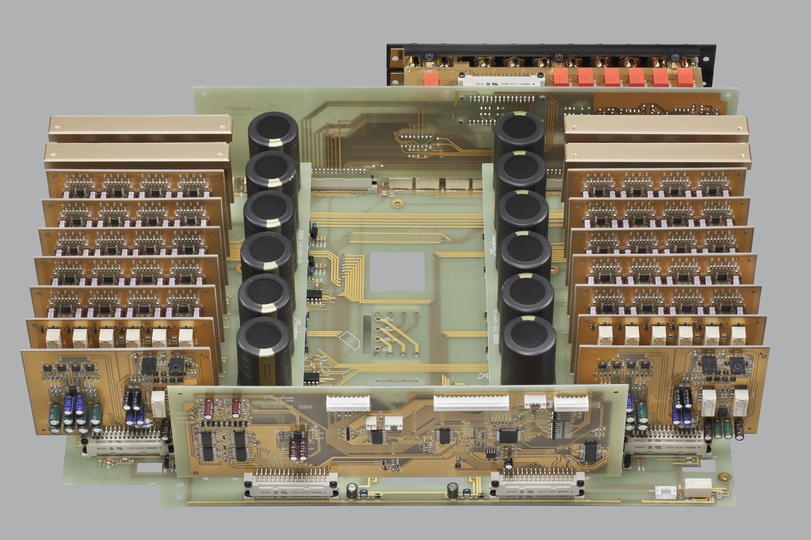
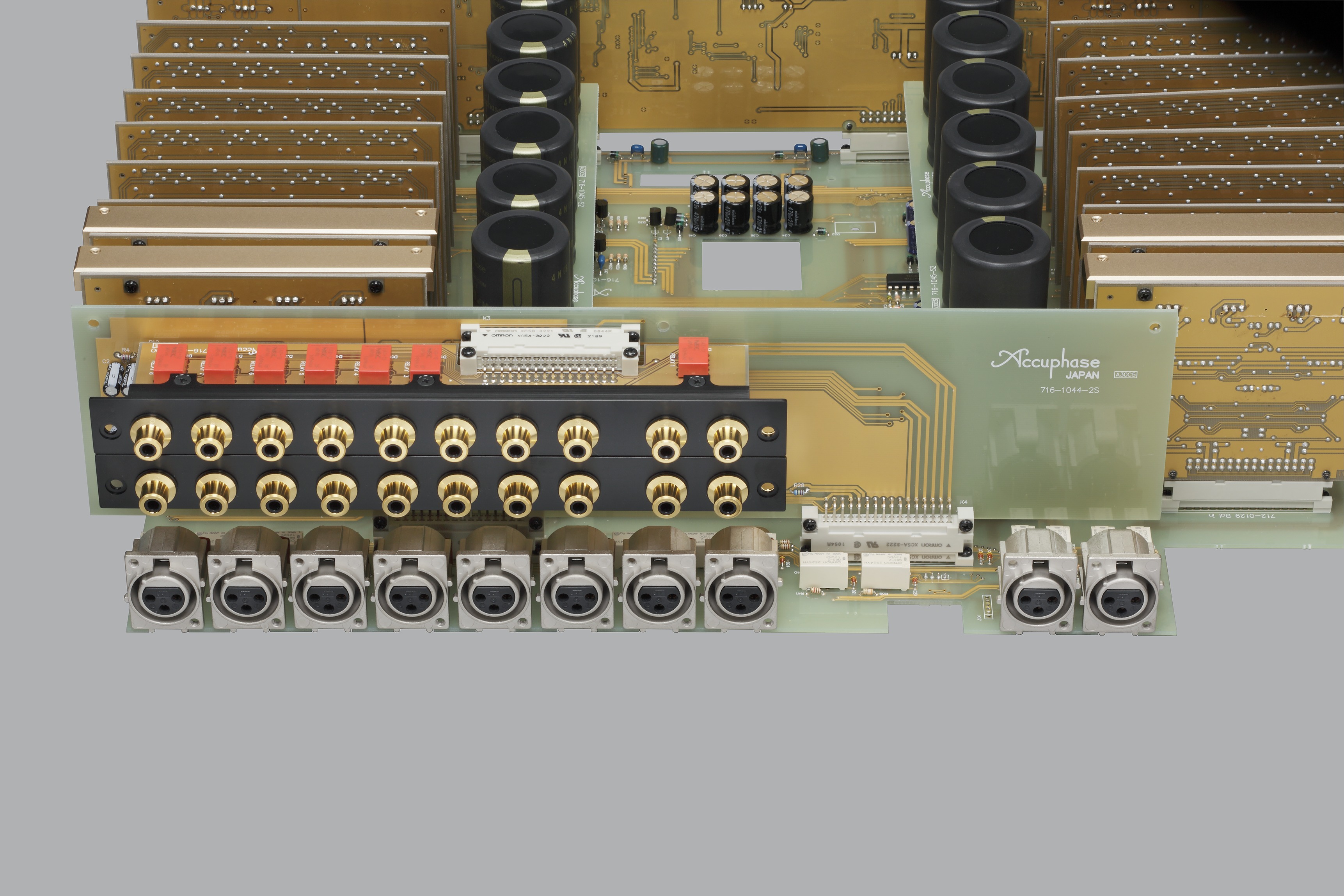
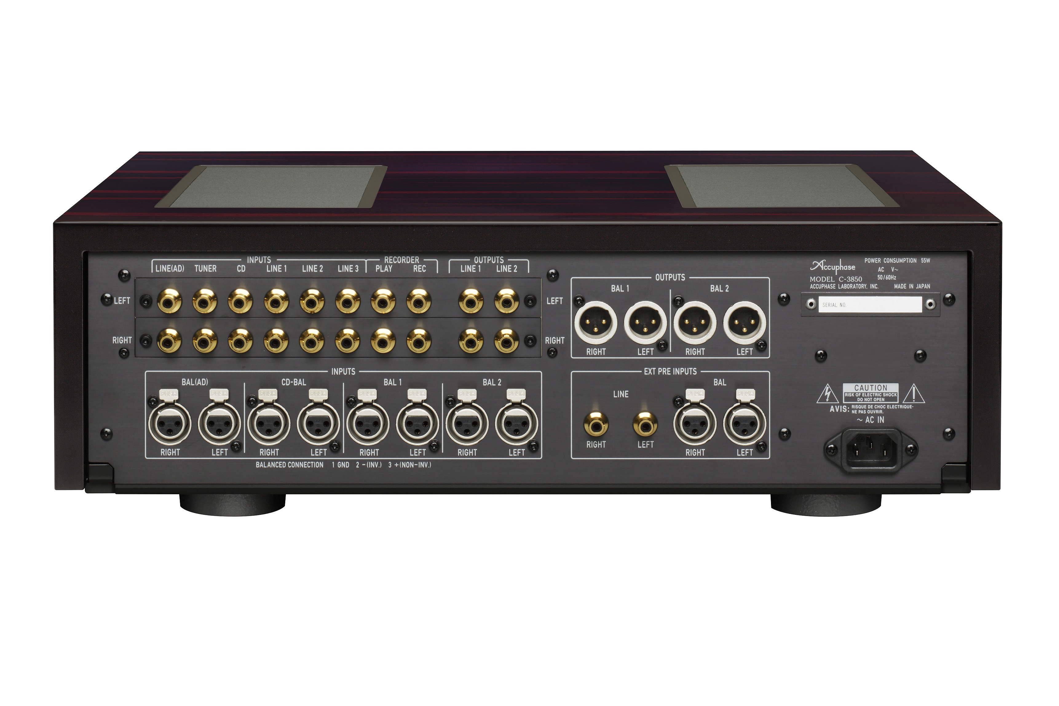
1 pointAccuphase C3250 Here the used Omron PCB connectors XC5A-3222 and family. Very nicely done.

 1 point
 -
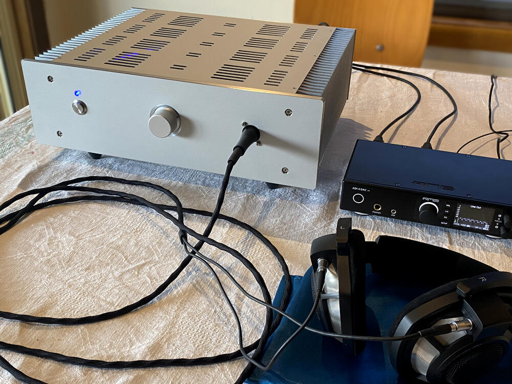
A CFA2 balanced. Finished this a whiles back.
 1 point
 -
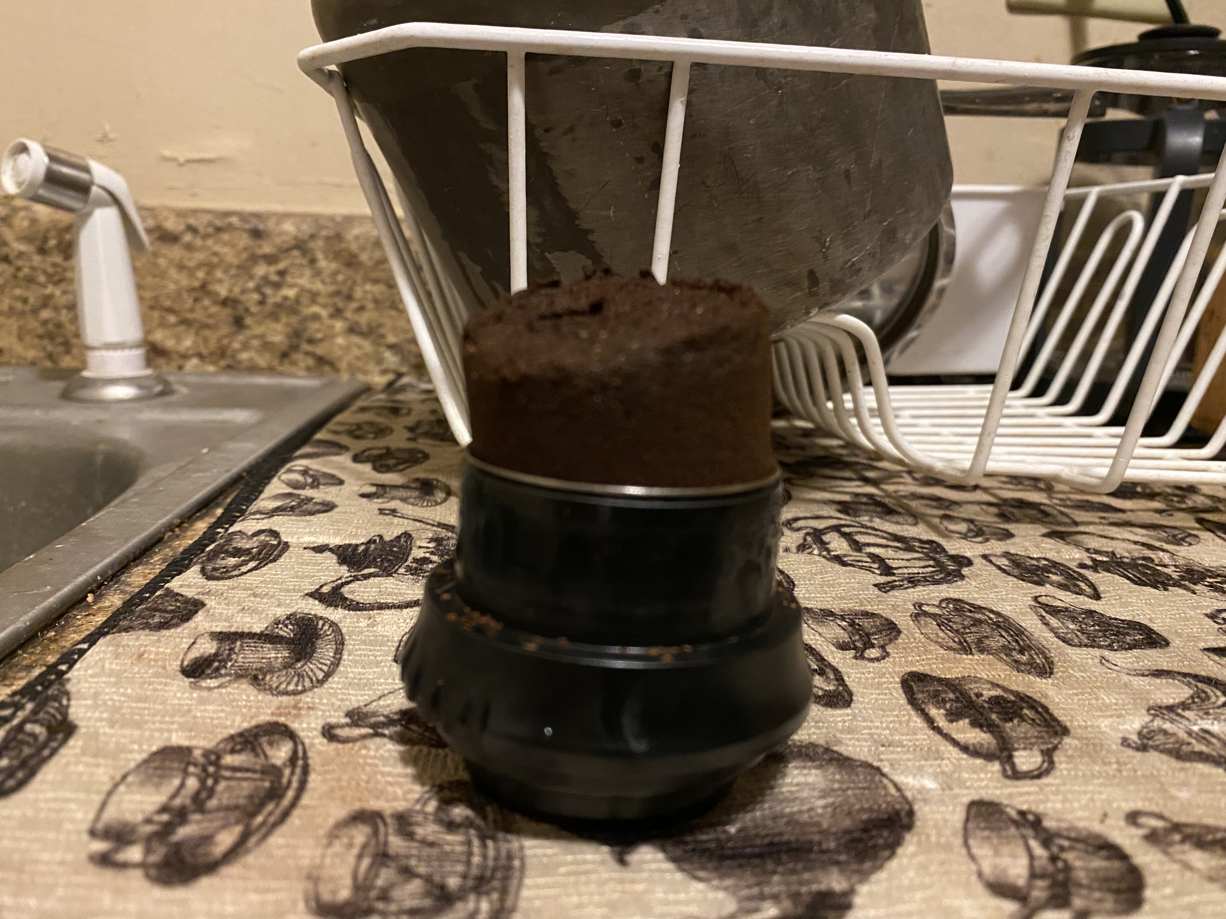
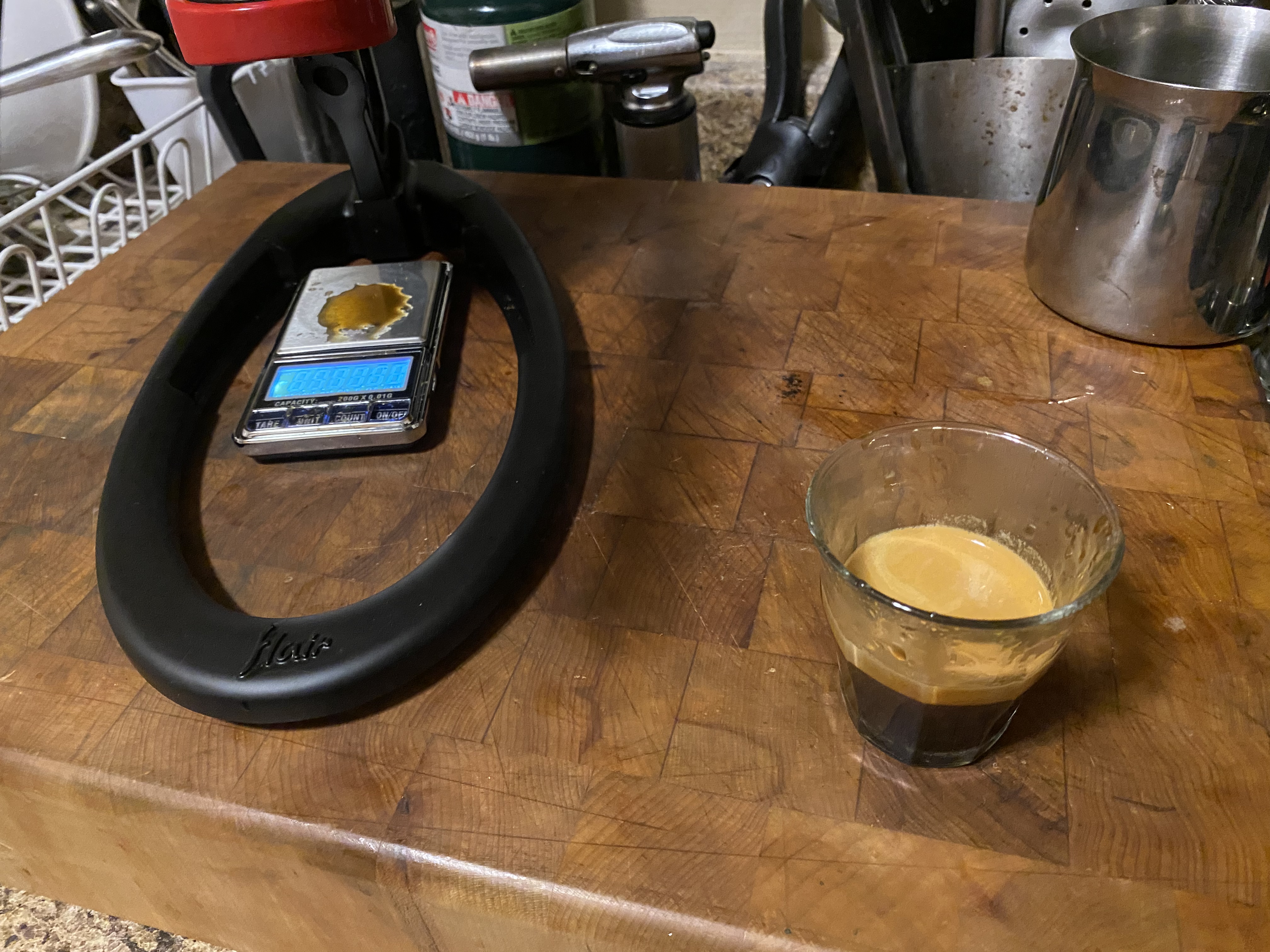
I think I have my Flair dialed in. The pressure gauge is a must have. This was a delicious shot made with light roast yirgacheffe, just from a grocery store, and ground just with a Bodum Bistro (you can get away with more with a manual machine, since you have complete control). It’s a pain in the ass to make coffee this way (and I use a NanoFoamer for milk), but I rarely drink coffee, and I love the Flair. I like that it’s a pain in the ass. 16/32 in 31 seconds, not quite 9 bar. Sweet, complex, moderate acidity, good texture. You couldn’t ask for a more perfect puck or a prettier shot (not that crema adds anything useful).

 1 point
 -
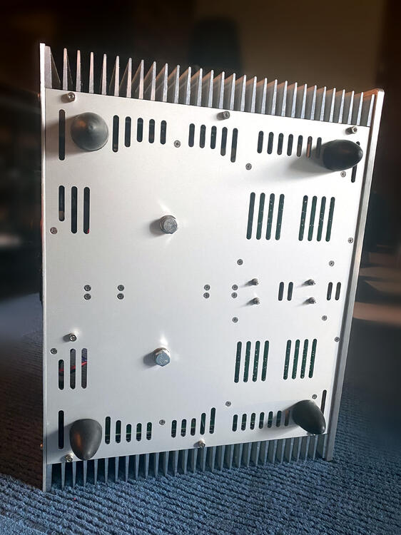
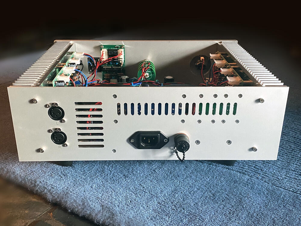
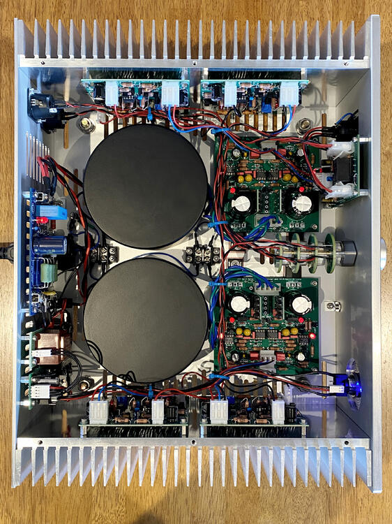
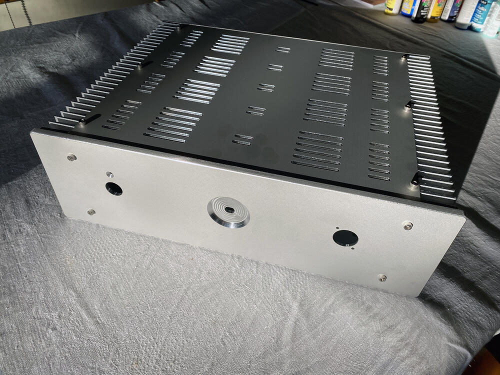
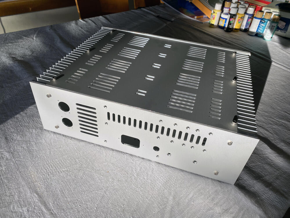
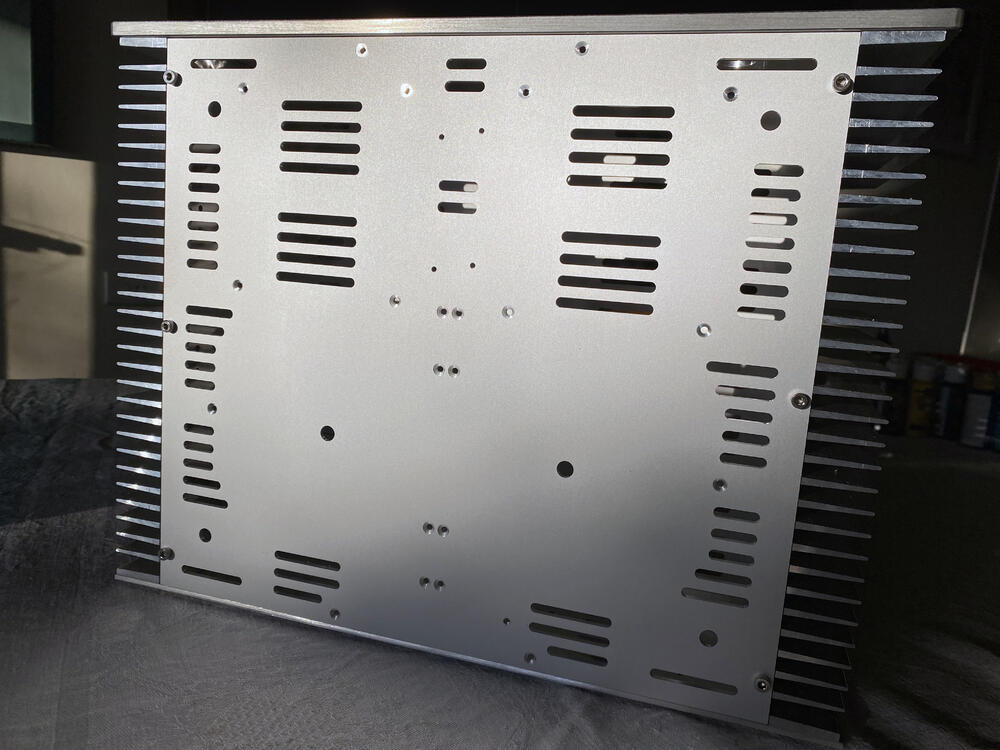
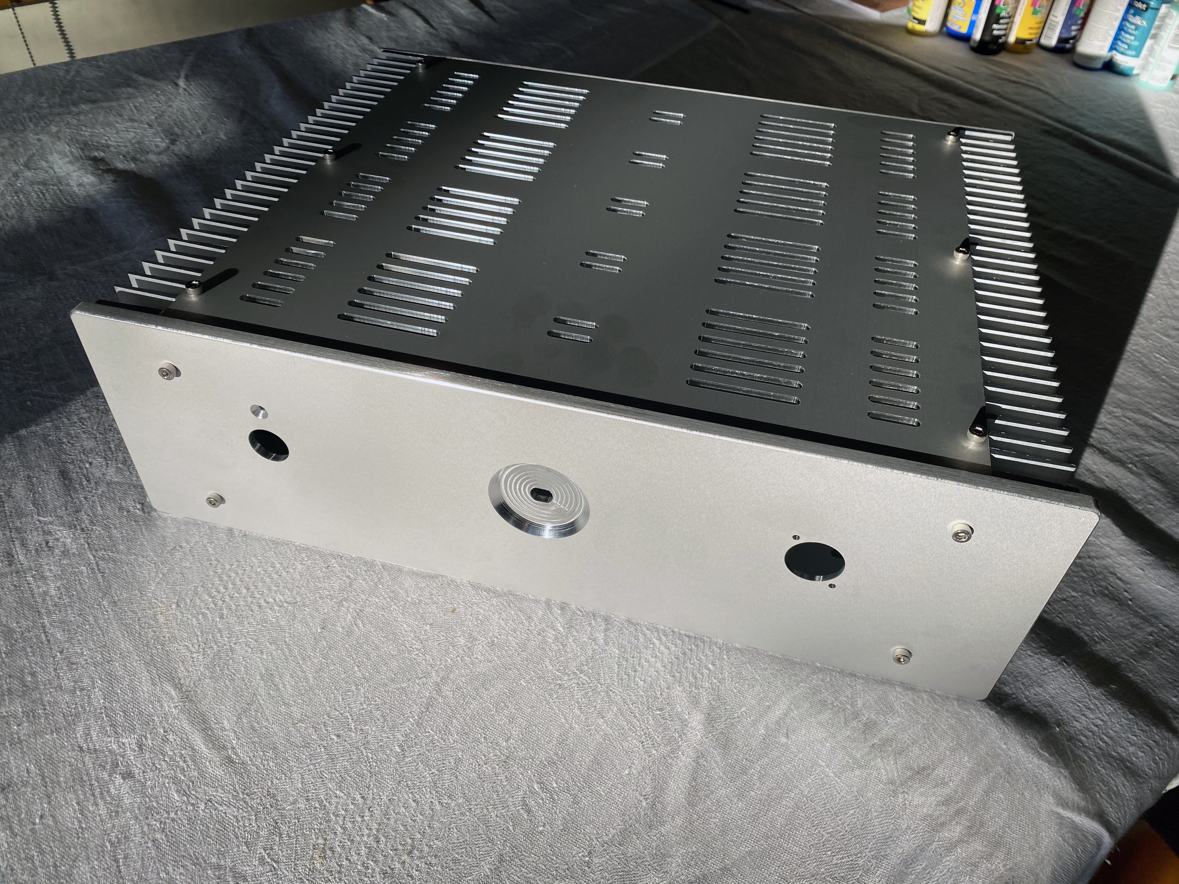
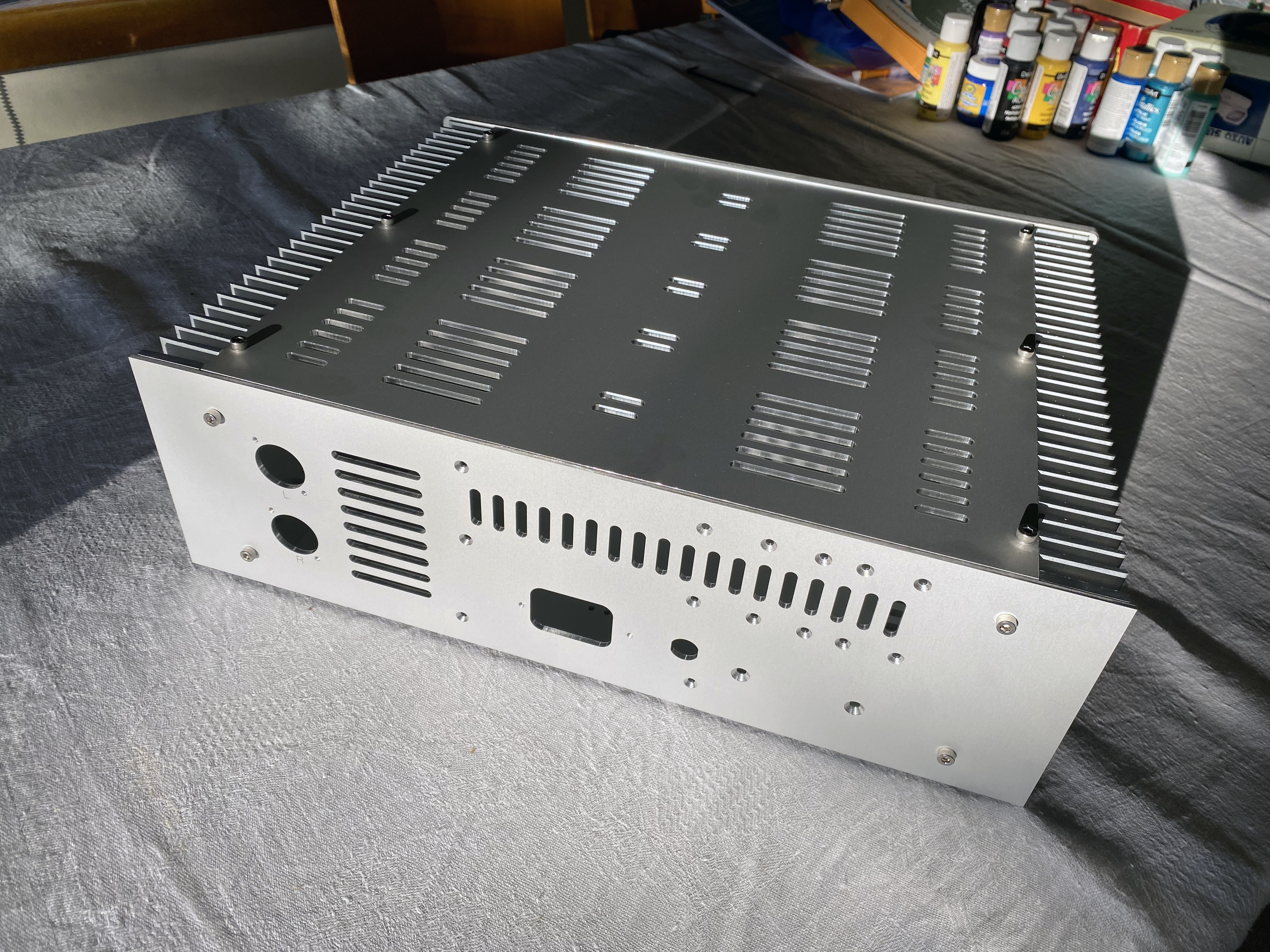
1 pointLong time between drinks, been working on this for a few months and finally got my panels back. It’s going to be a dual mono GRLV PS with a quartet of CFA2’s, balanced in and out using a Goldpoint 10k 47 position stepper.
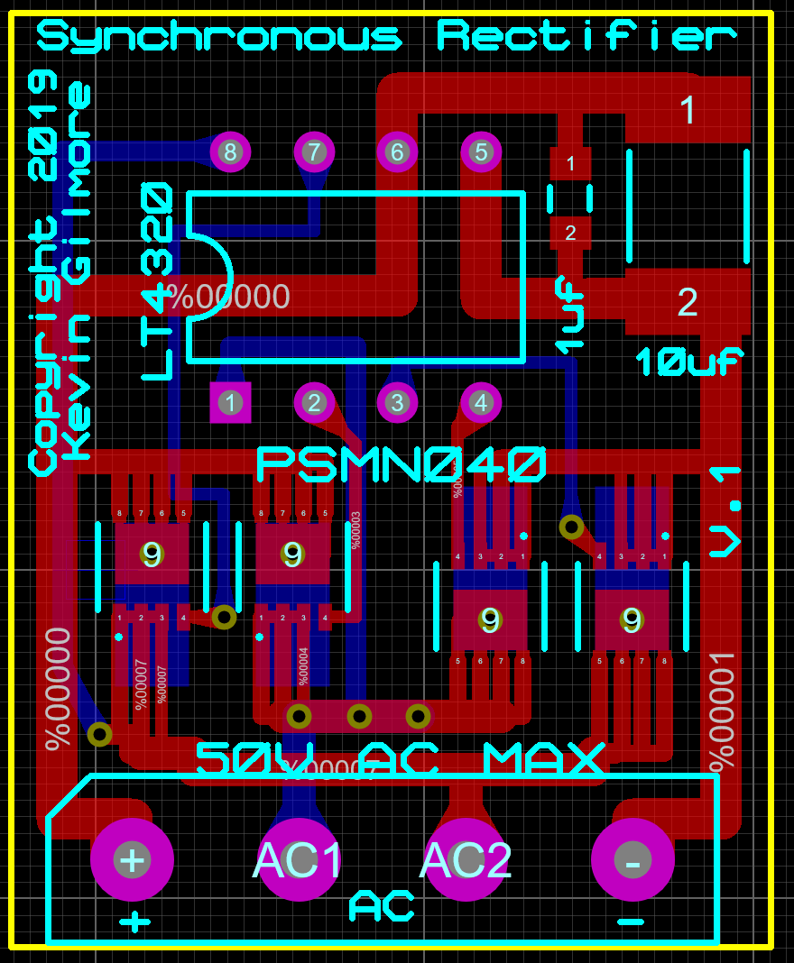
 1 point1 pointKevin, I have just built 3 of the synchronous rectifiers, I built a little test setup with just the + side of a spare golden reference LV board and used a single non centre tap AC ionput. (LV board set to +14VDC output transformer known good). I found all 3 rectifiers to produce rectified output with some 100hz ripple by scoping the + terminal output of the synch rec and the scope ground on the ground of the LV board. Testing drawing from 0mA to 300mA using a DC electronic load from the LV board produced a stable, non drifting clean output - I expected 14V and got 14.014V. The output voltage dropped by about 3mV when comparing the 0mA draw to 300mA which seems reasonable. My conclusion was the sync rec boards where correctly soldered and working. I then desoldered the traditional bridge rect from my well tested and fully working blue hawaii gold ref LV board (which uses a centre tap transformer for it AC input) I replaced the bridge with the synch rec, brought the amp up slowly on a variac and immediately noticed a buzzing sound coming from the golden ref board and only the + side of the board got to 15V and stable with both leds lit and the neg side could not get past about -10V and the second led did not light on the neg side... this was with the gold ref lv connected to the blue hawaii amp boards and drawing current but before the delay circuit activated the B+ lines. I immediately pulled the power before the B+ came up to protect the amp. I repeated the experiment with no load i.e. the blue hawaii not connected to the gold ref LV and still got the same behaviour. I tried all 3 sync rec and got the same result. Thinking I had damaged the LV board I put back the original bridge rect and both the - and +15V both were fine and measured exactly as before I removed the original rect. regards James Update, Looking at the diy forum, https://www.diyaudio.com/forums/group-buys/333844-ideal-bridge-rectifier-gb-23.htmll they also say the LT4320 will not work correctly on a centre tapped transformer.... the two AC outputs of the transformer must be in phase with each other and most centre tapped transformers are out of phase... I have successfully got the synch rectifier working with the golden reference LV power supply. but only using transformers that have dual secondary windings. I cant not get centre tapped to work correctly. Update I am convinced the synchronous rectifiers only work with non centre tapped transformers.1 pointsomeone needs to check this, works as single rectifier with center tapped transformer, or a pair with dual secondaries. Up to 72vdc, perfect for GRLV caps are 100v rated, 1uf is 0805 size, 10uf is 2220 size I can certainly do a bigger version with different fets for higher currents and lower voltages. .9 x 1.1 inches syncrectifier.zip
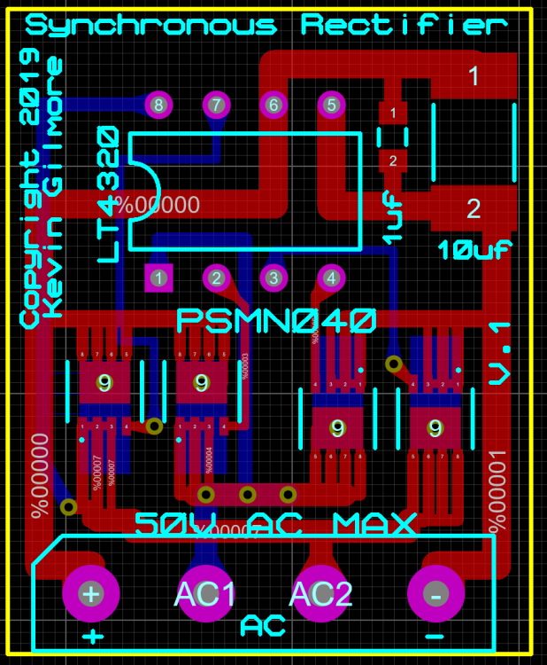 1 pointhttp://imgur.com/xKQhzZZ Take from Pars's pic,Change those 1.5K resistor,top and bottom ones are R8,R9 for V+: (R8 + R7) / R7 x 10 (reference voltage of D5 - LT1021-10) for V-: (R9 + R10) / R10 x 10 (reference voltage of D7 - LT1021-10) For 15V you can go 750R,1.5K Set others you may need to change different voltage version of LT1021 don't need to change caps and OPAs for voltages you mentioned ,but you may need to change zenzer value to voltage/21 pointwhat voltage do you want? I do not understand Kevin's method so came up with this: desired voltage x 150 -1500 = R8, R9 40v is 40 x150=6000 -1500=4500 30v is 3kR 25v is 2250R1 point


Important Information
By using this site, you agree to our Terms of Use.