

Leaderboard
-
Voltron
High Rollers15Points34514Posts -
kevin gilmore
High Rollers8Points7204Posts -
mwl168
High Rollers7Points1379Posts -
Craig Sawyers
High Rollers6Points5495Posts


Popular Content
Showing content with the highest reputation on 11/12/17 in all areas
-
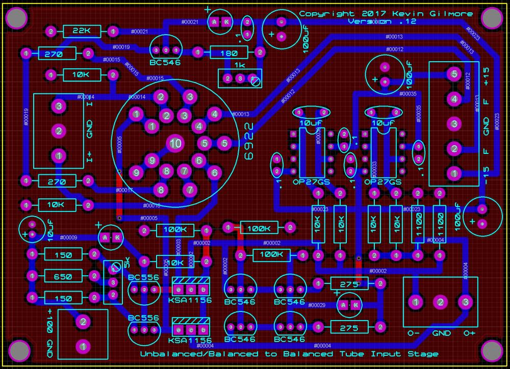
So I've been looking at a bunch of tube/solid state hybrid dynamic amp schematics, and every one of them is some form of bad, or really bad. (one person/ex company in particular) Low voltage plate, capacitve coupling of a high impedance source into a low impedance, poor balance etc. There had to be a better way. true balanced input. dc coupling. low impedance output. no feedback. proper use of a tube (pure transconducance) etc so I came up with this, work in progress. 4 x 3 inches ubaltobaltubeschem.PDF
 6 points
 -
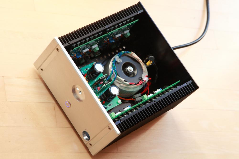
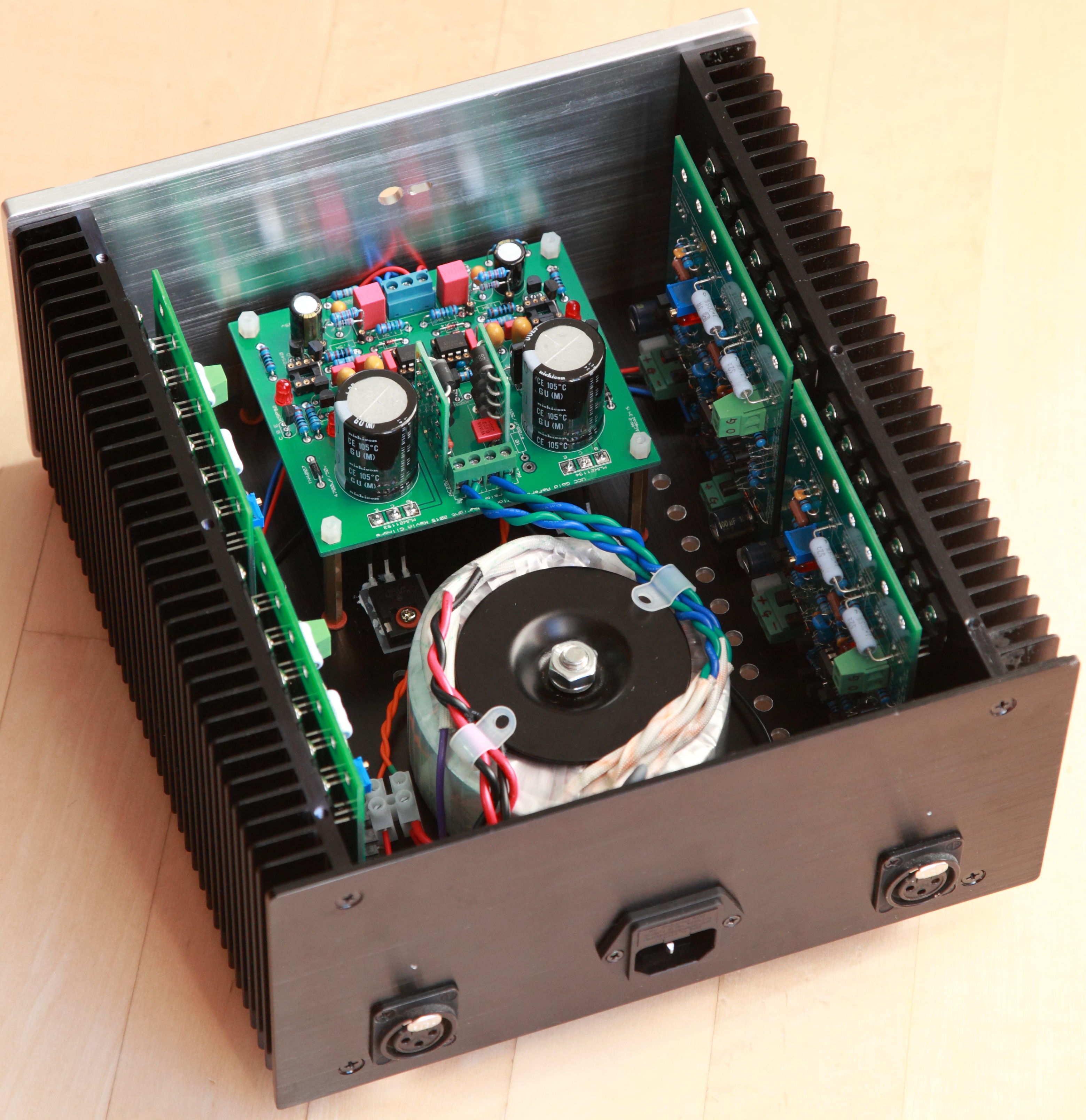
Close to finish casing my balanced CFP amp. Waiting for a 4-pin XLR socket. This one runs on 26VDC rails and 220mA bias current. I am posting an unfinished amp because I want to report that I tried OPA551 for the servo OP and it appears to work fine at less than half the cost of OPA445 but only good to 30VDC. something to consider for those that may be in the process of sourcing parts for their builds. The bias current proves tricky to dial in. It drifts downwards as the amp warms up and seem to continue to go lower even after a hour of operation. The range of drifting is significant too. I am observing 70mA and possibly higher.

 5 points
 -
4 points
-
4 points
-
2 points
-
2 pointsFunny that.... I have owned a pair of these, and know of others who own them, and have never heard from any of them with problems with the HD280 pro. I have read on different forums that they were fragile and sounded like cardboard, but have also heard of many other headphones which were destroyed by neanderthal owners. How many HD600/HD650 headphones had their headbands broken? What about the SR-007 with a ding in the cup. It seems that the cheaper 'phones are treated like dirt whereas the more expensive are likely to be more mollycoddled. Since you used to be able to buy a HD280 pro for much less than $100 it certainly lends to them to be abused and neglected as well being employed as toys for your recalcitrant pets and feral kids.....2 points
-
2 points
-
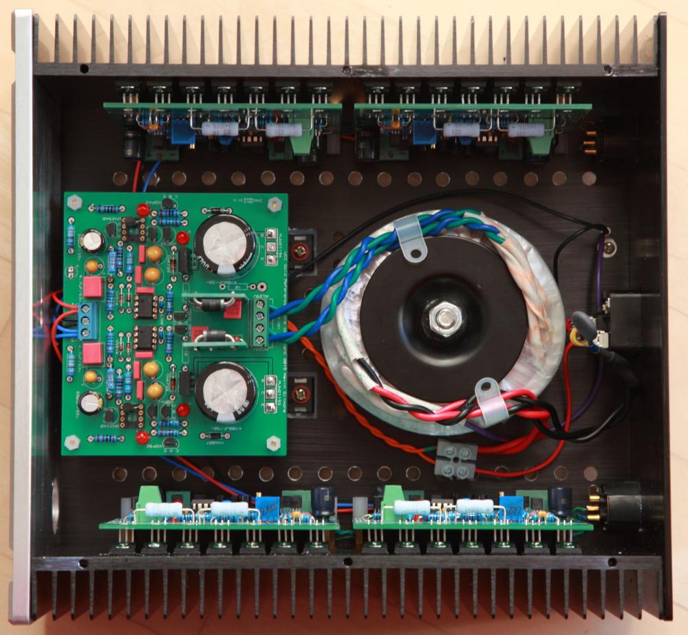
Thanks! The bias current drifts at 22VDC rails sitting in open air as well. I do think that it drifts more with higher supply rails and with all the guts in the chassis (re: higher running temperature). By the way, although this chassis makes for a compact and neat build, I would suggest using a larger chassis unless you like your amp to run rather warm. The heatsinks for the amp boards are adequate (45 C after 5 hours) but I think the pass transistors of the GRLV are putting out lots of heat - case temperature is about 55 C bolted to the bottom plate. It probably has to do with my stupidity - I am using a 28vac trafo so the pass transistors have to drop 12VDC and provide over 1A current. I should probably have opted for a trafo with 24 vac secondaries. (EDIT: I should mention that the Antek AS1228 secondaries (28 vac) sag to about 26.5 vac with this heavy load and with that input the GRLV could not sustain regulation for 28VDC rails as I originally planned. I am not certain how high a regulated output a 24 vac trafo can provide.) This amp rekindles my love for the LCD 2. Thanks Kevin for yet another great amp that seems curiously overlooked by many. And thanks to congo5 for leading me to it and all the help and advices through my build.1 point
-
1 pointJust catching up, congratulations to Jacob, Steve, and Al (on the neighbor). As always, all my jealousy to Stretch.1 point
-
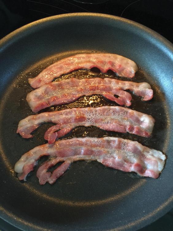
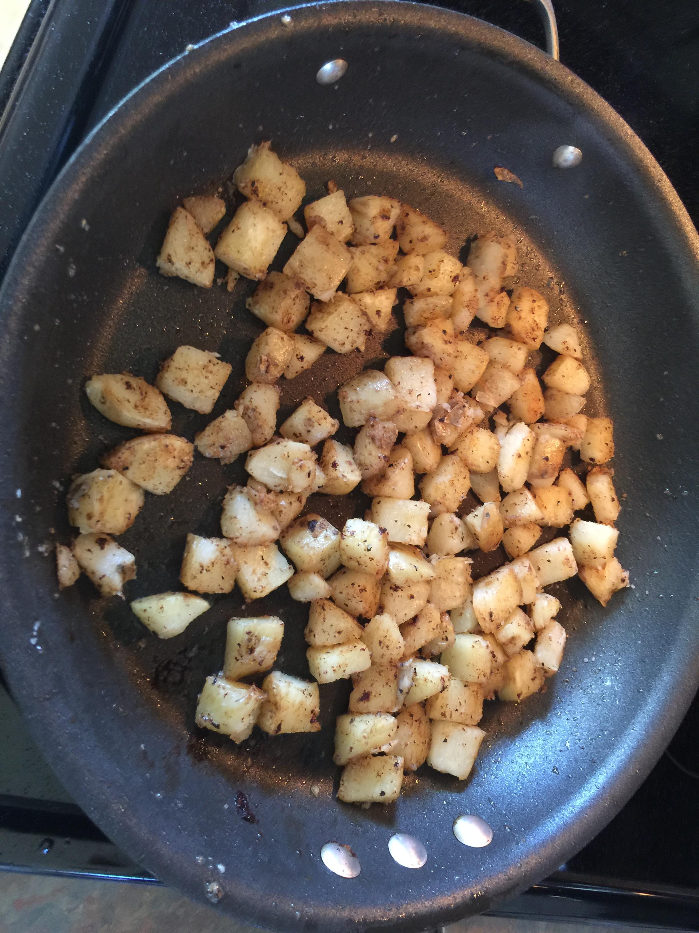
1 point1 pointFirst did some cooking, then eating. Step 1: Fry bacon. Step 2: Make home fries in bacon fat. Step 3: Combine with eggs. Top with cheese, eat.


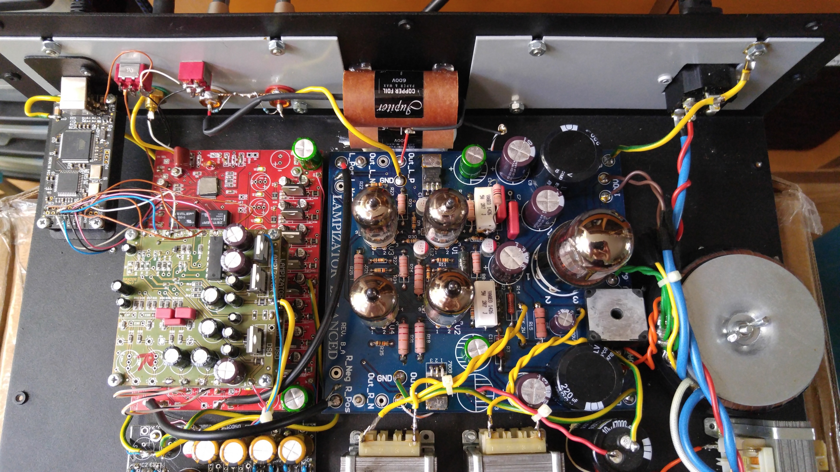
 1 point1 point1 pointFrom long-term memory: the 280 is that lovely combo of hot treble and boomy bass that makes everything sound like a wood screw to the eardrums. I used it with a 2nd-gen iPod at the office (didn’t have fancy amps at the time), so it may improve with moar power (but I doubt it). It lived on my desk and I treated it well — the piece which snapped was the plastic extension on the inside of the headband next to the ear cup. It could not withstand the strain all headphones endure in that spot when you hold the cups apart while putting the unit on your head.1 point1 pointI’ve had my 650 for over 10 years and have never had a problem. On the other hand the headband 280 pro broke after a year and I treat everything I own with care. In addition, my head is much smaller than the average headphone wearer. Plus, they were so so uncomfortable whereas the 650 and 600 are one of the most comfortable pairs of headphones ever made in my opinion. Not to mention, the 280 pro sound like crap. So I completely agree with Dusty. I am actually somewhat interested in the DT1770 to use in the office. I would love to have a closed pair of headphones that sound decent, isolate, and are comfortable. The DT 770 are one of the most comfortable pair of headphones I ever owned and isolated like crazy but were way too dark/muddy sounding. So far, I have just heard people complain about the DT1770 being too bright which is probably a good sign.1 point1 pointNo...just no. Show me a picture of the inside of the "well done" boxes with "quality PCB's". Also explain how exactly the tube PSU is regulated and what the fuck that tube stage does with the R2R modules? I'm waiting... Ohhh and what quality components? Compare it to the 600$ Denafrips Ares... In short, this is garbage for gullible people who don't know any better. The classic audiophool who thinks "toobz" make shit better when in fact they have no role here let alone idiotic DHT tubes. How is that good for low level signals? Let's just post this gem... So...this is supposed to be high end but to me it looks just like a random PCB's sourced from China, shoddily crammed into a cheap chassis with some sucky ass tube output. It can't even meet CE specs so by definition, this is illegal for sale in the EU.
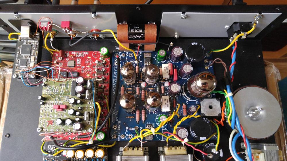 1 pointInterested in this. A HD650 with more sub-bass. https://www.stereo.net.au/news/sennheiser-announces-hd-660-s-headphones
 1 point1 pointA few more things, and I guess I missed taking a photo of the things from Friday..1 pointCheers team, I had a good birthday, many wishes, baked German breads most of the day, and hung out with Marin folks, was a treat being back in the area for my 50th. Thanks all...1 pointI dig that ^ Fratellis song. Have it on a favorite in some playlist...DEEZER I think. Anyhoo....for whatever reason it flashed me back to some vinyl I have from back in college HS1 point1 pointBuilt yet another GRLV for my CFP amp. This one set for 26VDC rails and the current draw from it is about 1.1A (for a balanced CFP amp with 220mA bias current). Empirical evidence that the GRLV can supply more than 1A current from both rails. Don't have LT1021 on hand so using LM4040 for voltage reference for now. It's much cheaper but also much higher noise. OP07 in place of OPA134. Those resistors standing tall and proud is my way of easily adjusting rail voltage while I am tinkering with the CFP amp. They are inserted into Mill-Max headers below. Cannot really see from the pic but the pass transistors are bolted to a heatsink below. EDIT: at this current draw, you need to allow for higher dropout voltage and heatsinking for the pass transistors. I would plan for solid 26vac input for 26VDC regulated rails to be safe.
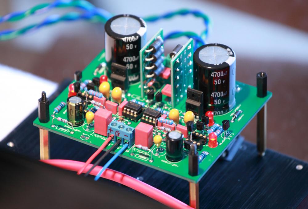 1 point1 pointI had a 280Pro about 12 years ago. Piece of junk. It’s brutally uncomfortable, painful everywhere it touches after 15min of use. It also causes listening fatigue within 30min if you can sit through the pain — probably hot treble, but I blocked it out of my mind. To add insult to injury, the cheap plastic where the cups connect to the headband will snap and break within the first month, as it can’t survive the strain of being put on and taken off the wearer’s head.1 point1 point1 pointYellow cherry tomatoes and fresh basil courtesy of Al's garden.
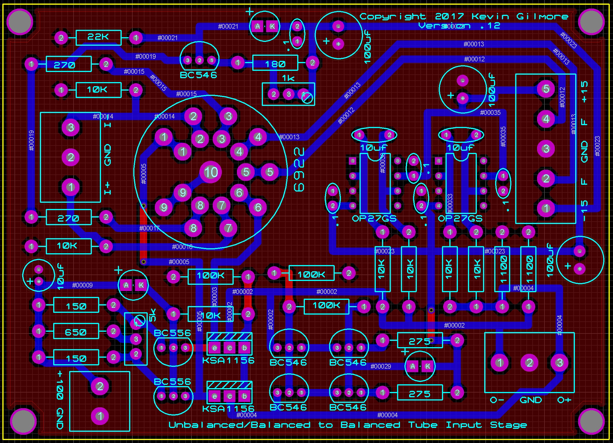
.thumb.jpg.d7419b4410ccfbdc5f3bb86f65910cbf.jpg) 1 pointwill this version also be for DIGITAL, Natural Sound?1 pointI don't need this. I like my HD600. I don't need this. I like my HD600. I don't need this. I like my HD600. I don't need this. I like my HD600. I don't need this. I like my HD600.1 point1 pointLet’s look at the input stage in more detail – I don’t feel too guilty about putting this here since this discussion is more detailed (and longer) than the AudioXpress article – word count limitations and all that. As originally designed by Stax, it is a long-tailed cross-coupled cascode phase inverter with the right tube grid grounded. This can easily be converted to a balanced differential stage by un-grounding the right tube grid and using it for the negative input of a balanced signal. Unfortunately, if we put a signal into the left tube gird with the right tube grid grounded, we don’t get a completely balanced signal coming out. There are a number of things that can be done to improve the output balance. First, the higher the gain of the section, the closer we can get to a balanced output. A cascode has a high gain, so that helps. Second, the cross-coupling between the plate of the lower tube and the grid of the upper tube improves the balance, as explained by D.R. Birt. He describes it in an article in the June 1960 issue of Wireless World. He notes that this cross-coupling does not alter the overall gain of the cascode, thus for purposes of calculating the gain, one can neglect the cross-coupling and use a simple cascode gain calculator. In addition, since each upper tube section is being driven by both lower tube sections, the resulting push-pull action should help cancel out any even order distortion generated in the lower tubes – and the 12AT7 in particular has a significant amount of second order distortion. Third, the higher the value of the cathode resistor, the better the AC balance, thus, replacing the cathode resistor with a current sink improves the output balance. A simplified way of looking at it is, if a signal electron travels down the left input tube, when it hits the current sink (which ideally is an infinite AC resistance) it bounces over into the right input tube where it travels up. Not only is balance improved but this maximizes the fidelity of signal transmission between the two sides of the phase splitter. With an ideal current sink at the cathodes, the imbalance is approximately 1/(stage gain). With cascoded 12AT7 tubes, the stage gain is over 100, so the imbalance is less than 1%, which approaches the degree of balance using matched resistors, and significantly exceeds our ability to match tube sections – not to mention the ability to keep them matched as they age. Finally, the balance pot between the two cathodes helps static balance by allowing the output plates to be adjusted to sit at the same voltage. The capacitors connecting the cathodes bypass the pot at audio frequencies, preventing the adjustment from altering the gain from one side versus the other. Really quite a sophisticated design for something that appears so simple. Now, what are the advantages and disadvantages of this circuit? The advantages are simplicity with high gain and good output balance. There are two disadvantages, however. First, in order to achieve high gain, the output resistors are high impedance, which means that the current running through the circuit is low, so the current drive to the output stage is puny. For 300 kilohm plate resistors and +/-325 volt power supply, each tube has less than 0.55 mA current available to drive the Miller capacitance of the output stage. We will discuss Miller capacitance further in the next paragraph. Second, a cascode has a high output impedance, roughly equal to the value of the output resistor(s). Now, remember that, in AC terms, the output resistance comprises not only the plate resistor, but also the grid resistor in the following stage, which is in parallel with the plate resistor. With 300 kilohm plate resistor, 500 kilohm output grid resistor, and the output tube resistance, the output impedance of the circuit is about 173 kilohms on each side. This high output resistance is driving the output stage, which has a Miller capacitance equal to (μ+1)*(grid to plate capacitance), where μ = the gain of the output stage. For a 6SN7GTA output tube, the grid to plate capacitance is approximately 4 pf and μ = 20, for a triode-connected EL34, the grid to plate capacitance is approximately 10 pf and μ = 11, so the Miller capacitance is approximate 84 pf for a 6SN7GTA and 120 pf for a triode connected El34. Note that the Miller capacitance of the output tubes is the same order of magnitude as a set of electrostatic headphones. However, since the output tubes also produce gain, the amount of current needed to drive them is proportionately less than the current needed to drive the headphones. On the other hand, with the high output impedance of our input stage, this means that the open loop frequency response is -3 dB at 11 kHz for a 6SN7GTA output tube and -3 dB at 8 kHz for a triode-connected EL34. This circuit NEEDS overall feedback to achieve a flat frequency response over the entire audio band. That means for the entire circuit to get to 20 kHz closed loop without rolling off, it needs 6 dB open loop gain over closed loop gain with a 6SN7GTA, and 9 dB open loop gain over closed loop gain with an EL34. Now, before you throw up all over your shoes because of this crappy open loop frequency response, let me point out that the Dynaco Stereo 70, a class B Stereophile recommended amplifier back in the good old days of the late J. Gordon Holt, has an open loop frequency response that is -3 dB at around 7 kHz. Yep, 7 kHz. Still sounds pretty good. Anyway, we have two good reasons to want the input stage gain to be high: first, it maximizes the balance from an unbalanced signal going into the balanced output stage, and second, it provides the extra open loop gain needed to flatten the frequency response up to and beyond 20 kHz. Incidentally, in a cascode, the lower tube is the major determinant of the gain, however the upper tube does most of the voltage swing. Some people think a cascode is a two stage design with the lower tube as the “input” and the upper tube as the “driver.” However, in a cascode, the same signal current runs through both stages. In the usual two stage input/driver design, the input stage performs much of the voltage gain and runs at a low current, while the driver stage generally runs a higher current to “drive” the output stage. Thus, it makes no sense to use a high current tube as the upper tube of a cascode, if the circuit as a whole is running at a low current, as is the case here. Using a high current tube, say a 6BX7, as the upper cascode tube in this circuit just means that you are running it at a trickle current where it is non-linear. You may like the sound of distortion, but it is by definition malfunctioning. As a general rule, a well designed tube circuit is optimized for the tubes that are used in it. The notion that any tube that you can jam into the sockets with or without the use of a socket adapter is just hunky dory (aka tube rolling) as long as no smoke or sparks occur is, to put it bluntly, stupid, unless you like the sound of a malfunctioning, high distortion circuit if you use the wrong tube. In light of this, let us consider some candidate input tubes. Stax used 12AT7s for both input tubes in the cascode. The calculated gain using these is around 42-44 dB, depending on what parameters you use. The 12AX7 and 6SL7 do approximately as well, yielding calculated gains of around 41-43 dB. On the other hand, using 6SN7s gives a calculated gain of around 37-41 dB. These numbers don’t seem to be that much different, however remember that 3 dB represents a 41% increase in voltage gain. Also, it is important to note that the 12AX7 and 6SL7 are designed to be linear at low currents, whereas the 6SN7 tube really wants to have about 10 times as much current to be in its linear range. So using a 6SN7 in this circuit produces a non-linear result with reduced gain - like I said, a malfunctioning circuit. So for best results, the input circuit should use 12AT7 tubes, which is what it was designed for, with the 12AX7 or 6SL7 as possible acceptable substitutes. Now, as I mentioned before, since the upper tube in the cascode does most of the voltage swing, it is not unreasonable to have the 12AT7 as the lower tube, which determines the gain, and a 12AX7, 6SL7 or 5751 (roughly a miniature equivalent of the 6SL7) as the upper tube as they are designed for linear voltage operation at low currents. I confess I have not tried this as I much prefer listening to music to listening to different tubes.1 point
1 pointwill this version also be for DIGITAL, Natural Sound?1 pointI don't need this. I like my HD600. I don't need this. I like my HD600. I don't need this. I like my HD600. I don't need this. I like my HD600. I don't need this. I like my HD600.1 point1 pointLet’s look at the input stage in more detail – I don’t feel too guilty about putting this here since this discussion is more detailed (and longer) than the AudioXpress article – word count limitations and all that. As originally designed by Stax, it is a long-tailed cross-coupled cascode phase inverter with the right tube grid grounded. This can easily be converted to a balanced differential stage by un-grounding the right tube grid and using it for the negative input of a balanced signal. Unfortunately, if we put a signal into the left tube gird with the right tube grid grounded, we don’t get a completely balanced signal coming out. There are a number of things that can be done to improve the output balance. First, the higher the gain of the section, the closer we can get to a balanced output. A cascode has a high gain, so that helps. Second, the cross-coupling between the plate of the lower tube and the grid of the upper tube improves the balance, as explained by D.R. Birt. He describes it in an article in the June 1960 issue of Wireless World. He notes that this cross-coupling does not alter the overall gain of the cascode, thus for purposes of calculating the gain, one can neglect the cross-coupling and use a simple cascode gain calculator. In addition, since each upper tube section is being driven by both lower tube sections, the resulting push-pull action should help cancel out any even order distortion generated in the lower tubes – and the 12AT7 in particular has a significant amount of second order distortion. Third, the higher the value of the cathode resistor, the better the AC balance, thus, replacing the cathode resistor with a current sink improves the output balance. A simplified way of looking at it is, if a signal electron travels down the left input tube, when it hits the current sink (which ideally is an infinite AC resistance) it bounces over into the right input tube where it travels up. Not only is balance improved but this maximizes the fidelity of signal transmission between the two sides of the phase splitter. With an ideal current sink at the cathodes, the imbalance is approximately 1/(stage gain). With cascoded 12AT7 tubes, the stage gain is over 100, so the imbalance is less than 1%, which approaches the degree of balance using matched resistors, and significantly exceeds our ability to match tube sections – not to mention the ability to keep them matched as they age. Finally, the balance pot between the two cathodes helps static balance by allowing the output plates to be adjusted to sit at the same voltage. The capacitors connecting the cathodes bypass the pot at audio frequencies, preventing the adjustment from altering the gain from one side versus the other. Really quite a sophisticated design for something that appears so simple. Now, what are the advantages and disadvantages of this circuit? The advantages are simplicity with high gain and good output balance. There are two disadvantages, however. First, in order to achieve high gain, the output resistors are high impedance, which means that the current running through the circuit is low, so the current drive to the output stage is puny. For 300 kilohm plate resistors and +/-325 volt power supply, each tube has less than 0.55 mA current available to drive the Miller capacitance of the output stage. We will discuss Miller capacitance further in the next paragraph. Second, a cascode has a high output impedance, roughly equal to the value of the output resistor(s). Now, remember that, in AC terms, the output resistance comprises not only the plate resistor, but also the grid resistor in the following stage, which is in parallel with the plate resistor. With 300 kilohm plate resistor, 500 kilohm output grid resistor, and the output tube resistance, the output impedance of the circuit is about 173 kilohms on each side. This high output resistance is driving the output stage, which has a Miller capacitance equal to (μ+1)*(grid to plate capacitance), where μ = the gain of the output stage. For a 6SN7GTA output tube, the grid to plate capacitance is approximately 4 pf and μ = 20, for a triode-connected EL34, the grid to plate capacitance is approximately 10 pf and μ = 11, so the Miller capacitance is approximate 84 pf for a 6SN7GTA and 120 pf for a triode connected El34. Note that the Miller capacitance of the output tubes is the same order of magnitude as a set of electrostatic headphones. However, since the output tubes also produce gain, the amount of current needed to drive them is proportionately less than the current needed to drive the headphones. On the other hand, with the high output impedance of our input stage, this means that the open loop frequency response is -3 dB at 11 kHz for a 6SN7GTA output tube and -3 dB at 8 kHz for a triode-connected EL34. This circuit NEEDS overall feedback to achieve a flat frequency response over the entire audio band. That means for the entire circuit to get to 20 kHz closed loop without rolling off, it needs 6 dB open loop gain over closed loop gain with a 6SN7GTA, and 9 dB open loop gain over closed loop gain with an EL34. Now, before you throw up all over your shoes because of this crappy open loop frequency response, let me point out that the Dynaco Stereo 70, a class B Stereophile recommended amplifier back in the good old days of the late J. Gordon Holt, has an open loop frequency response that is -3 dB at around 7 kHz. Yep, 7 kHz. Still sounds pretty good. Anyway, we have two good reasons to want the input stage gain to be high: first, it maximizes the balance from an unbalanced signal going into the balanced output stage, and second, it provides the extra open loop gain needed to flatten the frequency response up to and beyond 20 kHz. Incidentally, in a cascode, the lower tube is the major determinant of the gain, however the upper tube does most of the voltage swing. Some people think a cascode is a two stage design with the lower tube as the “input” and the upper tube as the “driver.” However, in a cascode, the same signal current runs through both stages. In the usual two stage input/driver design, the input stage performs much of the voltage gain and runs at a low current, while the driver stage generally runs a higher current to “drive” the output stage. Thus, it makes no sense to use a high current tube as the upper tube of a cascode, if the circuit as a whole is running at a low current, as is the case here. Using a high current tube, say a 6BX7, as the upper cascode tube in this circuit just means that you are running it at a trickle current where it is non-linear. You may like the sound of distortion, but it is by definition malfunctioning. As a general rule, a well designed tube circuit is optimized for the tubes that are used in it. The notion that any tube that you can jam into the sockets with or without the use of a socket adapter is just hunky dory (aka tube rolling) as long as no smoke or sparks occur is, to put it bluntly, stupid, unless you like the sound of a malfunctioning, high distortion circuit if you use the wrong tube. In light of this, let us consider some candidate input tubes. Stax used 12AT7s for both input tubes in the cascode. The calculated gain using these is around 42-44 dB, depending on what parameters you use. The 12AX7 and 6SL7 do approximately as well, yielding calculated gains of around 41-43 dB. On the other hand, using 6SN7s gives a calculated gain of around 37-41 dB. These numbers don’t seem to be that much different, however remember that 3 dB represents a 41% increase in voltage gain. Also, it is important to note that the 12AX7 and 6SL7 are designed to be linear at low currents, whereas the 6SN7 tube really wants to have about 10 times as much current to be in its linear range. So using a 6SN7 in this circuit produces a non-linear result with reduced gain - like I said, a malfunctioning circuit. So for best results, the input circuit should use 12AT7 tubes, which is what it was designed for, with the 12AX7 or 6SL7 as possible acceptable substitutes. Now, as I mentioned before, since the upper tube in the cascode does most of the voltage swing, it is not unreasonable to have the 12AT7 as the lower tube, which determines the gain, and a 12AX7, 6SL7 or 5751 (roughly a miniature equivalent of the 6SL7) as the upper tube as they are designed for linear voltage operation at low currents. I confess I have not tried this as I much prefer listening to music to listening to different tubes.1 point


.jpg.8503326aeb58f63b47377d59c8df4168.jpg)


Important Information
By using this site, you agree to our Terms of Use.