

Leaderboard
-
n_maher
Administrators18Points27455Posts -
Grahame
High Rollers8Points16721Posts -
swt61
High Rollers7Points22241Posts -
Knuckledragger
High Rollers5Points16414Posts


Popular Content
Showing content with the highest reputation on 02/13/23 in all areas
-
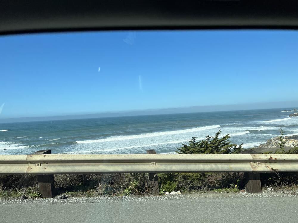
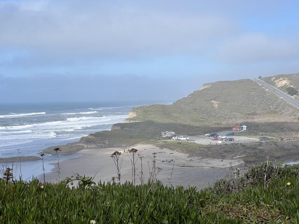
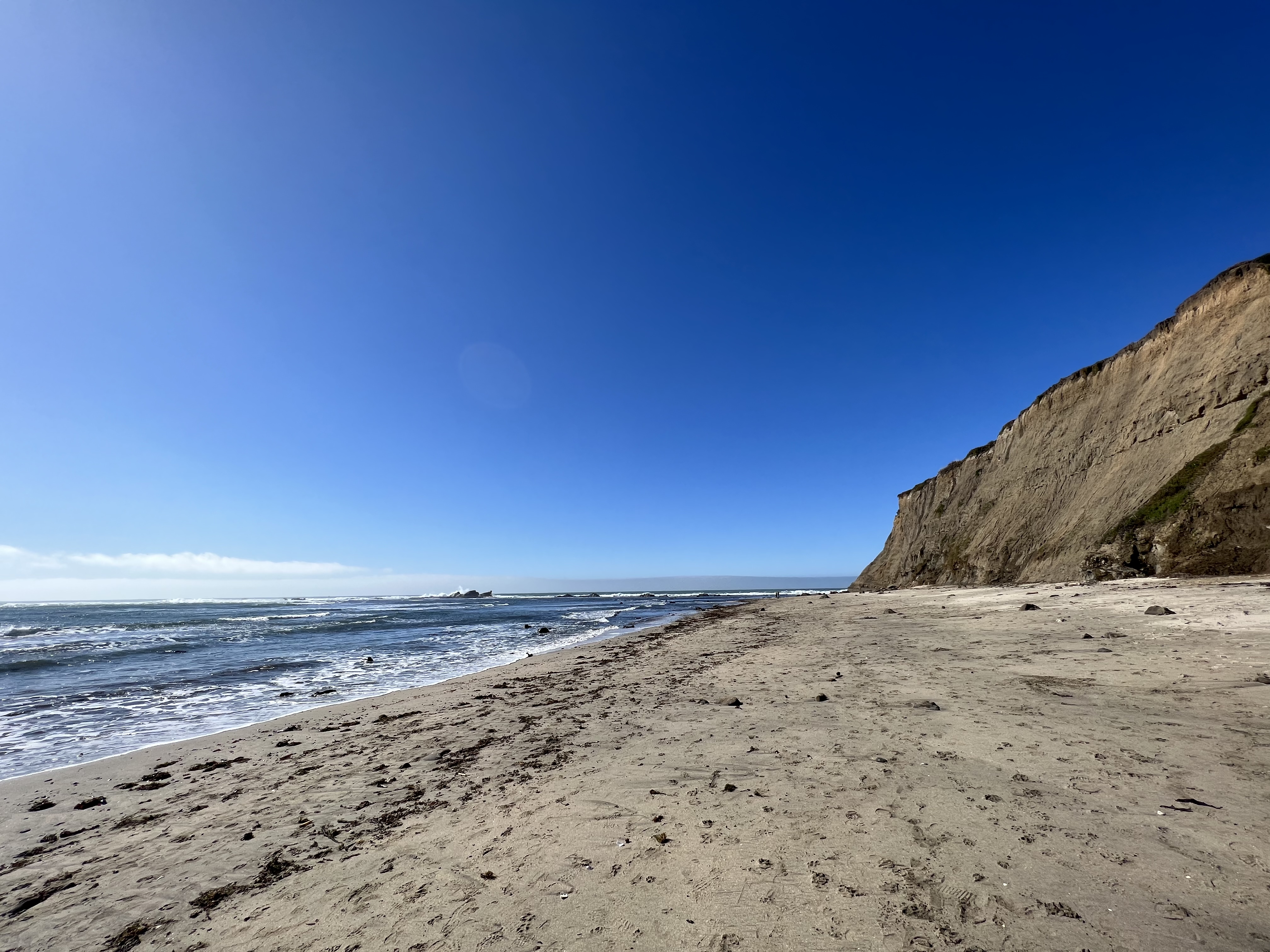
10 pointsStarting yesterday, drove about 120mil north to visit Al and Steve since I’d managed to make it all the way to the left coast and seemed a shame to not close the gap all the way. Had excellent drinks and dinner with the two of them and Claire last night, followed by breakfast this morning after viewing some (smallish) redwoods. Then decided that I should probably take the long way “home” back to Monterey so took Rt1/PCH stopping for a walk and a few photos on the way.


 10 points
 -
6 points
-
4 points
-
Making strides to getting back on the air. First mater of consideration is where I'm going to set up a DJ rig. The second is the time. I think I'm going to still be on Fridays, but start an hour earlier. That means 9PM-11PM Eastern, then of course nearly an hour of yammering on the mic afterward.3 points
-
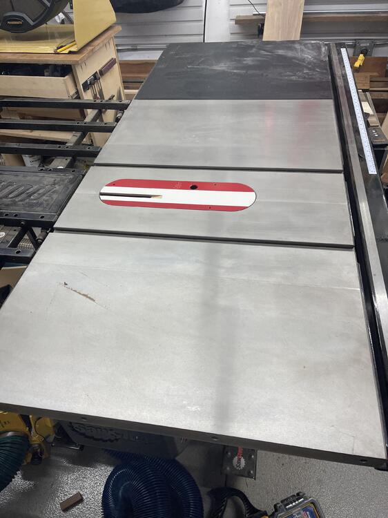
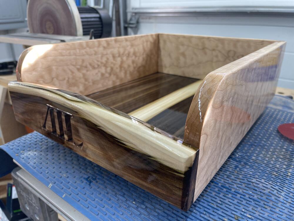
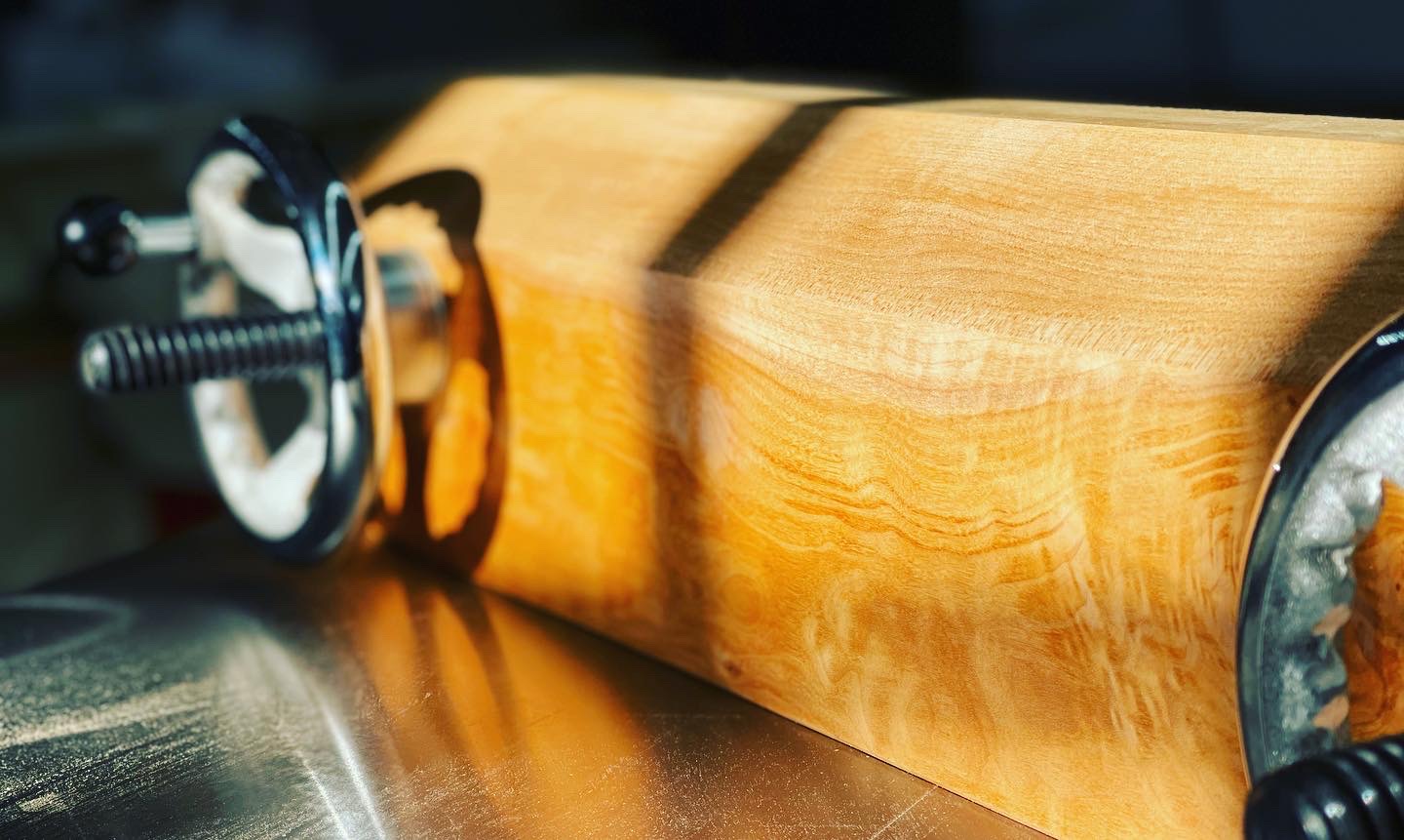
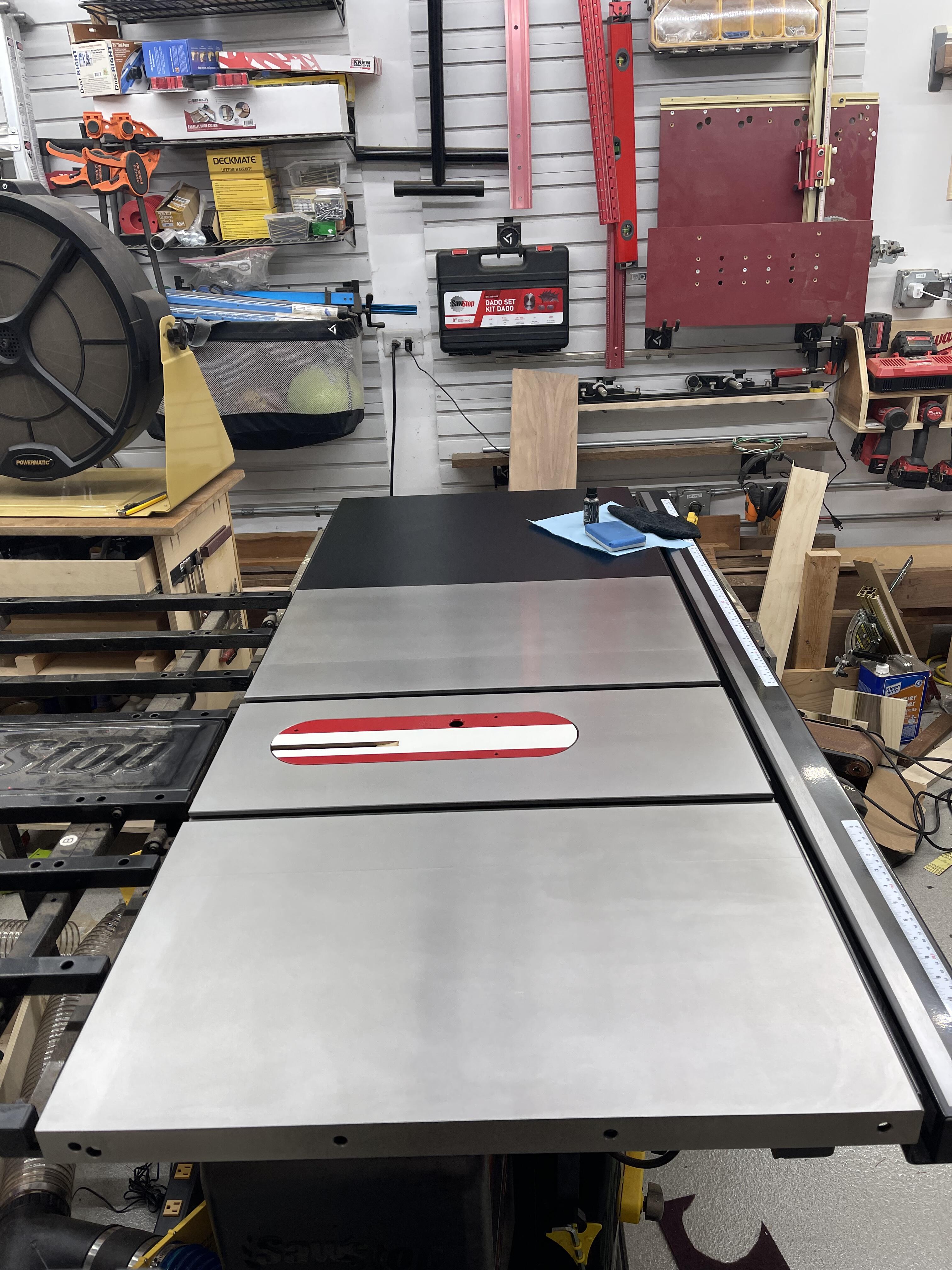
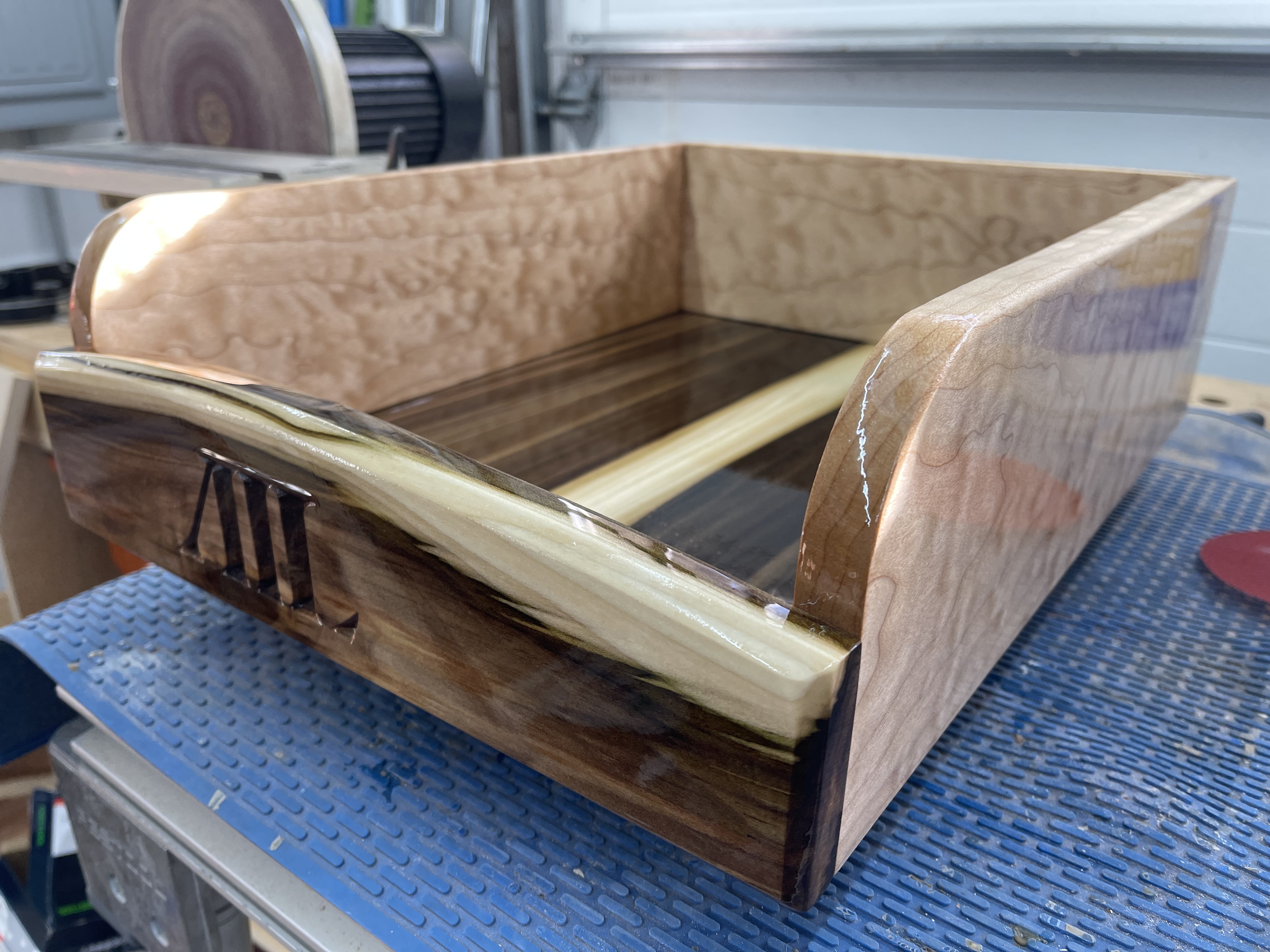
3 pointsIt came out alright. Coated the SawStop and the Planer today with the Carbon Method stuff. Mostly just helped to clean up the top of the SawStop a bit. Probably should have cleaned it more before sealing as it was a bit of a mess and tons of scratches from the Incra sled. Also wrapped up the neverending mail tray project so will be glad to get it out of the shop. Really do not like the shape of this but was not willing to do a ton of work on this Kasia BFF freebie.


 3 points
 -
2 pointsGodspeed, Trugoy... I did the very same, Voltron....I was in grad school and the music was new and fresh and set a great example IMHO. Big loss... HS2 points
-
2 points
-
2 points
-
Strap in, this is gonna be a long walk. As many HCers know, I worked in nightclubs for nearly 20 years and ran my own one man lighting company. At one point I was hugely interested in nightclub and stage lighting. There are many high end club light manufacturers, from Martin to Coemar to ...a company called "High End." The best "luminaries" as they are called are made by an Italian outfit called Clay Paky. Clay Paky fixtures are truly the Ferrari of lighting. Ferrari as the company imagines itself to be, not as they actually are. Clay Paky products fantastically expensive, physically massive, unimaginably heavy and consume gobs of power. 20 years ago I went on eBay and searched for Clay Paky products. It was about what I expected. Huge pieces of kit that was greatly expensive even used, with "freight only" shipping options. One guy was selling an official Clay Paky lighting tech vest for $20. It has a massive Clay Paky logo on the back and a bunch of pockets for ...whatever. I impulsively bought it. I have never actually worn the vest because it's ...pretty stupid looking. Even on stage where one is doing lighting, it looks idiotic. Still, I kept it. For reasons unclear even to me, the Clay Paky vest made it with me to the Vineyard. I found it while doing laundry earlier this week. Amused, I did a search for Clay Paky on eBay, like it was 2003 all over again. Not much has changed. "Set of 4 moving heads + case for $5700 + $$$ shipping." "Package of 8 Mini-B moving heads, $22,000 + freight shipping." There are a few LED options now ("2 color changing LED floods, $7,500." Unlike much of the club lighting industry, Clay Paky were slow to adopt LED technology. LEDs aren't as bright and don't deliver as wide a range of colors as a 750W arc bulb does. Climate change be damned. One listing particularly caught my eye. Most static and moving stage lights come in two styles: matte black finish and boring industrial grey. The former is for nearly all applications and the latter is for stuffy corporate spaces. Custom colors exist, but they're rare. Then there's these fucking things: It's the Clay Paky Sharpy: Trump Edition. They'd fit in just fine here: Note Trump cheaped out and used standard black finish movers.2 points
-
1 pointSome of the other places this topic is discussed have turned into something of a shit show, so I've added this. This forum may get some new members joining, so try and cut them some slack for a bit as they get acclimatized to what head-case can be like.1 point
-
Your 2009 looks like it was more fun than mine. Also, this.1 point
-
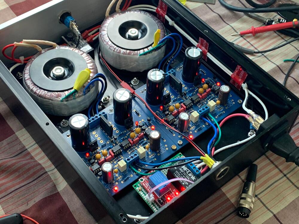
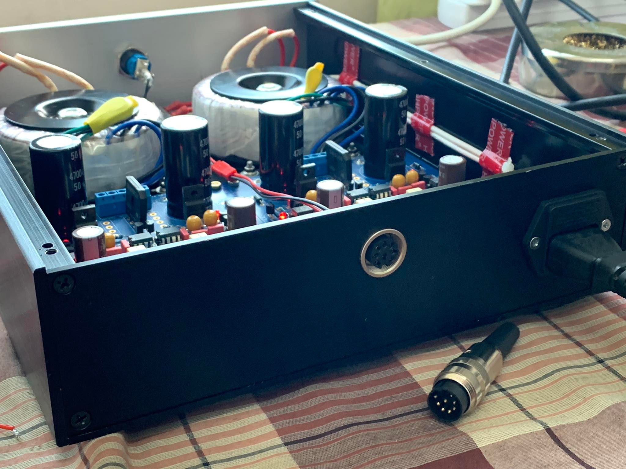
I've heard back from the awesome forum member who's checking out the amp. They found that three of the four MAT BJTs were bad, which is why I didn't notice a difference when I swapped them around. They've replaced them, adjusted the output, and have the unit on its way back to me as I type this out. So, thanks again to them and everyone else here! I can't wait to have it back and look forward to hearing it without concern of that awful static.1 point
-
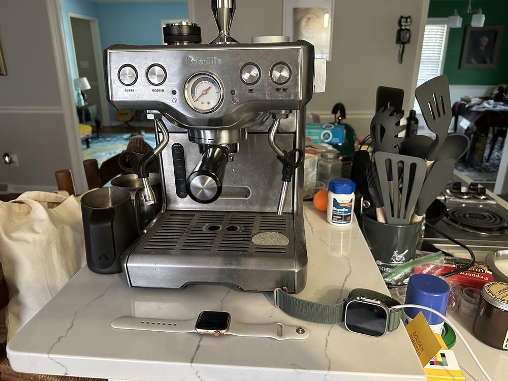
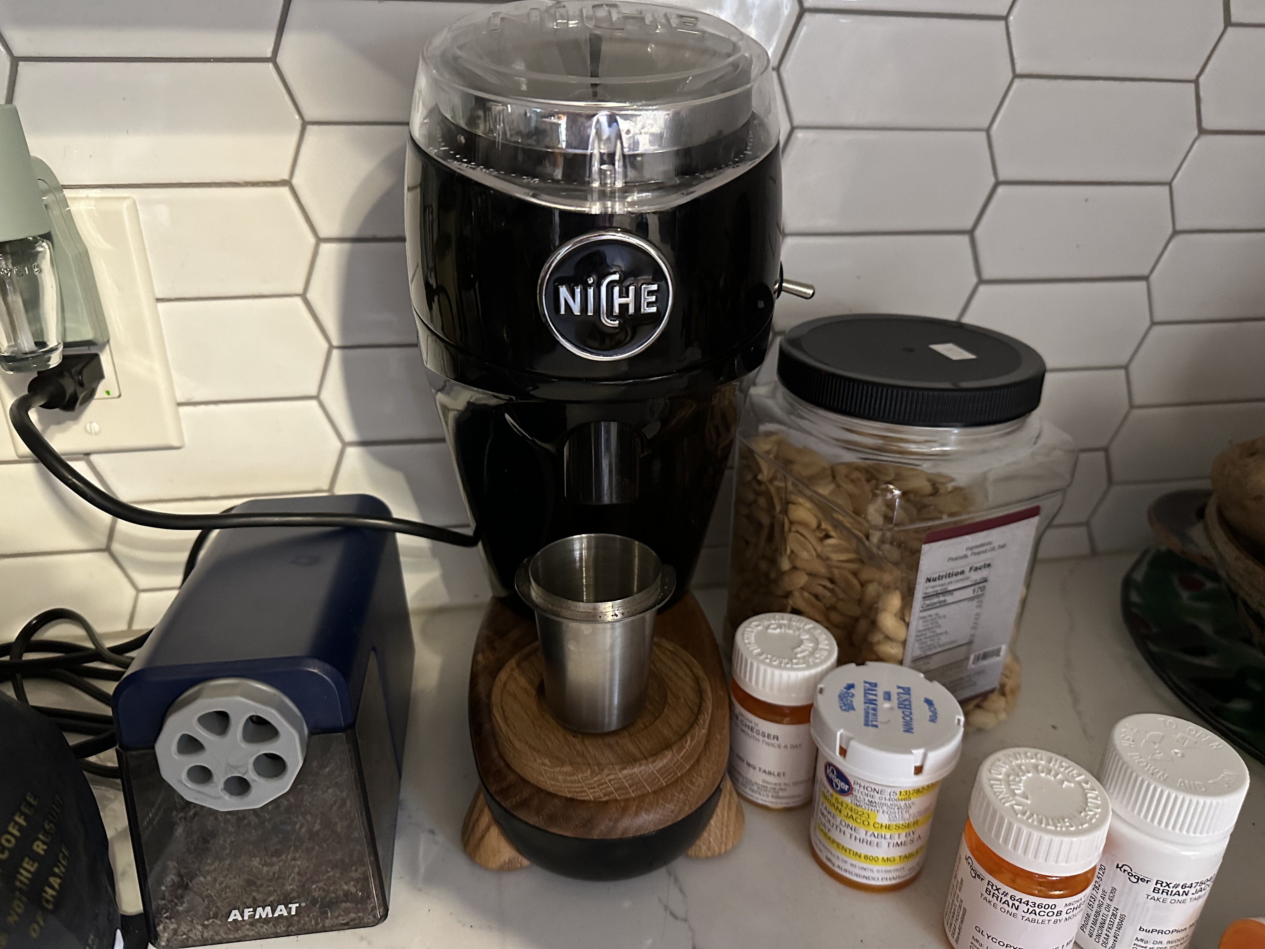
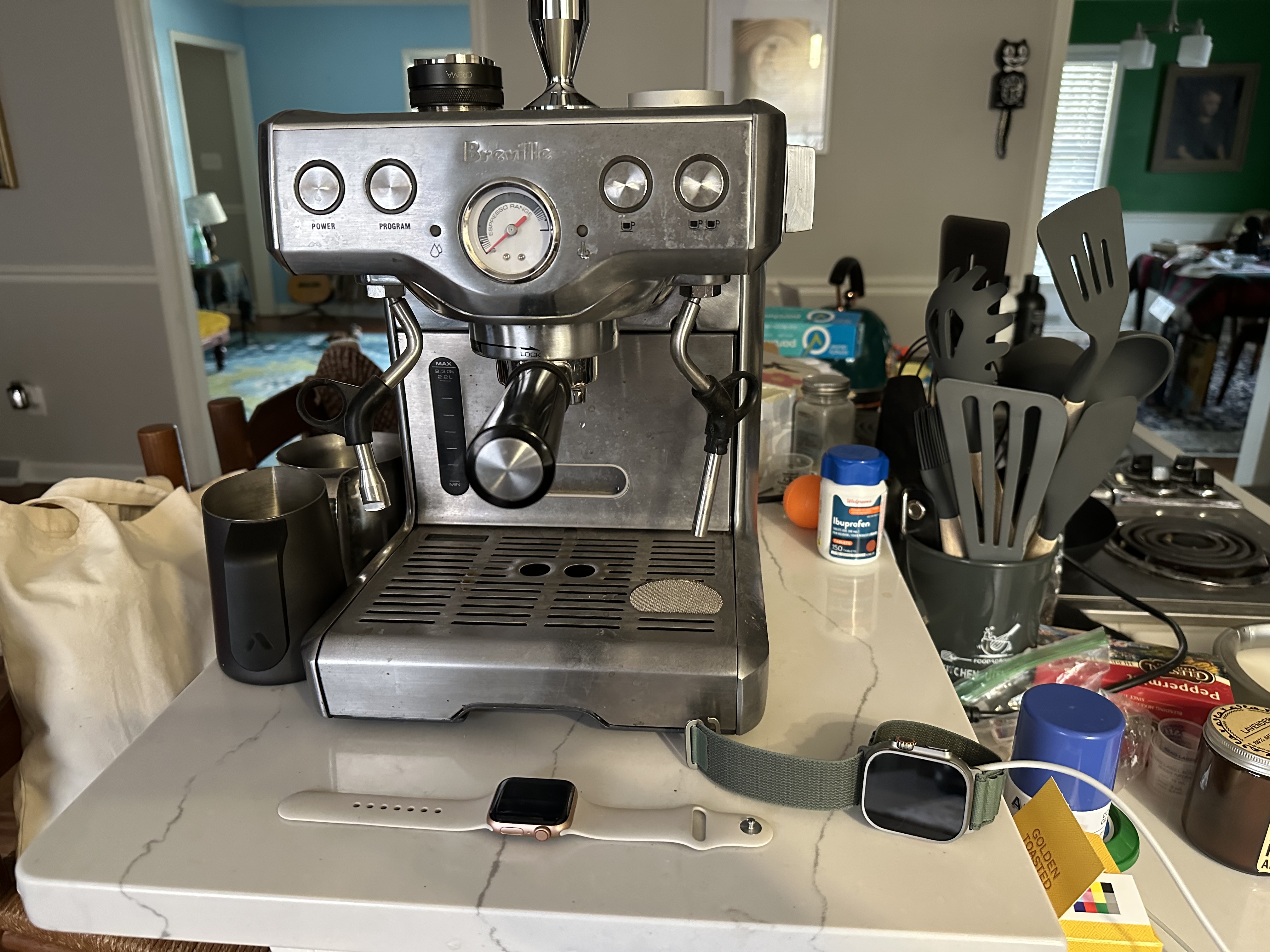
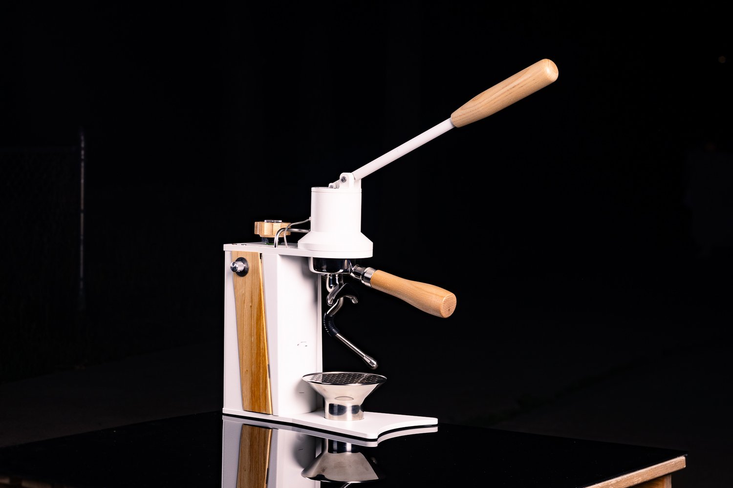
I’m at my partner’s for a couple weeks, so I travelled with the Niche and my little machine. Makes delicious espresso. I’m leaving the machine; Heather is interested in making espresso at home, in which case I should probably leave the Niche here and buy a Lagom P64, since I already have SSP multis in my Ode, which I could stick in the Option-O. The Niche and the little Breville fit in just fine in a busy kitchen.

 1 point
 -
I’ve never cleaned my niche. There aren’t a lot of places for crap to settle in it. That’s awesome, Bryan! I can’t wait to get impressions on both the P100 and the Argos.1 point
-
1 pointI'll add a sub forum for approved users once we're established where the details of less public topics can be discussed outside of the reach of google.1 point
-
12 Stradivari Janine Jansen, Antonio Pappano 2021 https://album.link/i/1577946234 Example: Piano and Violin making sounds together, with the help of a couple of humans. Well done Decca, nice rich recording of good complex performances.1 point
-
Strauss: Ein Heldenleben, Op. 40, TrV 190 - Der Rosenkavalier Suite, Op. 59, TrV 227d: Yutaka Sado & Tonkünstler-Orchester Recommendation from a friend, available on many streaming services: https://album.link/i/1092312481 and Qobuz1 point
-
Glad I got the Lumberg SV80 and KFV80 connectors. Smooth like butter and low profile. 329587661_5880443992073835_6229699499347506353_n.mp4


 1 point
 -
In Feb. 1964, Sgt. Buddy Dresner of the Miami Police Department provided security to the Beatles while they were in town to do Sullivan. They hit it off, and Buddy invited them to have dinner at his home.1 point
-
1 point
-
Odyssey opened a very limited run of spots for Argos this morning that sold out in under 30 minutes. Fortunately I grabbed one in time. Starting with 6 bar for turbo shots + the Bluetooth add on. won’t be here for a while but glad i’m in line now. also my P100 arrives next week so will have a couple months minimum to break in on filter.
 1 point
 -
1 point
-
1 point
-
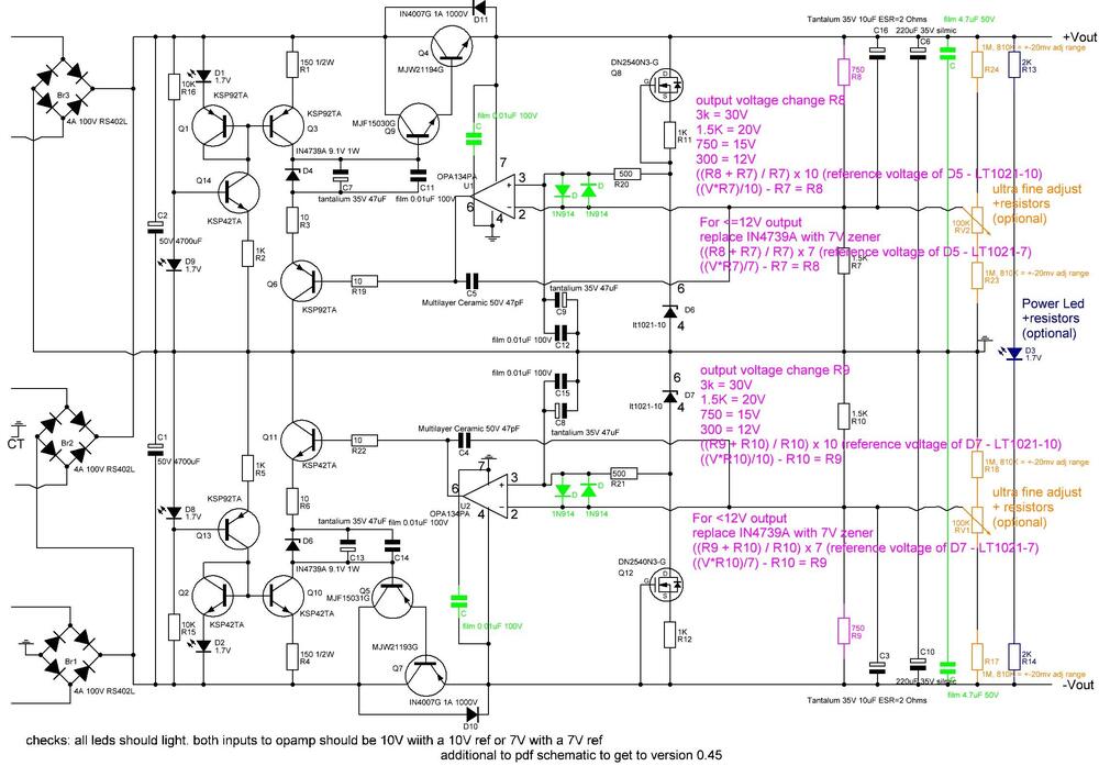
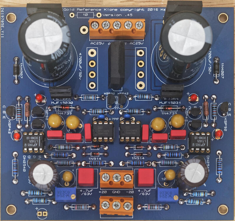
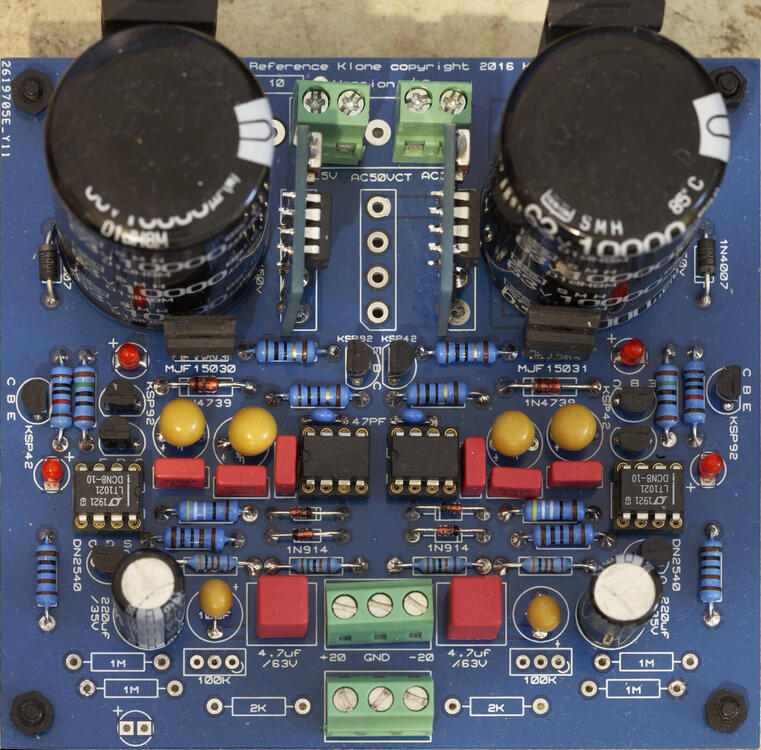
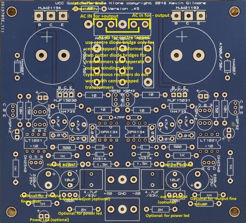
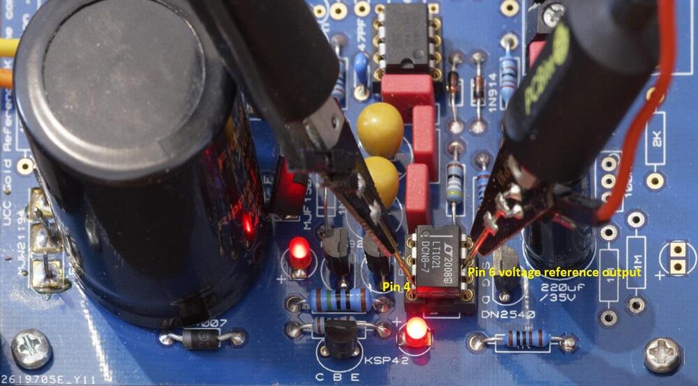
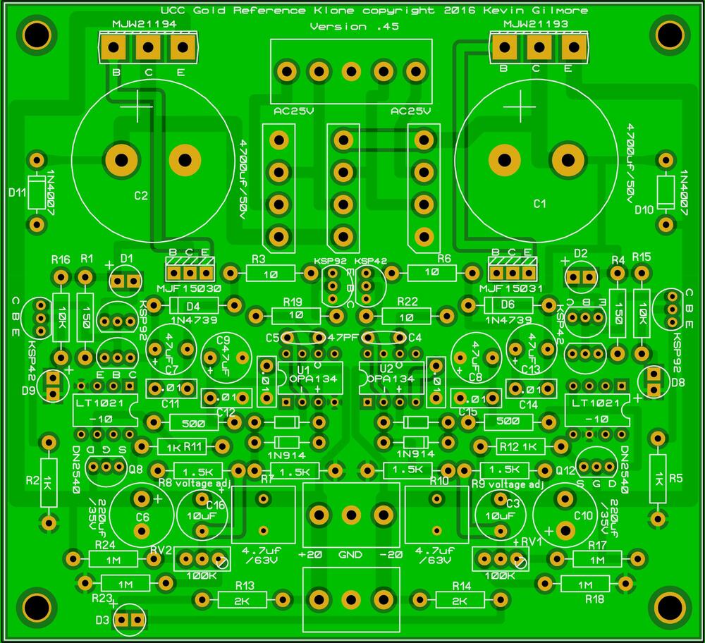
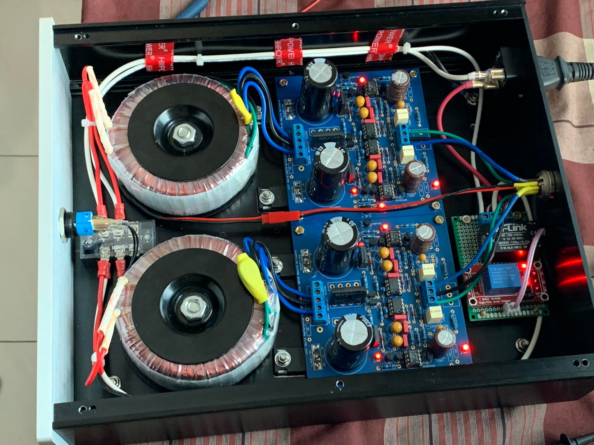
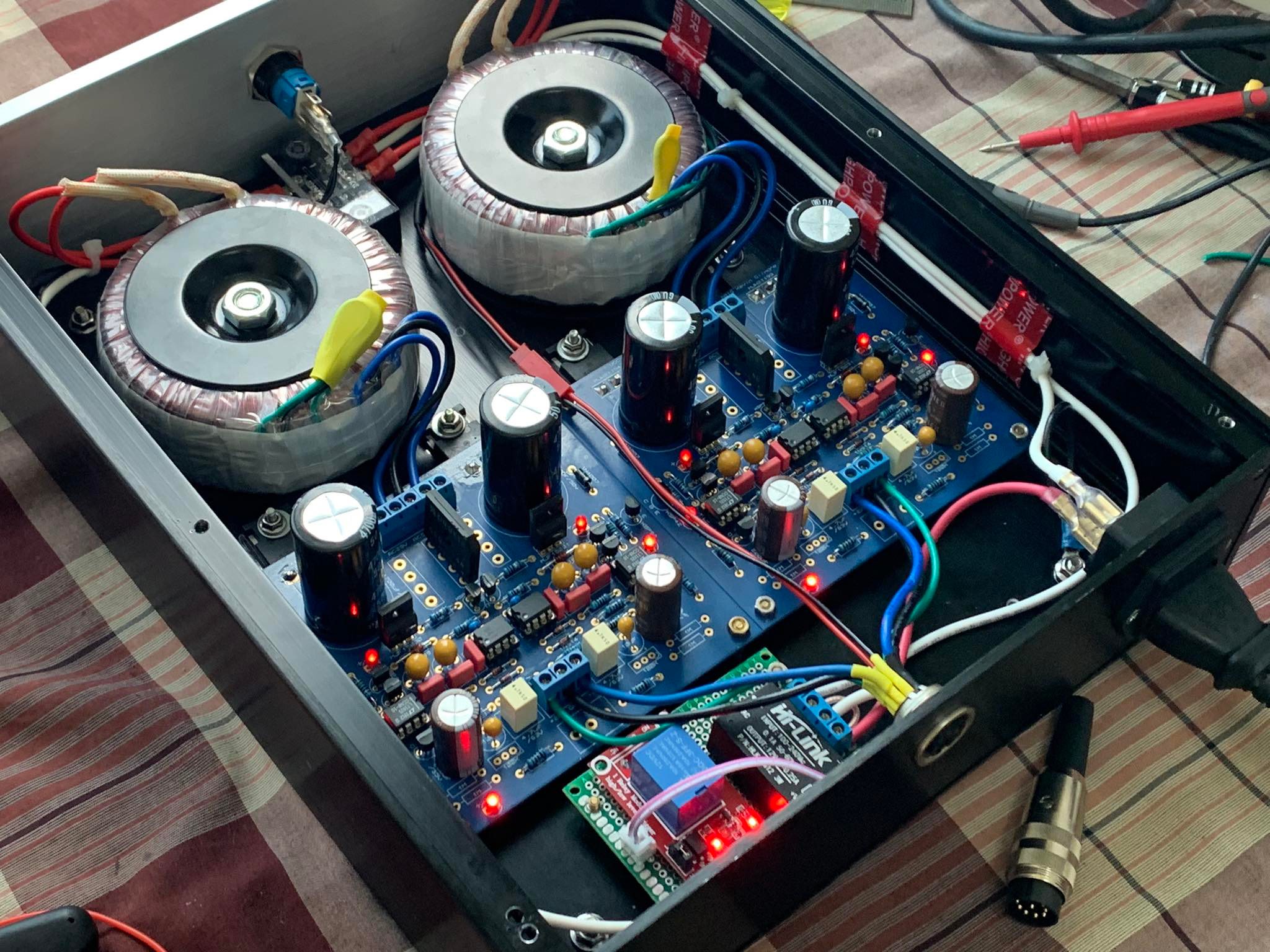
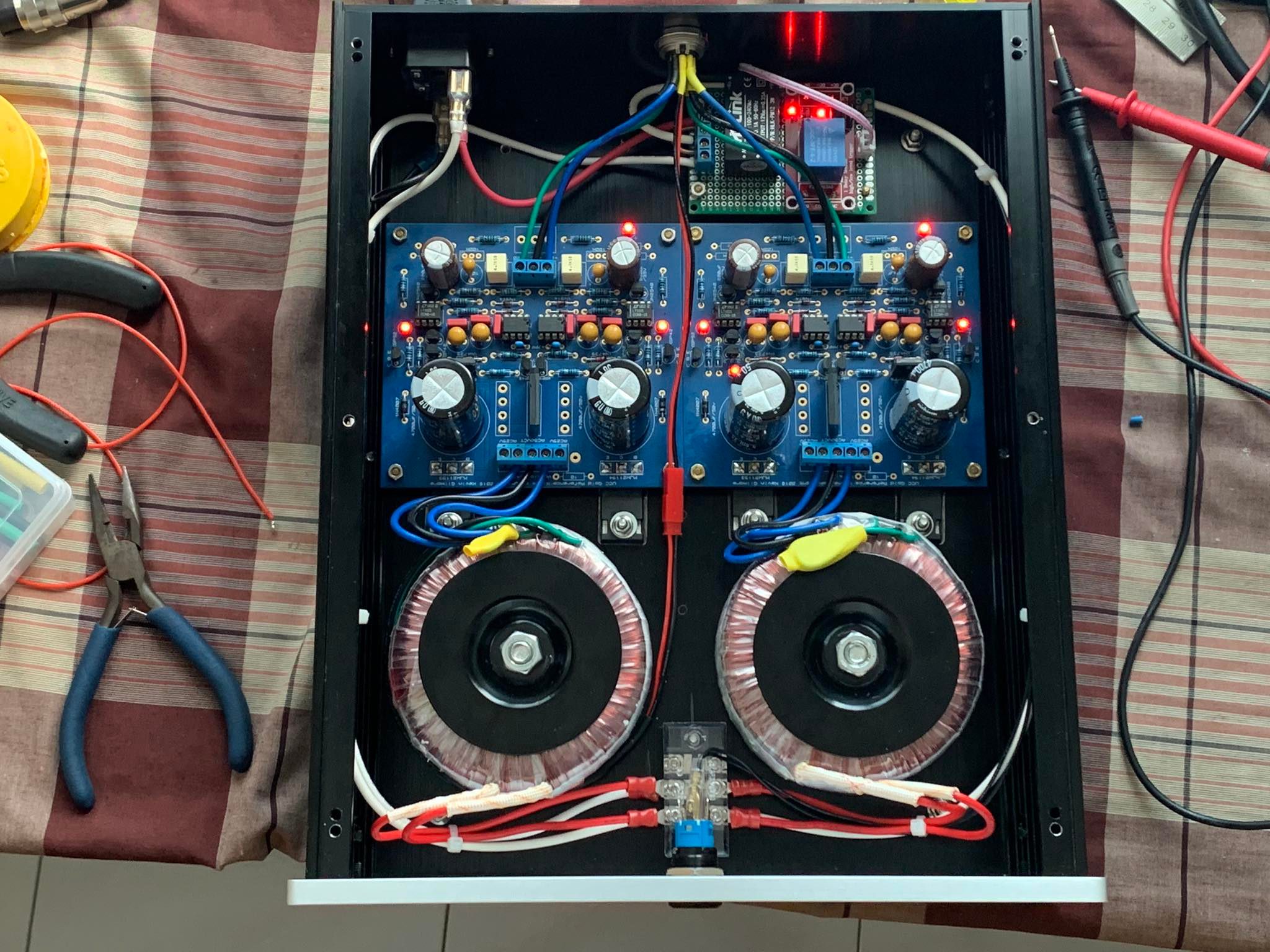
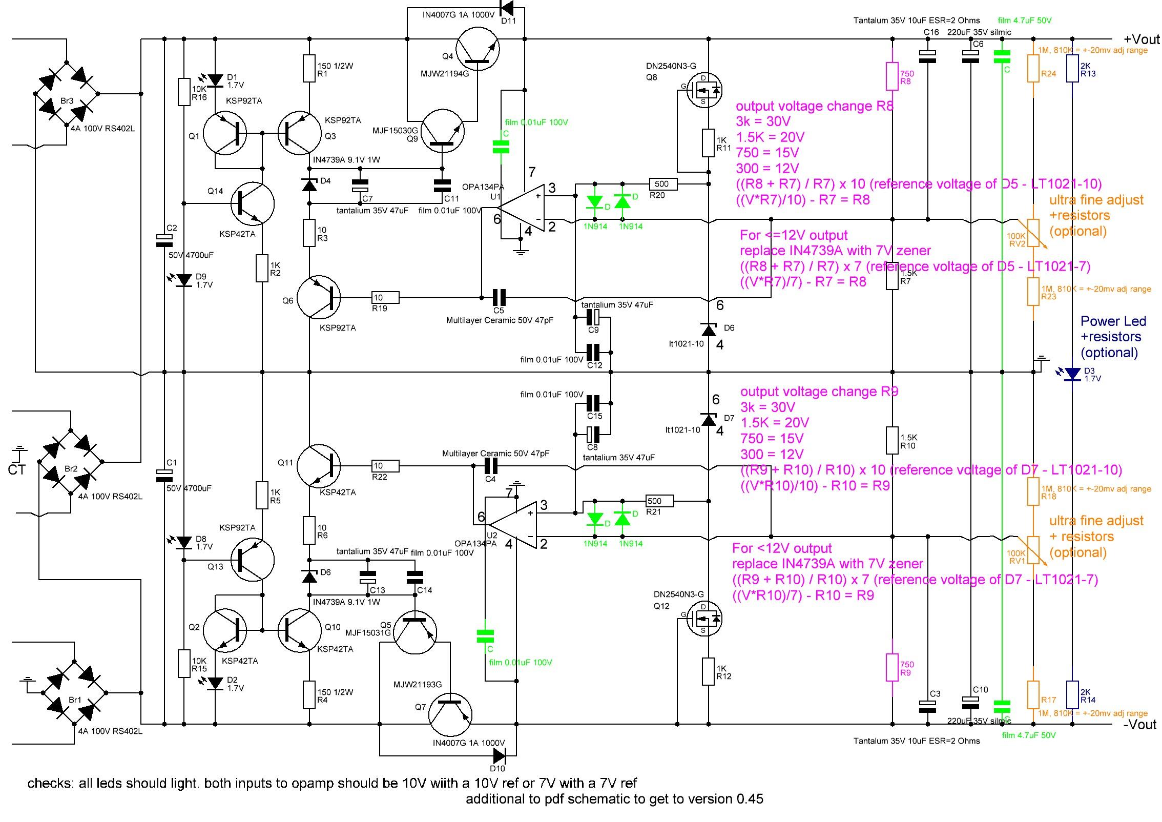
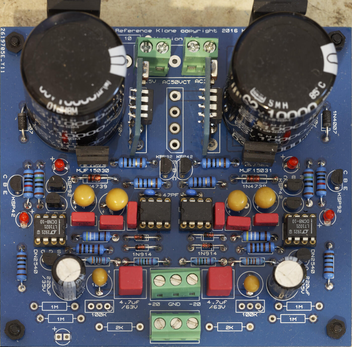
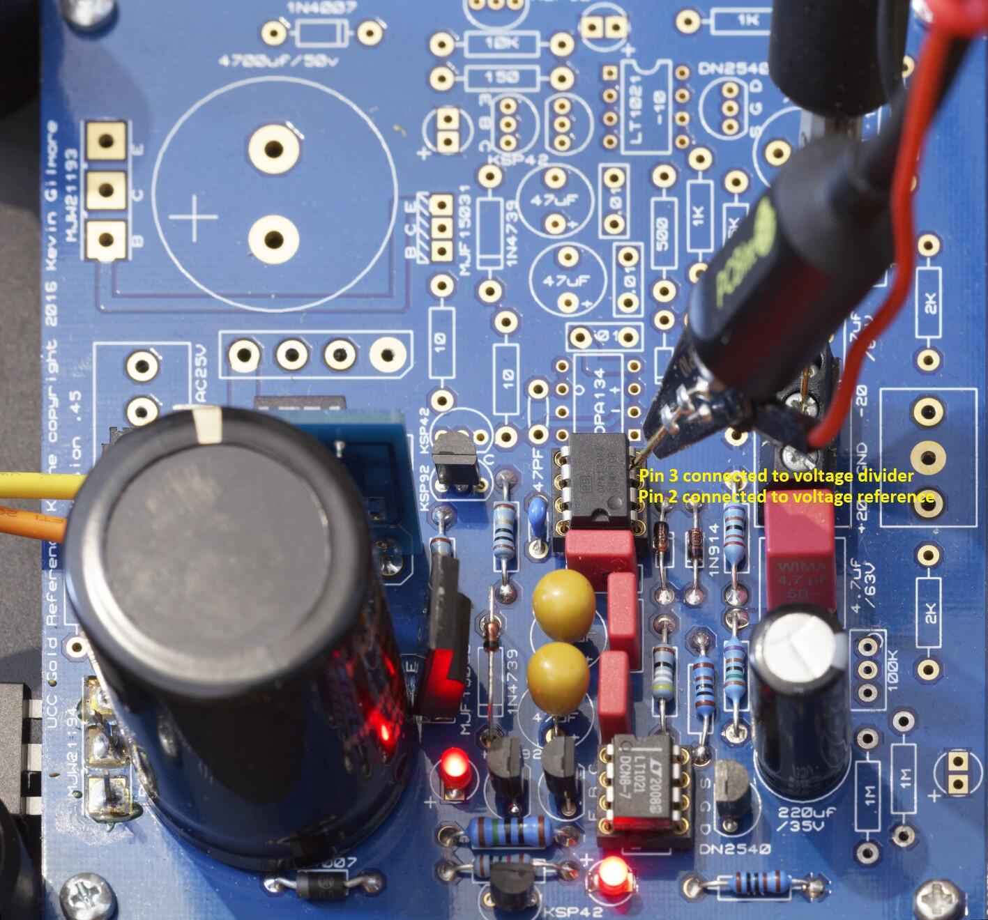
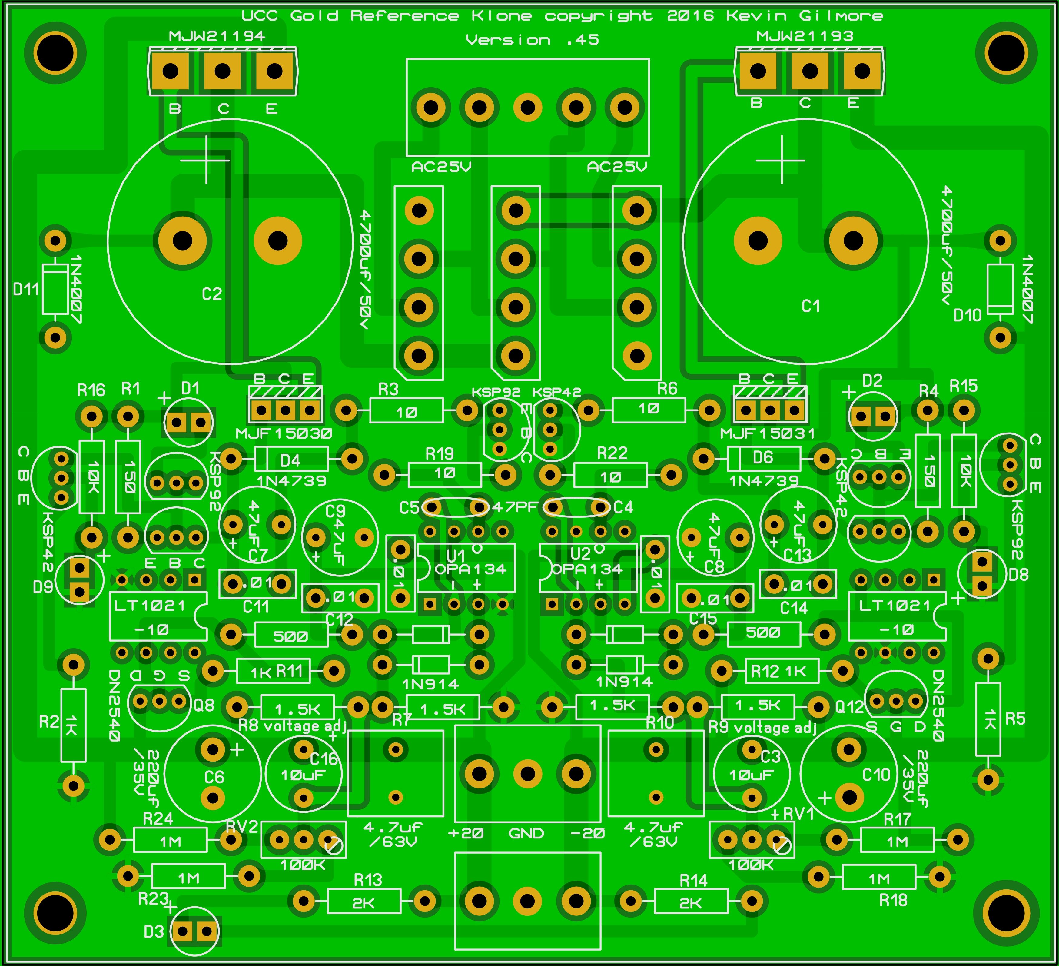
Golden Reference LV Build Guide Schematic for the golden reference LV: parts in green are new additions compared to the published schematic pdf in joamats post above. Parts in purple set the output voltage, parts in brown are the optional fine output adjust and parts in dark blue are the optional power led. Component Layout Optional parts and Options: 1. if you don't want to have a power led fed from the LV board omit the 2K resistors R13, R14 and the led D3 2. if you don't want very fine adjustment of the output voltage omit the 1M resistors R17, R18, R23, R24 and the trimmers RV2 and RV1. If you want more adjustment range reduce the value of the resistors. With 1M ohm resistors the fine adjust can only change the output voltage by a few mV. Replacing with 810K resistors provides a little more adjustment range ~ 20mV but at the expense of decreasing the temperature stability. A cheaper alternative for good output accuracy is to use 1/4W 0.1% low ppm e.g. 15ppm resistors for the voltage set resistors and omit the fine adjust completely - which is cheaper and improves the temperature stability. 3. if you have the dual output board (which has both positive and negative output rails) either you populate the middle diode bridge only and use a transformer which is centre tapped OR you populate the two outer diode bridges and use a transformer with two separate output windings. If use use synchronous rectifiers instead of diode bridges use must use the second option and use separate windings for positive and negative rails. Do not populate all three bridges. If you use a centre tapped transformer you must connect the centre tap to the middle screw terminal (which is connected to the GRLV ground plane) of the 5 terminal AC input block . Do not use a synchronous rectifier to the centre bridge it will not work correctly and can result in the driver mosfets of the synchronous rectifier burning. Note the GRLV cant output less than the voltage of the voltage reference (LT1021), ideally for proper regulation the output needs to be more than about 2V higher than the LT voltage reference. So for about 12V or less output it is recommended you change the 10V reference for a 7V and the zener diodes for a 7V. For 12V output 10V reference or 7V reference can be used but the 7V reference version may have less noise. Maximum output is constrained by the voltage rating of the caps and is about 30V without modifications. Setting the Output Voltage For the positive output R8 and R7 control the output voltage along with the voltage reference, the output voltage is ((R7+R8)/R7)*voltage reference output D5. Assuming you keep R7 at the stock value of 1.5K: output voltage change R8 to 3k = 30V 1.5K = 20V 750 = 15V 300 = 12V In general to calculate R8: ((Voltage required * R7)/voltage reference D5 output) - R7 = R8 For the negative output R10 and R9 control the output voltage along with the voltage reference, the output voltage is ((R10+R9)/R9)*voltage reference output D7. Assuming you keep R10 at the stock value of 1.5K: output voltage change R9 to 3k = 30V 1.5K = 20V 750 = 15V 300 = 12V In general to calculate R9: ((Voltage required * R10)/voltage reference D7 output) - R10 = R9 Photos of finished boards for reference: This version uses a single diode bridge so this is setup for a centre tapped transformer, also has the trimmers and resistors for the power led populated but no power led installed. The build uses 4700uF reservoir caps and silmic 220uf output caps and 1/4w resistors from vishay and dale. This is what you get using the BOM link in this post (see bellow) and is very close to the original BOM published near the beginning of this thread. This version is setup for dual separate transformer windings, and has no power led or trimmers implemented. It also uses synchronous rectifiers instead of diode bridges, nippon chemicon 10000uF reservoir caps, Panasonic FR series 220uF caps and 1/2W 50ppm 1% koa resistors. The resistors that set the output voltage are 1/4W TE 0.1% 15ppm for increased temperature stability and output accuracy. This is my current default build. BOM (based on 10V voltage reference and all options being populated) https://www.mouser.com/ProjectManager/ProjectDetail.aspx?AccessID=edda1bdbf7 Component list with cap size information Br1,Br2,Br3 = 2 x 4A 100V RS402L use 2 for dual winding transformer use 1 for centre tapped transformer C,C = 2 x film 4.7uF 50V 5mm lead spacing 0.5mm lead diameter C,C,C11,C12,C14,C15 = 6 x film 0.01uF 100V 5mm lead spacing max size ~ 7.6mmx3mm 0.5mm lead diameter C1,C2 = 2 x 50V 4700uF 10mm lead spacing max diameter 25mm, 22mm more comfortable fit main reservoir cap I also use Nippon Chemicon 63V 10000uF which just fit. C3,C16 = 2 x Tantalum 35V 10uF ESR=2 Ohms 5mm lead spacing 0.5mm lead diameter C4,C5 = 2 x Multilayer Ceramic 50V 47pF 5mm lead spacing 0.5mm lead diameter C6,C10 = 2 x 220uF 35V silmic or Panasonic FR series 5mm lead spacing 12.5mm max diameter C7,C8,C9,C13 = 4 x tantalium 35V 47uF ESR=0.8ohms 5mm lead spacing 0.5mm lead diameter D,D,D,D = 4 x 1N914 D1,D2,D3,D8,D9 = 5 x 1.7V red led 4 are required one is for optional power led leally all 4 main leds should be from the same batch and have similar characteristics. D10,D11 = 2 x IN4007G 1A 1000V D4,D6 = 2 x IN4739A 9.1V 1W use 7V zener for <=12V output D6,D7 = 2 x lt1021-10 10V voltage reference use 7V for <=12V output Q4 = 1 x MJW21194G Q5 = 1 x MJF15031G Q7 = 1 x MJW21193G Q9 = 1 x MJF15030G Q1,Q3,Q6,Q13 = 4 x KSP92TA Q2,Q10,Q11,Q14 = 4 x KSP42TA Q8,Q12 = 2 x DN2540N3-G R1,R4 = 2 x 150 1/2W R13,R14 = 2 x 2K R15,R16 = 2 x 10K R17,R18,R23,R24 = 4 x 1M, 810K = +-20mv adj range optional for fine adjustment R2,R5,R11,R12 = 4 x 1K R20,R21 = 2 x 500 R3,R6,R19,R22 = 4 x 10 R7,R10 = 2 x 1.5K R8,R9 = 2 x 750 for 15V output change as necessary for your output RV1,RV2 = 2 x 100K optional for fine adjustment U1,U2 = 2 x OPA134PA opamp Building Once you have decided the build options and output voltage, construction is straightforward given there are no high voltages. Depending upon the current draw the large power transistors on the side of the board may require heatsinking. The metal tab is live so they will need to be insulated from the heatsink/chassis. Socketing the reference and opamps is optional but it does make replacement and reuse easier. Make sure the caps are installed with the correct polarity. The line on the tantalums denotes the positive Terminal whereas the line on electrolytic caps denotes the negative terminal.... the film caps can be installed either way around as can the small ceramic caps. For the leds the longer leg is the + leg and this goes to the + mark on the pcb be careful to install the opamps and voltage reference chips the correct way around they will get very hot very quickly if installed the wrong way. make sure you don't place as ksp42 where a ksp92 should go of visa versa. Its easy to do since they look identical and its not easy to see all the markings once populating the board is finished. Testing (optional) If you have a means to control the input voltage to the board e.g. a variac, then with no load connected to the grlv the outer leds (closest to the LT voltage reference) should just start to glow at about 2.4 to 2.5VAC rms input voltage to the board and the output of the GRLV should be around 1V DC. If you cant get the outer leds to light with about 3VAC rms input, stop and disconnect, something is definitely wrong. By 3VAC rms the outer leds should be bright. Increasing the variac output further should see proportional rises in the GRLV DC output voltage until the output reaches the expected output. At this point the inner leds closest to the zener diode may not have lit and although basic regulation has been achieved, the input voltage is too low for full low noise regulation. Increase the input voltage a little more and the inner leds should light. This should happen with after about an additional 1 volt AC rms is added to the input. The output voltage should not increase. As a very rough rule of thumb, without load, the grlv needs about 2V less input AC rms than its DC output. So for example for 12v output expect regulation to just happen at about 10VAC rms input but the inner led not to light until about 11VAC rms. Note this figures depend on tolerances, the diode bridge voltage drop, led characteristics etc and are a rough guide only. Adding a load to the GRLV will mean it needs a higher input voltage in order to regulate since some of the sources of voltage drops are dependant on current draw e.g. the diode bridges. So if you adjust the variac to just get the inner led lit with no load don't be surprised if it goes out when you draw a few hundred milliamps. Another way to test is to connect the AC in of one rail to a current limited DC power supply. Set the current limit to say 0.010A (10mA) and slowly increase the voltage. Bellow about 3.3VDC input to the GRLV there should be low current draw <10mA. At about 3.4VDC the outer led will start to light and current draw should still be <10mA. Around 8.5VDC input current draw should reach about 10mA. The inner led close to the main cap should begin to light at about 2.6VDC input above the expected output e.g. 14.6VDC input for 12V output. At this point current draw should be about 20mA and you may need to increase your DC power supply current limit. Increasing the DC power supply output past this point should not result in increasing current draw or increasing GRLV output. Note when you increase the DC power supply voltage you will get an initial current draw spike as the input cap charges to the new voltage level but the current draw should quickly subside to the figures shown. If the GRLv regulates and behaves as expected with no load and has no warm components or varying output then you could continue to load testing. The reality is that if your RLV works with no load its almost certainly ok and will be fine without load testing. But if you want to be extra careful the easiest way to do this is with an electronic DC load. I setup my load so that it will abort the test if the output voltage of the GRLV exceeds 0.2V above or bellow the no load output. A properly working GRLV with enough input voltage will vary very very little with current draw - much less than a traditional 78xx/79xx voltage regulator. I then load at 50mA and check for hot components, and then in 100mA steps up to 1A. Above about 400mA the large main transistors will get hot if they are not heatsinked... this is normal as the current draw increases there is more power dissipation in the transistor. Note transformers and diode bridges etc do drop more voltage as the current draw increases so if the inner led goes out at higher current draws check the input voltage to the GRLV has not decreased too much for the GRLV to regulate. Don't load test about above 300mA for long periods without heatsinking the main transistors. Additional Checks (useful if troubleshooting) The voltage reference output voltage should be present between pins 4 and 6 of the LT reference and be stable and very close to the spec sheet voltage. Use fine tip probes and be careful not to short any pins together when probing: The opamp compares the voltage reference with the output voltage from the voltage divider (the resistors which set the output voltage) and creates a correction signal. Pin 2 of the opamp is connected to the voltage reference and pin 3 is connected to the voltage divider. When working correctly, the voltages with respect to ground to pin 2 and from ground to pin 3 should be identical and be the same as the output of the voltage reference measured above. In circuit testing and troubleshooting So its not working correctly or you want to do some more tests before powering on for the first time?. Here are some tests you can do on a fully built GRLV that has no power connected. With a multimeter set to diode check mode and the caps on the grlv fully discharged. you can do some sanity checks. The exact measurements will vary from multimeter to multimeter and device to device but this should give some ball park figures. My figures are based on a Brymen bm869s. Led polarity outer leds closest to the edge of the pcb and the voltage reference: red lead of multimeter to + lead of led, black on - lead of led ~ 0.8V slowly rising as a cap charges led does not light. leads reversed: 1.63V slowly rising led does not light inner leds closest to the main input filter caps: red lead of multimeter to + lead of led, black on - lead of led ~ 1.7V stable voltage led should light. leads reversed: over range / OL / open circuit, led does not light. Zener check both zeners close to the inner leds: red probe on band side black on non band side: OL / open circuit, probes reversed 0.66V Transistor Death/Incorrect Placement Checks large MJW21194 on +rail measuring looking at the front of the transistor where the markings are: red probe on left pin black on middle pin: 0.46V steady, probes reversed OL / open circuit red probe on left pin black on right pin: 0.48V steady, probes reversed OL / open circuit red probe on middle pin black on right pin: 0.5V rising rapidly, probes reversed 0.48V rising much more slowly large MJW21193 on -rail measuring looking at the front of the transistor where the markings are: red probe on left pin black on middle pin: OL / open circuit , probes reversed 0.48V steady red probe on left pin black on right pin: OL / open circuit, probes reversed 0.49V steady red probe on middle pin black on right pin: 0.48 rising slowly, probes reversed 0.5V rising much more rapidly MJW15030 on +rail next to inner led: red probe on left pin black on middle pin: 0.57V steady, probes reversed OL / open circuit red probe on left pin black on right pin: 0.57V steady, probes reversed OL / open circuit red probe on middle pin black on right pin: OL / open circuit , probes reversed 0.46 steady MJW15031 on -rail next to inner led: red probe on left pin black on middle pin: OL / open circuit, probes reversed 0.57V steady red probe on left pin black on right pin: OL / open circuit probes reversed 0.57V steady red probe on middle pin black on right pin: 0.48 steady probes reversed OL / open circuit KSP42 on +rail on edge of board: looking at flat front where the marking are red probe on left pin black on middle pin: 1.8V rising, probes reversed 0.6V steady red probe on left pin black on right pin: 1.2V rising, probes reversed OL / open circuit red probe on middle pin black on right pin: 0.6V steady probes reversed OL / open circuit KSP92 on -rail on edge of board: looking at flat front where the marking are red probe on left pin black on middle pin: 0.61V steady, probes reversed 1.7V rising red probe on left pin black on right pin: OL / open circuit. probes reversed 0.9V rising red probe on middle pin black on right pin: OL / open circuit, probes reversed 0.6V steady DN2540 on +rail between voltage reference and 220uf output cap red probe on left pin black on middle pin: 0.31V steady, probes reversed 0.32V steady red probe on left pin black on right pin: 0.004V steady. probes reversed 0.004V steady red probe on middle pin black on right pin: 0.32V steady, probes reversed 0.32V steady DN2540 on -rail between voltage reference and 220uf output cap red probe on left pin black on middle pin: 0.32V steady, probes reversed 0.32V steady red probe on left pin black on right pin: 0.004V steady. probes reversed 0.004V steady red probe on middle pin black on right pin: 0.32V steady, probes reversed 0.32V steady KSP92 on +rail near centre of board close to middle diode bridge: looking at flat front where the marking are red probe on left pin black on middle pin: 0.6V steady probes reversed OL / open circuit red probe on left pin black on right pin: 1.0V rising slowly, probes reversed OL / Open circuit red probe on middle pin black on right pin: rises to about 0.67V, probes reversed 0.56 steady KSP42 on -rail near centre of board close to middle diode bridge: looking at flat front where the marking are red probe on left pin black on middle pin: OL / Open circuit, probes reversed 1.61V steady red probe on left pin black on right pin: OL / open circuit. probes reversed 0.95V rising red probe on middle pin black on right pin: 0.59V steady, probes reversed 0.67V steady the pair of KSP92 on +rail ksp92 closest to voltage ref: looking at flat front where the marking are red probe on left pin black on middle pin: 0.62V steady probes reversed OL / open circuit red probe on left pin black on right pin: OL / open circuit, probes reversed 0.61 steady red probe on middle pin black on right pin: OL open circuit, probes reversed 0.61 steady the pair of KSP92 on +rail ksp92 closest to the inner led: looking at flat front where the marking are red probe on left pin black on middle pin: 0.59V steady probes reversed OL / open circuit red probe on left pin black on right pin: 0.59V steady, probes reversed OL / open circuit red probe on middle pin black on right pin: 0V / short, probes 0V / short the pair of KSP42 on -rail ksp42 closest to voltage ref: looking at flat front where the marking are red probe on left pin black on middle pin: OL / open circuit, probes reversed 0.59V steady red probe on left pin black on right pin: OL / open circuit , probes reversed 0.59V steady red probe on middle pin black on right pin: 0V / short, probes 0V / short the pair of KSP92 on +rail ksp92 closest to the inner led: looking at flat front where the marking are red probe on left pin black on middle pin: OL / open circuit, probes reversed 0.61 steady red probe on left pin black on right pin: 0.62V steady probes reversed OL / open circuit red probe on middle pin black on right pin: 0.61V steady, probes reversed OL open circuit Good luck with your build and thank you to everyone who contributed to the design of the GRLV and this thread.

 1 point
 -
0 pointsRIP to Plug Two, Trugoy the Dove of De LA Soul at age 54. I played the shit out of their first album when it came out, and we saw them play at Cornell that year. Sad. 😢 https://www.rollingstone.com/music/music-news/de-la-soul-trugoy-the-dove-dead-obit-1234678463/amp/0 points
-


Important Information
By using this site, you agree to our Terms of Use.