

Leaderboard
-
Voltron
High Rollers37Points34512Posts -
n_maher
Administrators11Points27458Posts -
shellylh
High Rollers7Points18862Posts -
Augsburger
High Rollers6Points13165Posts


Popular Content
Showing content with the highest reputation on 11/24/15 in all areas
-
13 pointsToday I proved that I can bring home the bacon and fry it up in a pan. I mixed & poured concrete while simultaneously baking cookies. And I even did a little lawyering in the middle. Importantly, I marked the foundation with cryptic symbols.13 points
-
6 pointsThanks everyone. We actually got a bit of good news today... They were actually able to spay the pup today, and she's doing well, so we'll be able to pick her up Saturday!6 points
-
2 pointsMy mom made lasagna...& there was cheesecake... Both my dad & sister included a monetary donation with their expressions of love... neat(!) referred to how I took my first pull of HH 6y BiB before switching over to HH & lemonade:)...I'm chilling some Prairie Artisan Vanilla Noir & tucked away a bottle of Goose Island (Global MegaCorp) Bourbon County Rare 2015 for a later date... & work didn't suck too hard...Let's call it a win!... I'm probably just going to relax the rest of the night...See if there are any Humphrey Bogart movies I have yet to see... Thanks, everybody...2 points
-
2 points
-
2 pointsGot an email from HDTracks, TODAY THRU NOVEMBER 30TH, 2015 Get 20% off the Top Female Artists at HDtracks.com AGON Members Only: Use this code DIVASHD202 points
-
Thanks for reporting that, looks like they broke something in the small upgrade yesterday. I've been able to disable the guest page caching that was causing it for the time being.1 point
-
I was going to post this, but yep, if you're not signed in you can't see anything. **BRENT**1 point
-
If I don't log into head-case it gives me: Sorry, there is a problem Something went wrong. Please try again. Error code: EX21 point
-
1 point
-
1 point
-
1 point
-
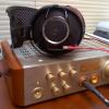
Circlotron Driver board from the Group Buy is working. As I'd like to test as much as possible before connecting everything, I'd decided to hook the driver up as an amp. The Carbon V5 and Circlotron driver board are very similar although there are a number of differences that require a bit of tweaking to make it work. The biggest difference is in the servo part of the driver board and since the driver board is missing the A06 - controlling the current in the tail of the output stage directly from the opto - it is probably not possible to run the output stage at 20mA as it will exceed the opto current capabilities. The pic shows (I believe) everything needed to 'convert' the driver into an amp - I haven't tried to get the servo to work though. The important alterations is: (not including servo - amp only) NOT populating the 10k/10uF besides the opto terminal (until it is actually gonna be used that is) parallel the 500ohm in the tail of the output stage with 150ohm or thereabouts (I just solder one on top - easy to remove again) adding 2x (100k + 100k) for feedback. adding 2x 5k1 ballast resistors to the output This is as I hook'ed it up, and dialed it in for 20mA operation - has ran for some days 24x7 without any problems. For the servo to work a few changes in addition to the picture above is needed: the opto has leg2 tied to GND - this trace needs to be cut. Remove: the 47uF between the opto leg1 and leg2, and 5k resistor between OpAmp leg6 and opto log1 Add: 1uF between OpAmp leg6 and leg2, 200ohm between OpAmp leg6 and opto leg 2, and GND to opto leg11 point
-
1 pointThe residue is a film of fine flux, broken down by the alcohol. You may need to do several applications with the alcohol before the board becomes squeaky clean, but the isopropyl alcohol is all you need. Each application needs a fresh batch of alcohol and the toothbrush needs a good rinse in between applications, unless you have several clean fresh ones. I'm fairly liberal and use a good amount with each pass.1 point
-
1 point
-
1 point
-
1 point
-
1 pointI can't say it enough, you guys are very kind! Much obliged. Having a great evening. As a follow up, I am looking forward to putting in some cycling miles this coming Holiday weekend.1 point
-
1 point
-
1 pointI can't speak directly about the Kontact stuff but my luck with "flux removers" in general was very poor until I tried simple 90+% isopropyl alcohol. I think the alcohol was cheaper too.1 point
-
1 pointGet the purest isopropyl alcohol that you can find in a decent quantity and several sacrificial tooth brushes. Lather, rinse, repeat until clean. Manage the waste appropriately.1 point
-
1 pointI'm loving the second season of Fargo (loved the first season too). The characters are fantastic. 90% are so friggin clueless that it can drive you a little nuts but that's just part of the fun. I wondered why the episodes were an hour 20 min but I think that maybe the show is a full 60 minutes (plus 20 min of non-show)? If you love the Coen Brothers, you'll probably agree with me.1 point
-
1 point
-
1 pointJust thought I'd mention that AudioXpress has published both parts of my SRX Plus article, and I've completed the discussion of its design in the SRX revisited thread. Dr. Gilmore has board files on the amplifier. One of these days when I've got the time I might design a board for the power supply but it's simple enough to be built point-to-point.1 point


Important Information
By using this site, you agree to our Terms of Use.