

Leaderboard


Popular Content
Showing content with the highest reputation on 06/18/20 in Posts
-
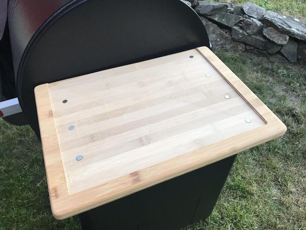
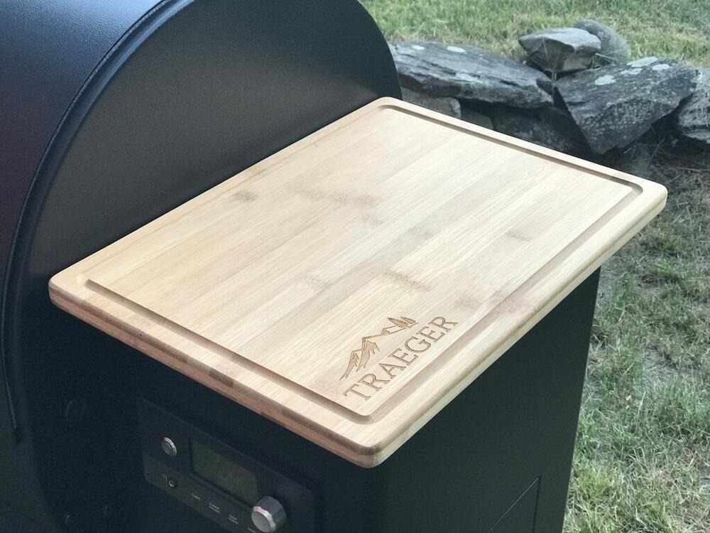
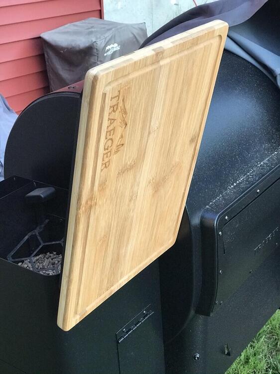
18 pointsYou inspired me to get off my ass and work on my first real mod for the Traeger, a magnetic cutting board to mount to the top of the pellet hopper. I used the Shapeoko to machine a pocket into the back side of the cutting board as well as to make the recesses for the magnets. Then used the laser engraver to etch Traeger's logo into the top. I'll probably make a fancier version at some point but this will do for now.
 18 points
 -
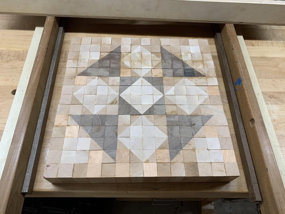
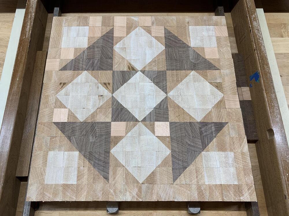
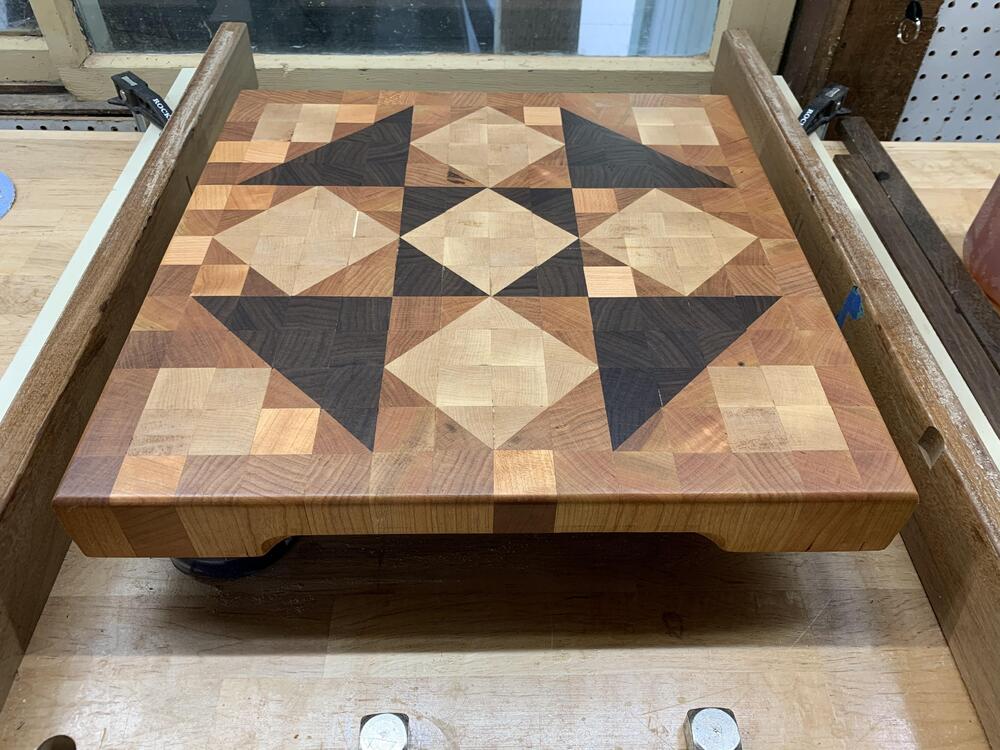
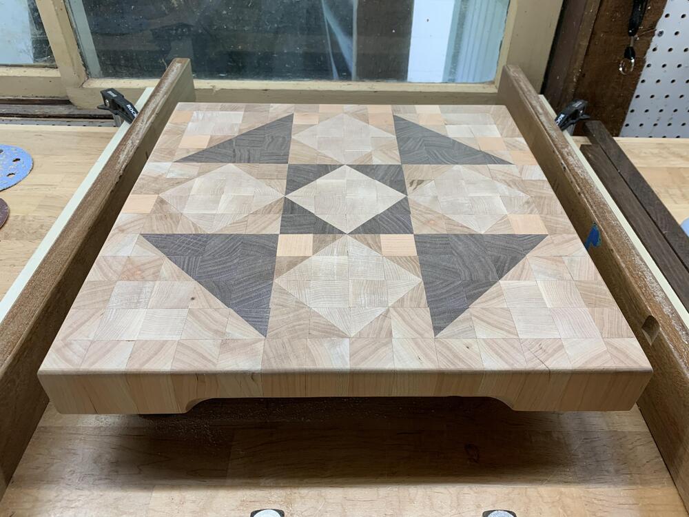
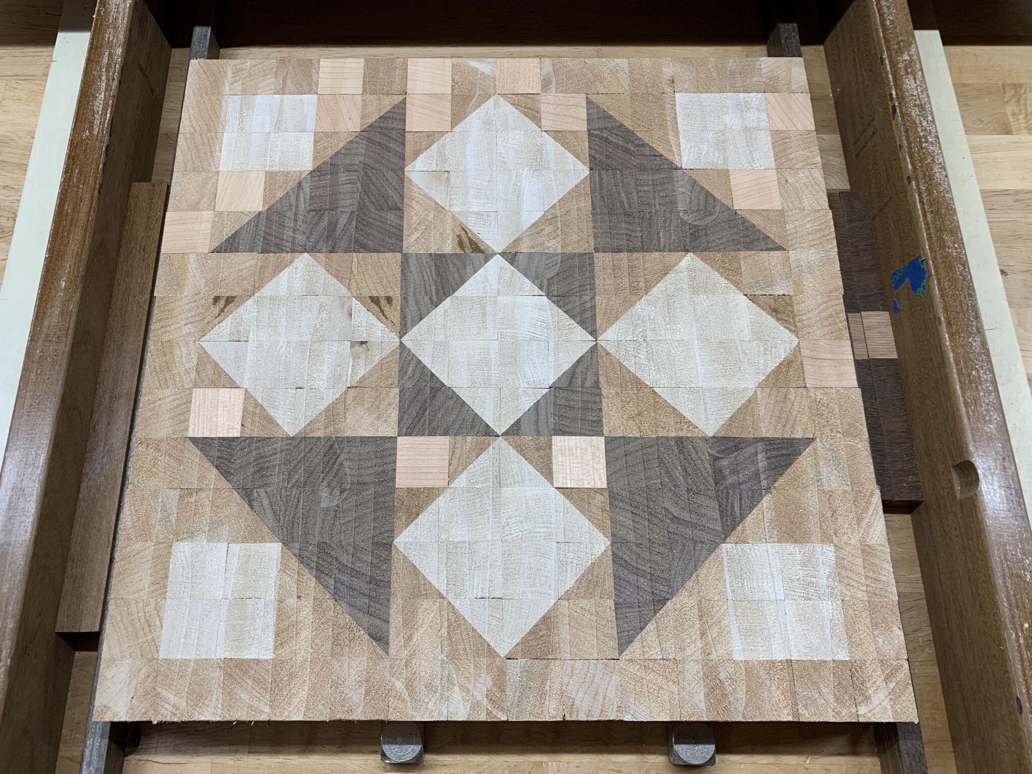
17 pointsDelivered this cutting board to my sister who is a lifelong quilter. *snip*
 17 points
 -
14 pointsGot the Brooklyn Bridge this afternoon. Still have a ton to figure out, but just listening to HiRes via Qobuz on old Emotiva power monitors I would say it is a hell of a DAC. Shilling will begin soon with an unboxing video. Stay tuned.14 points
-
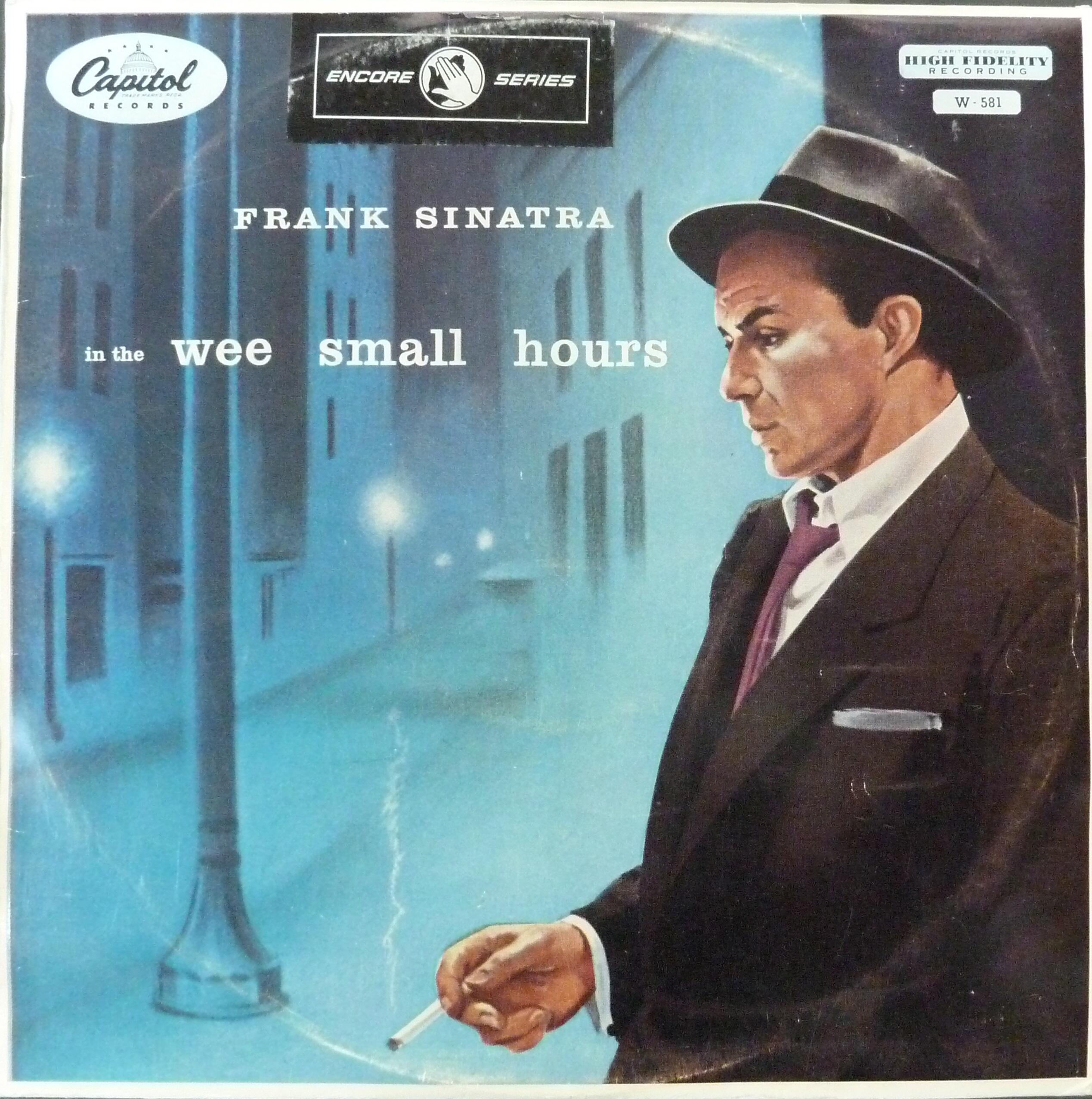
Plays to the strength of the Cicadas, plus it is a great album for us old guys.

 6 points
 -
6 points
-
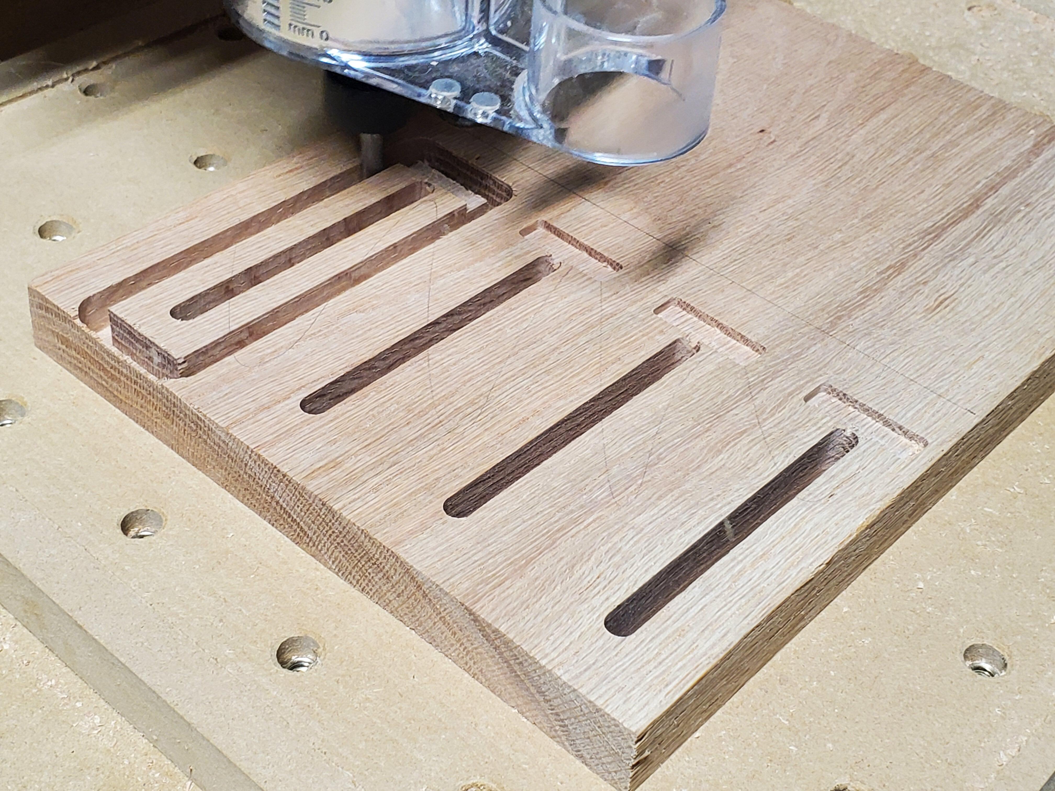
6 pointsMade some simple clamps for the Shapeoko out of some scrap red oak. Don't have a finished picture because I don't have a flush-trim router bit to cut off the tabs. Still learning feeds and speeds so the finish is also questionable.
 6 points
 -
5 pointsNicely done, Shelly! I'm still working thru brisket leftovers so breakfast was pretty fantastic this morning. Brisket, egg, and cheese on a grilled bagel.
 5 points
 -
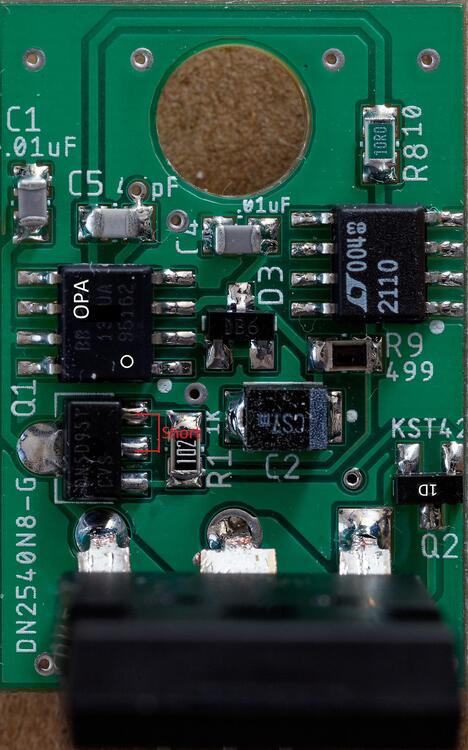
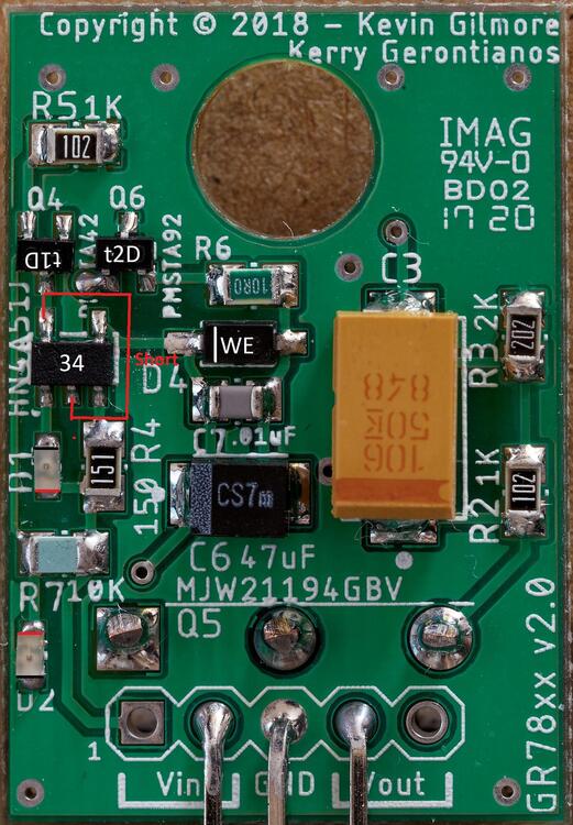
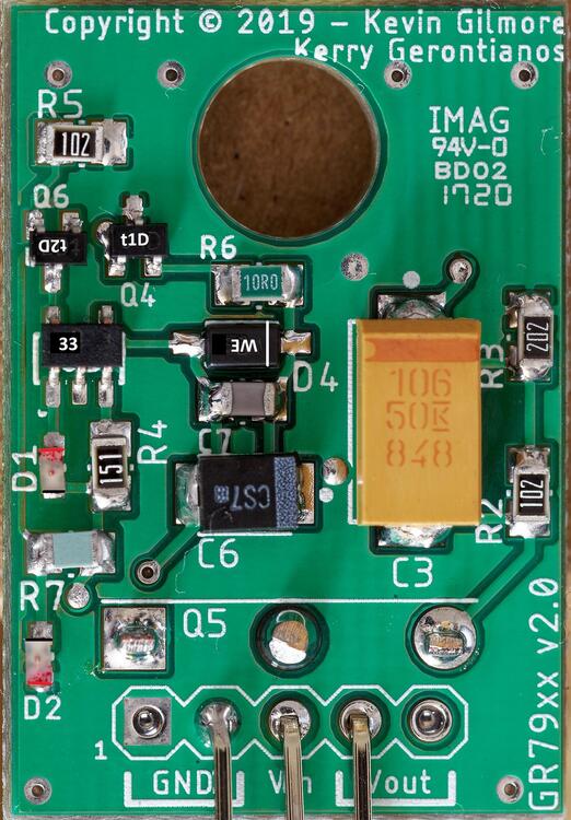
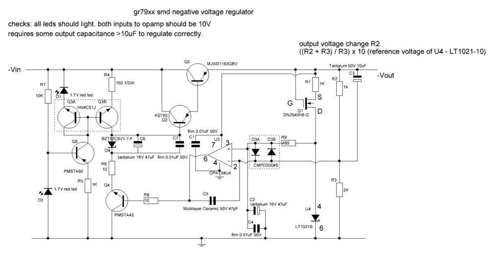
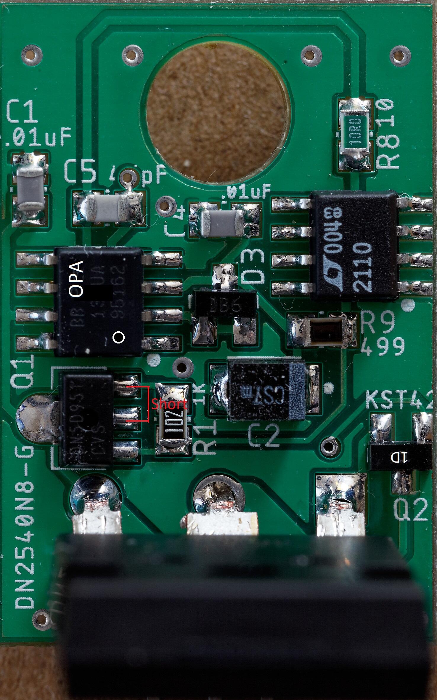
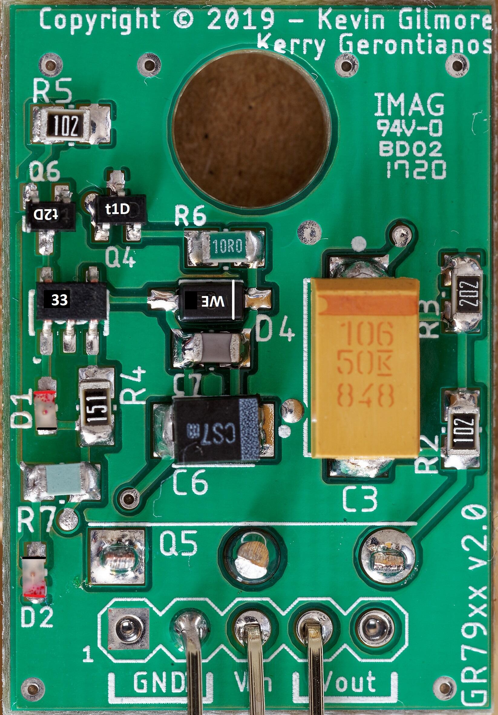
GR78xx build notes: Writing direction on the opamp and voltage reference match the writing direction on the pcb I suggest checking the led orientation with a multi-meter in diode test mode, finding out which way round the multi-meter leads need to be to make the diode light and then marking either the positive end of the led with a red pen or the negative with a black pen whilst holding the led with twisters - if you don't hold the led with twisters it has a nasty habit of sticking to the pen tip. The leds face opposite directions. Positive and negative ends are marked in the picture with red and black lines respectively. All transistors are shown with their case markings. Its a good idea to solder the leds in first and then check. D2 has the end closest to the Vin pins connected ground and so its easy to check its orientation is correct, the other led is opposite orientation. The DN2540 is a depletion device so if you measure resistance between pins, two of the pins will appear to be shorted - this is normal and shown on the picture. The tab is also electrically connected to the centre pin... The top left pin of the hn4a51j is also connected to the bottom middle pin on the ocb and will therefore also measure as a short. The pmsta devices have 3 digit case codes the first digit being the place of manufacture, the kst devices have two digit codes. Be aware Both the pmsta42 and kst42 have codes 1D but the pmsta42 has a t or other letter before the 1D for the manufacturing location. voltage ref should have 10V between pins 4 and 6 If you test the board by itself it must have capacitance connected to the output in excess of 20uF in order to regulate and not do strange things like increase the output voltage when the load increases. When setup for 15V output, input voltages bellow about 1.7V should result in very little current draw <1mA and no leds lit . At around 1.7V input D2 show glow dimly and increasing the input voltage should result in D2 glowing brighter, the current draw increasing and the output voltage increasing. When D2 is fully bright the current draw should be about 10mA. At about 17.5V input D1 should begin to light . Increasing the input voltage further will make D1 brighter and the current draw increase towards 10mA current the draw when the led is fully bright. At around 18.3V input the output should stabilise at around 15V and increasing the input voltage further should have no effect on the output voltage or current draw. The second 78xx I built required 0.2V more to regulate fully despite having a 8mV lower output. Load testing Expect approximately a 23mV decrease in output for each 100mA of load current drawn from the gr78xx. At 200mA the components on the board should be warm but easy to touch and leave your finger on. The MJW211 should also be a little warm. NOTE the metal tab of the MJW is live so don't short it to something. Voltage drop under load test, no heat-sinking, MJW211 close up against the pcb, 18.3V input. The drop in output voltage is the same using a 47uF output cap as 220uF. 100mA 23mV drop 200mA 46mV drop 300mA 69mV drop 400mA 93mV drop 500mA 116mV drop (note tab of mjw gets too hold to touch for more than a moment after a few minutes of this load. heat-sinking recommended) The second 78xx I built had voltage drops within 2mV of the first. The voltage drop under load is a bit more than a traditional 7815 to-220 voltage regulator under the same conditions. Removing the load results in the output voltage of the gr78xx going back to within 1mv of the original no load output almost instantly, even from the hot 500mA load. the voltage drop is fairly linear with load. Otuput voltage drift under constant load as the device heats up or cools down is very low. LED direction verification for gr78xx lower led D2 multimeter in diode check mode red probe on top of led black probe on bottom (as indicated in photo bellow) you should get about 0.89V drop led will not light. probes reversed meter should say OL upper led D1 multimeter in diode check mode black probe on top of led red probe on bottom (as indicated in photo bellow) you should get about 1.66V drop led will light. probes reversed meter should say OL 79xx build notes All polar caps, Zener and LEDs are in the opposite orientation to the 78xx, All resistors are in more or less the same positions and orientations as the 78xx, all transistors that are xx42xx become xx92xx and visa versa. NOTE in the BOM Q6 and Q4 appear to be the same on both the 78xx and 79xx however, on the silk screen the physical positions of Q4 and Q6 swapped in all other cases the transistors change in the BOM rather than the silkscreen designations moving. The opamp and LT voltage reference are in the same orientation as the 78xx. The HN4A51J becomes HN4C51J and the MJW211 changes from 94 to 93. All positions that hold a KST device continue to do so and the same is true for the PMSTA. Only the type of device swaps from NPN or PNP i.e. from kst42 to kst92 and visa versa or pmsta42 to pmsa92 and visa versa. The 79xx has similar load behaviour to the 78xx. LED direction verification for gr79xx lower led D2 multimeter in diode check mode red probe on bottom of led black probe on top (as indicated in photo bellow) you should get about 0.89V drop led will not light. probes reversed meter should say OL upper led D1 multimeter in diode check mode black probe on bottom of led red probe on top (as indicated in photo bellow) you should get about 1.66V drop led will light. probes reversed meter should say OL


 4 points
 -
Best Coast - Always Tomorrow I’m a big fan of these guys. Love the lo fi, surf pop sound. Pixies vibes.3 points
-
2 pointsAt least with Roon you send it over the network, so some of the USB issues are bypassed. And, now there's THIS, which I am thinking very much of getting.... (EDIT) just got, from Justin!2 points
-
2 pointsI've had good results using the old subwoofer/listening spot trick. Put your sub at your normal listening spot, put on some music with lots of info below 100hz and move around the room listening for the most balanced bass. Where it sounds best is a good place to place the sub.2 points
-
2 points
-
2 points
-
Iceland w/o tourists: https://i.imgur.com/tiyqM9Y.gifv2 points
-
2 pointsJim. I've always read that placement of the subwoofer isn't that critical. I myself have found this to be wrong. I'd say play around with placement, crossover frequency and level. I've had several systems with subs, and have usually found that in the case of front firing subs, lining up the the driver with my monitors has produced a more aligned and natural sound. Room corner placement can help with A/V systems, but IMO is too wooley for music only systems. In general a sealed sub is better for music as well. As Bryan stated, I think the "more is better" idea grabs you at first, because you're hearing all this bass you've been missing, but I think eventually you'll find yourself setting the crossover higher, and the level lower. Every room/system is different, and it's not a quick dial in, but keep playing around and you'll get there.2 points
-
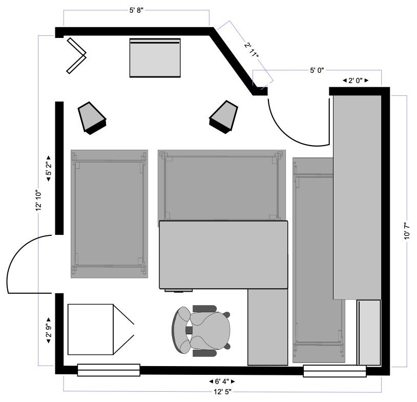
2 points2 pointsThinking of adding a REL T/5i subwoofer to flesh out the bottom end of the Moth Cicadas. This will be for stereo playback only, no HT, in a small room (146 cu ft). Anyone, have any experience integrating a sub with the Moths? Or with the REL subwoofer?1 point1 point1 point1 point1 pointMay I suggest moving the build notes and related discussions to the build thread?1 pointYeah, if you have the freedom to move the sub closer or farther away, that’s the same thing as continuous phase on the Sunfire.1 point1 pointAll good information and I agree with all of it. I plan to spend a lot of time tweaking the sub placement, crossover point and level. I have a copy of the Stereophile review of the Cicadas which has a nice set of measurements to start from. I wish the sub had a continuous phase adjustment but it just has a switch, a minor quibble. I am still trying to decide if I want to go with the T/5i (Down firing 10” woofer) or the T/7i (10” front firing woofer and 12” down firing passive radiator). Not a huge difference in either price or size between them. I have always liked the REL approach to subwoofer design, especially for stereo uses so I will likely go that route since I should just try them. I am just not sure which one will work better as I have relatively little room to move things around much as you can see in the floor plan below.
 1 point1 point1 point1 point1 point1 point1 point1 point1 pointNice! Pro Tip: If you have it attached via USB to a computer the Mytek Control Panel makes it much easier to change settings and do firmware upgrades. I use network streaming on mine for music playback but I have the Mac-mini attached via USB so I can use the control panel.1 point1 pointShelly, I'm planning something similar, just likely out of wood to accent the grill. If I get the manufacturing time down I'll make you a cutting board for your Traeger. Al, That cutting board is gorgeous, well done!1 point1 pointWe saw Hugh Bonneville, post Downton, in a play in the Chichester Festival Theatre. In Ibsen's An Enemy of the People. He was excellent.1 point1 pointslow n low... Traeger's are a very convenient way to enjoy BBQ. Nicely done! HS1 point1 pointNope, I tend to prefer everything if it's less American and more English/British but hate Downton Abbey. There has to be at least one more level of qualification that I'm missing. White slavery?1 pointI have a REL R-205 sub that looks like a similar size. I use it for HT duty with Gallo wall speakers. I haven't tried it with the Cicadas and very little with music but I think it would be a good fit with the Cicadas. It isn't slow and bloated from what I can tell. Makes me want to try it with the Cicadas now, although I would have to use the tape out on the Moth passive pre.1 pointThank you for the quick reply You are absolutely right about the output capacitance. I recreated the golden ref through hole output cap setup of a 220uF and 4.7uF in parallel and that did the trick. D1 now slowly comes on when the input goes above 17.5v and behaves much more like the golden reference through hole and the gr78xx is now happily regulating at 15.014V with no load. At 18.26v the output is now 15.015v. 50mA load the output is down from 15.015v to 15.003V, 100mA output is 14.991V, 200mA output is 14.967V all with 18.26v input and no heatsinking. Switching off the 200mA load the output is straight back to 15.015V. Playing around a little more regulation works with just the 4.7uF film cap on one of the two boards but results in the other board increasing the output voltage with increasing load! putting back the 220uF caps makes the second board behave like the first with similar voltage drops with increasing current draw. The silkscreen for the gr78xx says hn4a51j which is a pnp part which is consistent with the through hole golden ref which uses 2x ksp92ta which is also a pnp transistor... now if i could get more voltage references I could build the gr79xx boards....1 pointBTW Jim, have you considered this? https://www.monoprice.com/product?p_id=35143 There's a 12" version too. Also... https://www.audiogon.com/listings/lisa2ebg-monolith-by-monoprice-thx-certified-sealed-500-watt-powered-subwoofer-m10-s-subwoofers1 pointI did successfully build both GR78 and GR79 using the GB boards. First of all, you need some capacitance on the output for the regulators to work. That's the first thing I would try. I did have an issue with GR78 at first and finally figured out I used the wrong part (used HN4A51J instead of HN4C51J). But try adding some capacitance on the output ends first.1 pointDonald Brinegar Singers, Celebration Collection Yes, really. The lead singer of Al1ce shared privately with me that she sings on here, so I gave it a serious listen and it's so peaceful and soothing and perfectly sung I can't help but love it.
 1 point1 pointNot with either of those two, but when I first discovered audiophile equipment, I ran my Spendor S3/5a speakers with a small Jolida integrated amp and a Sunfire Subwoofer. A couple lessons learned, but the biggest one is the difference between longer cable runs (the sub's crossover can relieve whatever amp is driving the Cicadas from having to amplify those lower frequencies) vs having a less accurate crossover point (the Cicadas probably have a lower frequency roll off that can be -- very roughly -- matched with the sub's crossover), so spend some time researching both. The Sunfire had a nice feature called "variable phase" which basically adjusted microdelay. It definitely made integrating easier. Also, where the crossover point is very important -- the lower the better.1 pointi have been using a sub with my Alerions for four or five years. i copied Mike’s choice of an HSU Research STF-2 (he used/may still use with his Cicadas). it is ported but never seems out of time alignment (no “speed” issue i’ve heard about for some ported). i originally had the crossover set lower, maybe 50-60hz, but in the last year ramped it up to 80-100hz and noticed an improvement in the low end integrating into overall presentation (i continue to change my volume setting on the sub probably once a month, never feel like i have it right). in my current speaker positioning, the sub location has mostly disappeared but not entirely. that’s been my main issue and recently i have been thinking about making a switch to a more mid-tier sealed sub myself... either from HSU (ULS-15 MK2) or SVS. the REL you linked looks like another comparable option. my room is also pretty small, you definitely don’t need to push a ton of SPL from the low-end to get a dramatically fuller sound from these full range speakers. knowing both your speakers and your power amp... basically i recommend you go for it and it will make a huge difference and most importantly allow the lowther drivers to focus on what they do best... mid range glory. it is going to feel like something you should have done years ago. that’s certainly how i felt.1 point1 pointGetting ready to reheat for dinner but early snacking is promising.
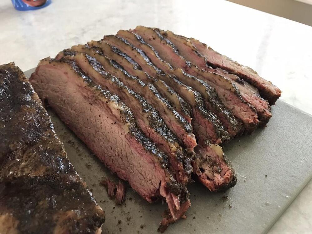 1 point1 pointThe brisket finished crazy fast after I wrapped so clearly the cook times on the Traeger are going to be quite a bit different than the electric smoker. Not too concerned about it being done early, I'll just have to check the internal temp about an hour before dinner and reheat as needed. Felt super tender to the probe so here's to hoping I got this one right.1 pointFinally completed the dynahi. I really enjoyed this DIY processing. Based on previous experience, this time I spent more time on selecting parts and adjustment, also increased heat sink size, quiescent current increased to 75mA. The gain keeps the original design value (200K/10K) and there is no background noise even using high efficiency earphones. Thank you everyone for your experience and information on this thread.1 point0 points0 pointsPatrick Poivey, French voice of Bruce Willis, Tom Cruise, Kyle MacLachlan, Charlie Sheen, Spike Lee, Don Johnson, and Mickey Rourke, dies at 72 https://www.theguardian.com/world/2020/jun/17/patrick-poivey-french-voice-of-bruce-willis-dies-at-72?CMP=Share_iOSApp_Other0 points


Important Information
By using this site, you agree to our Terms of Use.
Account
Navigation
Search
Configure browser push notifications
Chrome (Android)
- Tap the lock icon next to the address bar.
- Tap Permissions → Notifications.
- Adjust your preference.
Chrome (Desktop)
- Click the padlock icon in the address bar.
- Select Site settings.
- Find Notifications and adjust your preference.
Safari (iOS 16.4+)
- Ensure the site is installed via Add to Home Screen.
- Open Settings App → Notifications.
- Find your app name and adjust your preference.
Safari (macOS)
- Go to Safari → Preferences.
- Click the Websites tab.
- Select Notifications in the sidebar.
- Find this website and adjust your preference.
Edge (Android)
- Tap the lock icon next to the address bar.
- Tap Permissions.
- Find Notifications and adjust your preference.
Edge (Desktop)
- Click the padlock icon in the address bar.
- Click Permissions for this site.
- Find Notifications and adjust your preference.
Firefox (Android)
- Go to Settings → Site permissions.
- Tap Notifications.
- Find this site in the list and adjust your preference.
Firefox (Desktop)
- Open Firefox Settings.
- Search for Notifications.
- Find this site in the list and adjust your preference.