

Leaderboard
-
swt61
High Rollers31Points22241Posts -
Hopstretch
High Rollers26Points16779Posts -
Voltron
High Rollers18Points34514Posts -
skullguise
High Rollers14Points8865Posts


Popular Content
Showing content with the highest reputation on 10/03/20 in all areas
-
8 pointsFor anyone still interested, the MSI came in yesterday. To Nate's point, I probably did overbuy. But my overall thought was to get something that will last me, as I keep my home PC around 7+ years on average. So I wanted to max-out the stock configuration (processor, RAM, SSD HD) within a reasonable budget, as access to the innards of laptops for future upgrades gets more difficult with each new model. Off-grid battery life is less of a consideration, as this will be pretty stationary in my home office & won't be taken on travels (an old Android tablet and/or my cellphone serve that purpose sufficiently). Legacy ports were important to keep things simple for older peripherals & hardwired network connectivity. Buying through Costco leverages the kickback I get at the end of the membership year, as well as their stellar customer service should anything go awry. Having the MSI go on-sale this month was the tipping point. I fired it up last night & applied the outstanding Windows OS updates. That took much longer than updating my wife's Macbook when she got it a few months back. Now to transfer my files & install applications. TL;DR - seems pretty good for basically a fast Windows PC. #fingerscrossed Thanks again all for your inputs to my query.8 points
-
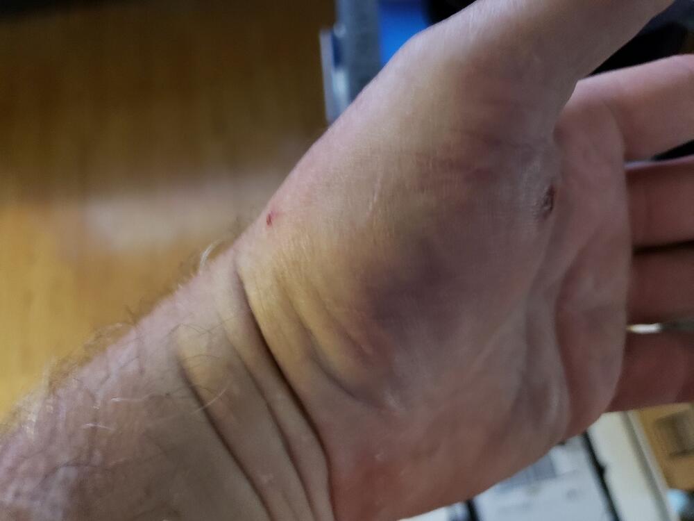
4 pointsI'm happy to see that I'm still a fast healer. I can count the number of times I've ever had a wound become infected on two fingers. Still slightly sore, but fully functioning. Really just tender when I press directly on the wound. My body makes up in healing what my brain lacks in intelligence.
 4 points
 -
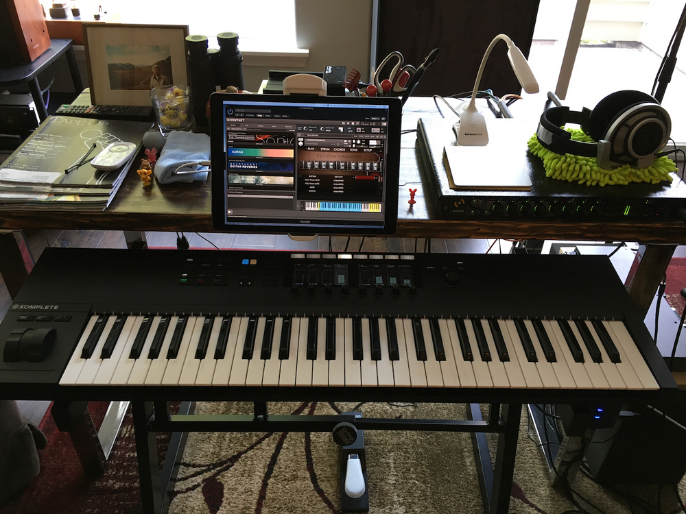
3 points2 pointsYum. Kinda like candy or junk food, I can’t take it all the time, but every once in a while, I do enjoy London Grammar.2 points2 pointsI read on a Microsoft programmer forum that the flight simulator was designed to mimic what life would be like in 2020.2 points2 pointsAfter a month and a half, I never could make the connection with the Arturia Keylab Mk ll. I love the build quality and the integration as a synth but my fingers just never loved it. So I've had the NI S61 for a couple of days now and I think (hoping) it's going to make the cut. I used my Impulse every day for more than 8 years so I live with these things for the long haul.
 2 pointsHeard this on the way home the other night and it struck a nerve.2 points1 pointMilla Jovovich answers fans questions in an online chat on AOL, February 13, 1995. ISS crossing in front of NEOWISE. Once-in-a-lifetime shot. Bo Diddley and Chuck Berry jamming at Madison Square Garden. New York, 1972.1 point1 pointI never owned a real piano so I learned (what little I learned) on electrics. So, I don't really like fully weighted (hammer action) keyboards. The Fatar keybed on the S61 is semi weighted and it's a little heavier than the Arturia. There are a number of Fatar keybed models. Some are fully weighted and are used with wooden keys on some of the best electric pianos. In fact, as far as the "effort" need, I prefer the Arturia a tiny bit more than the S61. It's the keys themselves that I like on the S61. The Arturia has a lot of things about it that I prefer; The build is better I much prefer the faders vs the rotary encoders The software package is better About $280 cheaper The things I like about the S61 The keys themselves (although I can imagine that I'll prefer the Fatar keybed after I get used to the extra strength needed) The integration with Logic with the larger screen real estate I'll probably put the KeyLab on Reverb soon.1 point1 pointTwo things: register it right away! They only give you 30 days. Even if you go through CostCo, you don’t want to rule that out as an option. That’s the mistake I made and vowed to never make again. Also, yes, still interested, so please do report back if things change. Decided to remain ultra frugal (or, “turboskint“) for now, but still following since I have similar priorities.1 point1 pointI know gaming headphones aren't the goal of the thread, but I've been spending quite a bit of time with them lately. To play DCS and IL II (military flight simulators) and to have business teleconferences I needed a headset with mix and bought a Logitec G432 a couple of weeks ago. It does not reach the level of most headphones that I have at home (obviously) but they do their job quite well in games and I can "listen to music" while I work without worrying about whether they fall or suffer a blow, etc ... I do not know how long the coating will last of the earpads but in general I think he is quite well built. One detail that I really liked is the is the DAC that comes with them because it´s very useful since you can convert any 3.5-jack headset to USB. I think it was about 50 bucks well spent.1 pointThe required wattage for the bias trimpots can be calculated easily. For the trimpots, the current is approximately 10 mA (approximately 5 mA per tube section), and the resistance is 2 kilohms, so the maximum power through them is I*I*R = (.01)*(.01)*2k = 0.2 watts. Using the rule of thirds, this means that any trimpot that is rated at 0.6 watts or more is fine.1 point1 pointwas that straight through with a nail? opened a fat sack from mouser
 1 pointwhen I changed the caps on my T1 (not T1S), I remember the original caps did not have the leads symmetrically center oriented like the caps they make nowadays (Weird). Because of this, I needed caps with a smaller diameter than the original for them to all fit in together.1 pointYup!1 pointBest of Mac Davis Fun tunes, but some of these lyrics sound a little different in 2020. "She'll resist. Then she'll surrender."
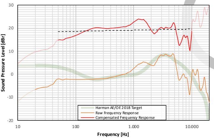
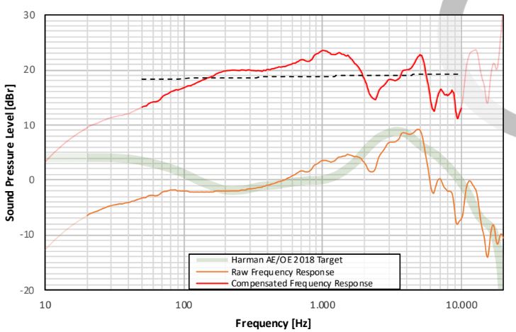
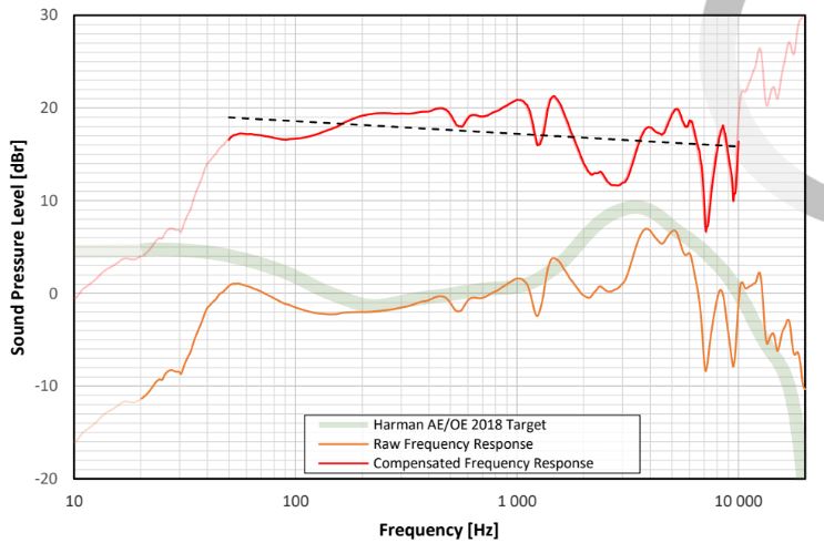
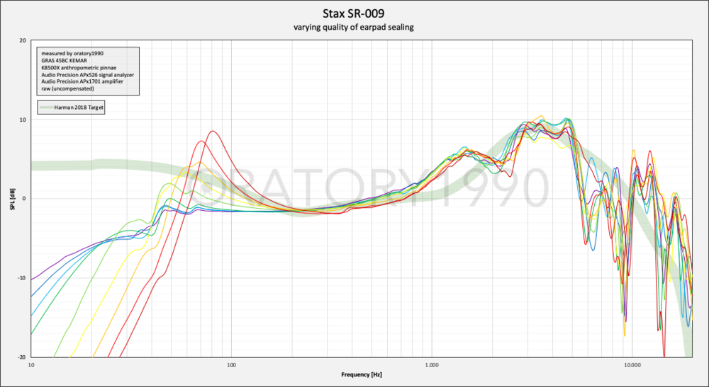
 1 point1 pointI’m a huge fan, thanks for posting. Yes, the influx of “shredders” is his fault, from when he was teaching, but he has a musicality that most of his alumni do not.1 point1 pointRick just released an interview with Joe Satriani. I was never a fan of his but he has some great stuff to say about music and being a musician.1 point1 point1 pointHad a Vodavi phone system at work that one of the station ports didn't work. Normally I wouldn't even bother trying a repair on one of these and just replace the unit, but lacking any working ones on the shelf, I decided to have a go at it... and somehow actually managed to fix it. 😲 Random picture of one off the internet for reference: I had to replace one of those little blue transformers, the thermistor beside it, and some smd components on the back of the board, with ones I salvaged off a different broken unit. It took a few passes to track down everything that was damaged, but now it works as it should. Yay.1 point1 pointSame as above, but in picture format: SR-007 Mk1 SR-007 Mk2.9 Blu tack SR-009 SR-009S Here is how the SR-009 reacts to having a bad seal on the sides of your head (and thus 009S as well). Again, thanks to oratory1990 for his detailed testing.
 1 point1 pointBlue hawaii build notes based on kgbhver6sbipolarinc. The amp board is fairly easy to build, but I do have a few observations 1. EITHER populate the LSK389 6 pin dual transistor OR the two single transistors each side NOT both EITHER populate the STN9360 smd transistors OR the KSA1156 just below them NOT both important and high voltage tracks run close to the screw holes for attaching the heatsink L brackets to the board on the top side of the pcb. I would be very wary about placing the L bracket on this side, if the solder mask is rubbed there will be a short to the L bracket which is probably electrically connected to the rest of the case and the case is probably connected to earth (certainly in countries with 3 pin mains leads) and that’s going to be bad.... 2. the tube sockets and trim pots go on the other side of the pcb to the rest of the components. If you want you can also put the leds on the top side so you can see what is going on. The 3 leds will give you an indirect indication of the status of the board. All 3 leds should be lit for normal operation. The led by itself gives an indication of the -400V line, the two leds closer together indirectly show the state of the +-15VDc lines. There is no led for the +400V line. 3. to set the constant current to 20mA you need to measure 1V DC across the 50ohm resistor near the trimpot (one for each valve). Since the trim pot is on the top side of the pcb it makes sense to put the 50ohm resistor on the top side two. I raised the resistor off the circuit board so I could easily clip insulated multimeter probes to the leads. 4. I found mounting the screw terminals to the underside was a pain in the ****. it may look neater BUT to screw the terminals you have to get to the underside of the board. BUT the pcb is mounted to an L bracket mounted to a large heatsink. So, you either have to flip the entire thing over.... hope you have long enough wires to allow this OR put the entire thing on a desk and stand on your head and screw upwards from below.... I am sorely tempted to desolder the screw terminals and mount them on the top of the pcb. 5. if you are going to have a single ended input to the amp e.g. RCA/phono then the -input should be connected to the ground for minimal hum. 6. when you are doing the inter board wiring for the first time make sure the inputs are shorted to ground. I got some instability issues because my input wiring was too close to either the stax output socket wiring or the main transformer and had nothing connected to it and was not shorted to ground. 7 when you build the amps boards set all the trim pots for halfway and verify with a multimeter in ohms mode. This will save you from having a trimpot at one extreme of its travel and result in LARGE DC offsets or high constant current pull.... 8. if you have a scope or two multimeters it’s much easier to set up the amp because changing the DC offset also makes the balance change and vice versa. With a 2-channel scope or 2 meters its far easier to chase the correct spot. Adjust the two trim pots near the 50ohm resistors have been adjusted for 1V across the resistor i.e. 20mA current, first. Next you can adjust the dc offset and balance between the valves, the audio inputs should be shorted to ground and no headphones attached for all setup. If you are using a scope make sure it’s set to DC coupling... AC coupling will ignore any DC offset and its DC offset we are trying to null out. Also, if you have a scope do no connect the ground terminals of the probes to anything only the centre pin of the probes is needed. (almost all scopes internally are grounded via the main input) almost all multimeters are NOT and require the ground lead connecting to the amp board or psu ground. 9. Im my experience if you are building a single box amp, even if the transformer has a magnetic shield foil, putting the audio input wires anywhere near the transformer will result in hummmmmmm..... the magnetic field is STRONG with this one... 10 The hottest transistors on the blue hawaii are the FQPF8N80Cs, measuring the mounting screw of the transistor - (which seems to be the hottest part I can find) I get a stable 65C after multiple hours of use, this is using arctic ceramique thermal paste, aluminium L bracket 200mm by 80mm heatsink with 40mm fins and aluminium oxide insulation pads.... 20mA constant current and +-400VDC B-+ 11. double check which trimpot you are adjusting. I have adjusted the constant current trimpots by accident when trying to do DC offset and balance multiple times.... 12 some labelling of the trimpots to say what does what on the silkscreen would be nice... 13 labelling the screw terminals on the top side of the board would be nice for checking wiring after the boards are in place. I hope this is useful James1 point1 pointBlue hawaii build notes for the kgsshvpssicfetdual2new PSU The kgsshvpssicfetdual2new is based on version 1.6 of the kgsshv psu single boards and does NOT have the cpc1117N or resistor required for simple B+,B- delayed start. (it’s still possible to implement delayed start but it requires a relay(s) which the cpc1117N avoids). In all other ways its similar to the v1.7 single boards. The single boards put the b+ on one board and the b- on another and split the -+15V and bias between them. The kgsshv ps dual has all the dc voltages required to power the blue hawaii and apart from the notes above is topologically and componentry identical to the single psu boards. The notes bellow applies to BOTH the single and the dual psu boards. Construction is straightforward other than 1. the silkscreen shows 15-0-15VAC input for the + and 15VDC outputs, Since the -+15V output is a simple DC supply with a bridge rectifier and voltage regulators 15-0-15VAC is NOT sufficient to provide -+15V output... I have verified this using a variac. There is about 0.6V drop across each diode in the bridge *plus* the voltage regs need between 1V and 1.5V more input DC than their output in order to regulate properly. so 18-0-18AC is actually required to get a properly regulated -+15VDC output... Any more VAC input will be converted into heat by the voltage regs. However, with 18VAC-0-18VAC centre tapped input the voltage regs run very cool with the small heatsink they are bolted to. 2. the blue hawaii amp boards -400VDC lines draw more current than the +400V lines. If you connect a single channel up to the psu board for testing there will be no problems. Connecting two channels results in the -400V line on the psu going into current limit and the voltage dropping to (im my case) about -175VDC. The fix is fortunately easy. The 5.1ohm 3W or 5W resistors are the current sense resistors for the over current protection. On the -400V psu side either replace the 5.1ohm resistor with about 2.6ohm or similar wattage and type or parallel another identical 5.1ohm around the existing one. The +400V does not need modification. the lower the resistors value the more current supplied before the current limit cicruit activates. I don’t have anyway to variable load a line that has such a high voltage but I would guesstimate that the 5.1ohm resistor current limits at about 100mA since two amp boards +400V together draw around 81mA and there is no problem with 5.1ohm and 2 -400V boards draw between them around 129mA and that causes current limiting with 5.1ohm sense resistors. 3 make sure none of the metals tabs on the transistors are shorted to the heatsink/L bracket that mounts to the heatsink. Use electrically insulated spacers between the back of the transistors with metal tabs and the L bracket/heatsink AND use a nonconductive gromet to insulate the bolt from the transistor. The psu transistors do not get that hot with a reasonable size heatsink attached. 4. if you are building in a u2 high case the largest main psu caps you can put in are Kemet 500V 470uF long life at 65mm tall. Beware they also do an 80mm tall 470uF cap - this will NOT fit in 2u. Similarly 680uF caps at 500V are 80mm high and will not fit. 5. if you want to check the bias is 580V use the bias test point. Dont measure at the bias screw terminal. Why, typical multimeters have a 10M ohm input impedance and assume whatever they are measuring across is much less than 10Mohm... this is NOT the case for the bias line which has a 4.7Mohm resistor. result the multimeter will NOT give the correct voltage reading between the ground screw and the bias screw. Measure from the bias pad nearby to the ground screw. Also, don’t measure the bias with headphones attached. 6. there is only one screw terminal for +400V, -400V, +15V and -15V so you will need to connect two wires to each screw terminal. This limits the gauge of the wire. Also make sure you are screwed the terminal down well, its easy to have one wire firmly affixed and the other one lose.... 7. to adjust the B+ and B- lines the two 390K resistors (R8 and R9) in series with the 20K resistor (R7) just after the 1N007 diode that have the 0.047uF cap across them need to be changed. Approximately (for my psu) I got the following 442K for 450VDC (note requires a transformer with 360VAC output to have enough voltage input to get proper regulation) 390K for 404VDC (transformer 330VAC or more output) 365K for 375VDC (transformer 310VAC or more output) the approximate equation for me was the total of the 2 resistors in ohms/(20,000-700)*10 (the 20,000 is the resistor in series with the resistors you are changing, the 10 is the output of the voltage reference LT1021-10), the 700 is the fudge factor to make the numbers accurate for me... (variation in voltage reference, variation in the 20K resistor etc etc...) 8. To test for proper regulation connect a volt meter to the nominally +-400V output and a ground screw terminal and either power the transformer from a variac OR if your variac can go high enough you could go from the variac output into the 300VAC input of the psu. There is no need to have amp boards connected at all and its safer if you dont. Slowly increase the AC and you should see the DC output rise. At some point increasing the variac by some volts will result in very small output increases (in the order of few milli volts) now the psu is regulating. Measure the 330VAC input of the psu and that’s the minimum transformer output voltage you need for regulation. Both the + and - 400V sides of the psu should have similarly behaviour and similar minimum VAC input requirements since they are almost identical in topology and are identical in components. 9. I would recommend initially testing the psu board without amp boards connected in case voltages are way off. However, with no load on the psu the b+ and b- lines, they will take some minutes to fall to 0v and with no headphones the bias line will stay high for a long time. Fortunately the bias line can be discharged just by connecting a multimeter to it and ground and set to DC volts. Even a meter with 10Mohm input impedance will drain the bias line in a few minutes. the -+15V lines will be drained by the voltage regulators. 10 I would recommend a variac for initial testing it allows you to bring voltages up slowly and make sure that voltages are going up in symmetry (-+400V, -+15V) and becoming stable. 11. If the outputs look good with no amp boards attached, connect one board and repeat the tests. Better to put in channel in danger than both... especially if the amp boards have not been tested. 12. if test with the other amp board only. You don’t want to blame the psu if one amp board only is miss behaving... 13. test with both amp boards. Remember if the -400V line goes down in voltage significantly only with 2 amp boards attached and is fine with one you probably have a current limit problem and did not implement item 2 here! 14 don’t plug in headphones unless 1. you have a spare pair you don’t mind frying. 2. you have tested voltages, dc offsets are nulled and you are happy. ideally look at the outputs on a scope and put some sine waves in.... 15 Before you plug in anything visually inspect for solder bridges... I had a partial bridge it only started conducting when the input AC to the psu went above about 26VAC... thank you variac... 16 use probes with insulation, there is lots of high voltages don’t short out things with you probes.... 17 Before you power up anything double check the wiring the - and + on the silkscreen are quite small and you dont want +400V going to a place expecting -400V.... 18 temperatures are low, with the psu attached at a 200mm by 80mm heatsink with 40mm fins, (both amp boards running constant current 20mA and -+400V B-+), the centre of the case of the +400V side transistors are about 40C, the -400V transistors are around 3C higher at around 43C. The cases on the C2M1000170D transistors take some time to become as hot as the mounting screws. The 10M90S cases reach the mounting screw temperatures far faster. 19 I know the board has been made as small as possible and around the screw terminals its rather crowded. But it would be nice if there was sepertate screw terminals for the -+400V and -+15V for each channel, this would allow for the use of thicker wires and reduce the possibility of a wire comming out. (I have already had the situation where I though both wires where screwed in tightly to a single terminal and then one came out) Hope this is useful James1 point1 pointFor anyone building a blue hawaii, here are the current draws for my build after 5 minutes of power on, rounded up to the nearest mA. These figures provide no margin for variation, to headroom for inrush on power up and should not be considered minimum specs for the transformer... PSU board set to 400V output (actual around 404V) constant current on the amp boards set to 20mA per valve inputs shorted to ground no headphones attached groove tubes el34 kemet long life 470uF caps @ 550V for B+ and B- Boards used: amp Blue Hawaii kgbhver6sbipolarinc PSU kgsshvpssicfetdual2new (single board version 1.6 with no delayed start cpc1117n that appeared in ver 1.7)total for both channels: -15VDC line draws 10mA +15VDC line draws 11mA +400VDC line draws 81mA -400VDC line draws 128mA EACH 6.3VAC line draws 3.1A Primary side current draw 0.67A @230VAC All Measurements made on a Brymen bm869s multimeter. NOTE With @230V primary the inrush current is significant and will blow a 3A fast blow fuse on power up, and blow a 4A fast blow after half a dozen power ups (tested with no B+- delay circuit). With a delay circuit 3.15A Timed fuse looks good. transformer I used (which is overkill, but as a result the transformer generates very little heat. ) 330VAC 300mA 330Vac 300mA 36V AC centre tapped 200mA 18v-0-18v 6.3VAC 4.5A 6.3VAC 4.5A Now I have measurements I would say that the transformer could be scaled down to somthing like 330V 250mA 330V 150mA +18V centre tap -18V 50mA 2x 6.3V 4.5A I hope this post will help someone. regards James1 point0 points0 points0 pointsSome are more shocked than others. https://arstechnica.com/cars/2020/10/honda-shocks-f1-says-it-will-quit-the-sport-after-2021/0 points


Important Information
By using this site, you agree to our Terms of Use.