

Leaderboard


Popular Content
Showing content with the highest reputation on 11/11/23 in all areas
-
2 points
-
2 pointsThe DMV wasn't too sharp reviewing that vanity plate application!2 points
-
1 point
-
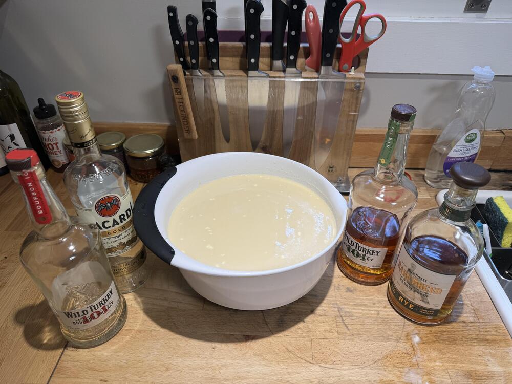
1 point1 point1 pointHappy birthday, ryeman! Thank you for being part of my inspiration in my quest to the deliciousness of rye. (party favour noise)1 point1 point1 point1 point1 point1 point1 point1 point1 pointHappy Birthday, Mikey! Something to accompany a curry (funny looking or not) (🍌 🥃)1 point1 point1 point1 point1 point1 point1 point1 point1 pointThis is an idea I've had for years. I have a lot of audio equipment and other gear (but still a tiny fraction compared to many HCers). Much of it is in less than 100% working order. Some of it is "door stop" or "paperweight" status. There are bits I'd like to get working again and things I'd do better to throw out. I am sure I am not the only one. In no particular order: HeadRoom Milllet(t) Hybrid serial #1. Pete's name misspelled on the front panel. Class A circuitry. I bought it from one HighLife 10 years ago. I strongly suspect it's got bad caps. This is among the top pieces of gear I wish to restore. It's got real history to it. Also it sounds amazing when it works. The logistics of repairing are complex. I have to find someone who is willing to work on it. I've looked at the HeadRoom site and I hardly recognize it these days. I get the strong impression that they do NOT service old HR gear (or even acknowledge that it exists.) After I find someone to fix the amp, I have to send it and the PSU to that person and wait however long. The problem is I only have one HeadRoom DPS, which is currently being used by my HR Balanced Desktop (now my most used headphone amp.) Tascam 122 Mk III. The greatest cassette deck ever made, full stop. Bests Revox and Nakamichi units. (Tapes recorded on a Nak and played back on another Nak might sound better, but that's a severely limited prospect.) Mine has at minimum bad belts and possibly a bad gear. A clever friend of mine bought one and restored it himself. He said it was nontrivial, but not impossible. A pair of Unisound AU265 speakers. Way back in 2010, a website with the silly name ThingFling listed these for $100 or $200 shipped They were like $1200 new in the 00s. One of mine rattles like a bastard when any amount of bass goes through it. I genuinely do not know if it's one of the drivers or an issue with the cabinet. I'd love to get this pair working again because the Unisounds look like proper pieces of furniture and are the big burly battered black boxes that my NS-1000s are: My (sainted, octogenarian) mother would much prefer the Unisounds to these things. The NS1Ks are so imposing that the contractor we had in the house to fix some electrical problems talked about the speakers almost as much as he did the actual work he had to do. I thought it was hilarious. My mother was less amused. Symetrix 528E voice processor. Not an audiophile thing at all. For a good 15 years it was THE preamp to mate with an Electro-Voice RE20 microphone for speech purposes. As someone who has spent entirely too long pontificating about ...all sorts of things on the mic, I love the combo. There's actually a company that refurbs and even improves 528Es as a cottage industry. I was going to pursue this route ...then covid hit and life got complicated. I still have plans to pick up that thread. Audio Research LS-9. Very solid preamp with mixed balanced and SE I/O. It's a totally solid state design, which is unusual for the manufacturer. I found it to be very neutral. Whatever I put into it came out of it the same. Mine has ...issues. One of the switches is missing a bat after a wire got caught on it. Also there's some internal problems. I suspect bad caps. TBH I should really restore this thing but I'm not sure I can be arsed any time quickly. It really is a great pre. California Audio Labs tube DAC. I bought it from an HCr years ago. It needed a new chip and a tube. This is trivially easy to do, but I felt like a big boy when I got it working. It was actually one of my favorite secondary DACs. It was great for lo-fi content like streaming audio. Unfortunately, I used some idiot Monster Cable interconnects on it and those things grip like their life defends on it. One the DAC's RCA jacks came out with the stupid cable and I have never attempted a fix. Canon EF-S 17-85mm F/4-5.6 IS USM. The "better" kit lens I got with my EOS 30D in the summer of 2006. I used it extensively until it stopped working after I took this shot in 2009: TBH I don't think I'd pay to fix it. It's crap at the wide end and I'm done with EF-S until further notice. Canon EF 35mm F/2. It's had a broken AF motor since 2009 when some idiot club goer knocked my lens on to the floor. I've used it as a manual focus lens for 14 years now. It's still a great lens. I'm probably going to buy the newish 35mm F/2 IS at some point. As I have said many times in the photo thread, 35mm F/2 is the best lens for APS-C or full frame in my estimation. That's all the broken kit I can think of off the top of my head. I'm sure there's more, both here and still on the mainland. So HC, what broken bits of kit are YOU avoiding dealing with today?1 point1 pointAlright, I'll bite on the Millet(t) since it was the amp that I reviewed years and years ago and actually owned for a little while after I bought it from Tyll. Full disclosure, I'd hope to repair it and return it to you Knucks.1 point1 pointEven Shelly drank year old Mattnog, despite her phobias! 😆 It's safe so long as it was refrigerated. Wild Turkey Mattnog 2023! And the Bacardi Gold ought to add some more sweetness given the two cups of rye.


 1 point1 pointIll Communication Beastie Boys 1994 https://album.link/i/724771323 Example: Yeah I know 'Sabotage' rules, but I just really like how much Jazz is on this album. Probably pissed a lot of people off back in the 90s, but I think that this is really a great complete album. Well done.
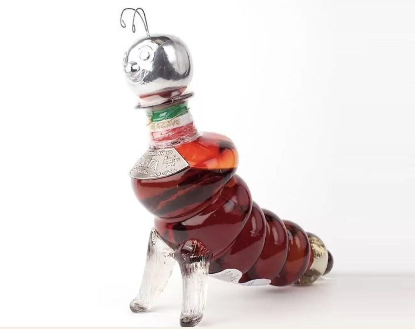
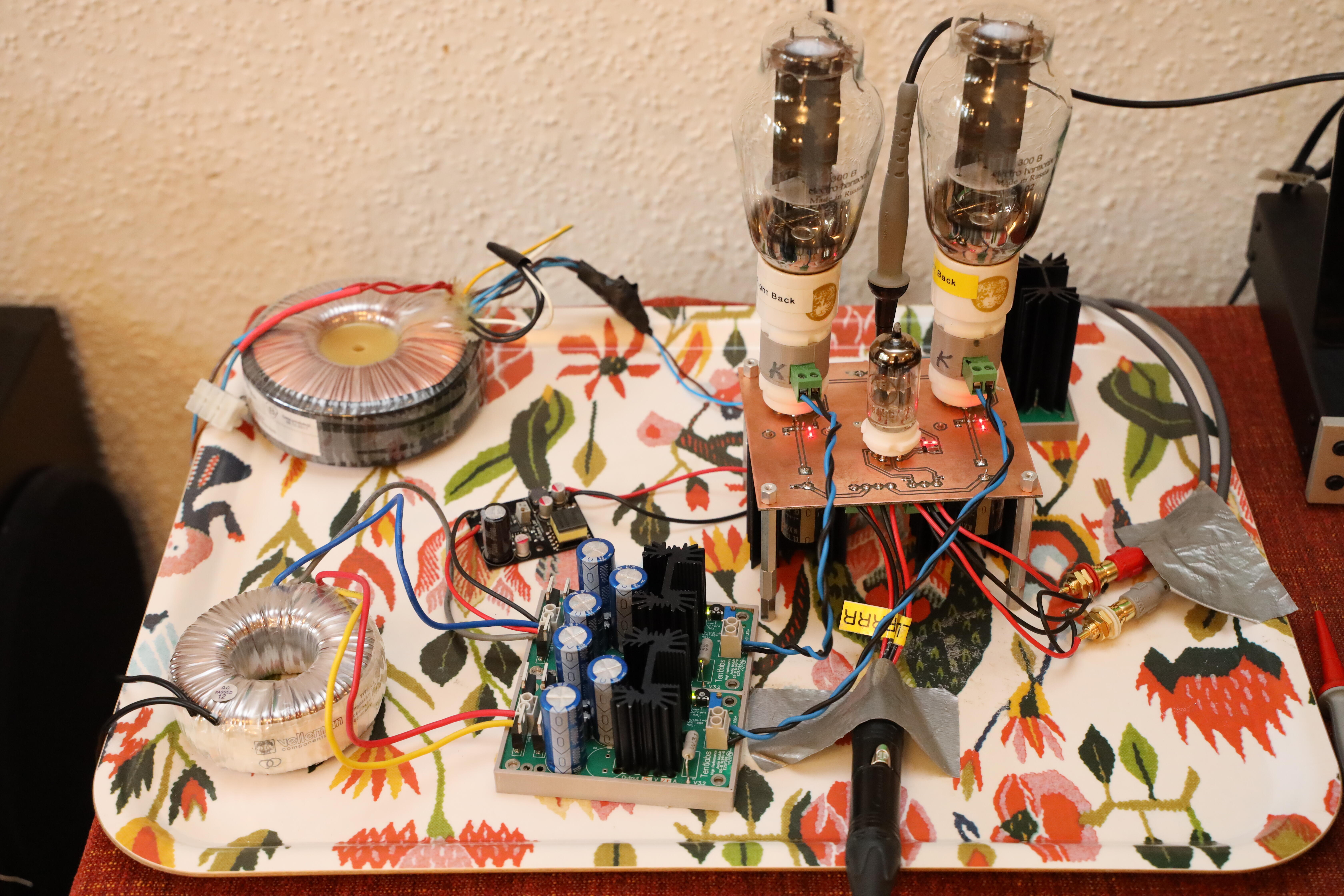
 1 point1 pointJadeDubbleBottle is served. One 6922, two 300B and a few components on amp pcb. All DC filaments and GRHV at 140V. No cats and children have moved out so, no rush with chassis.
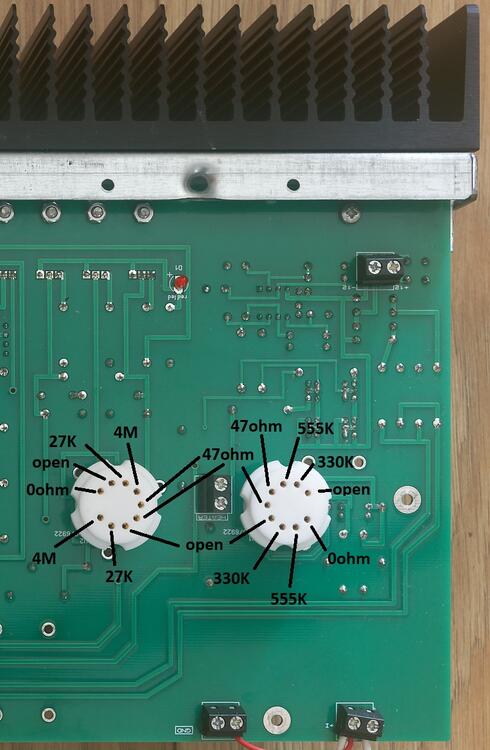
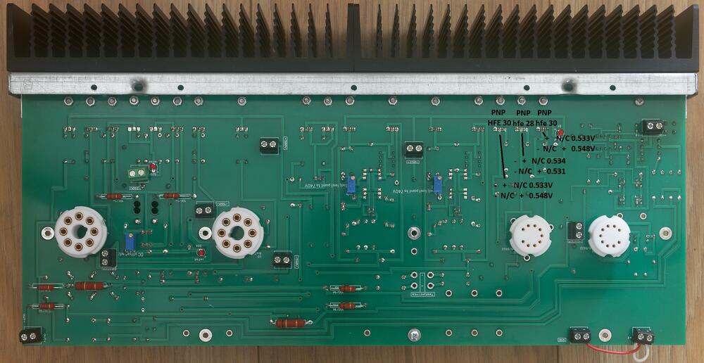
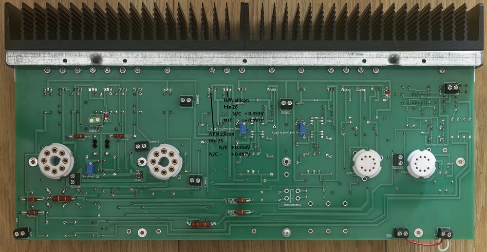
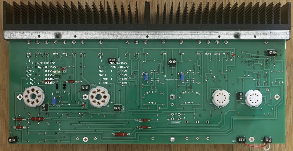
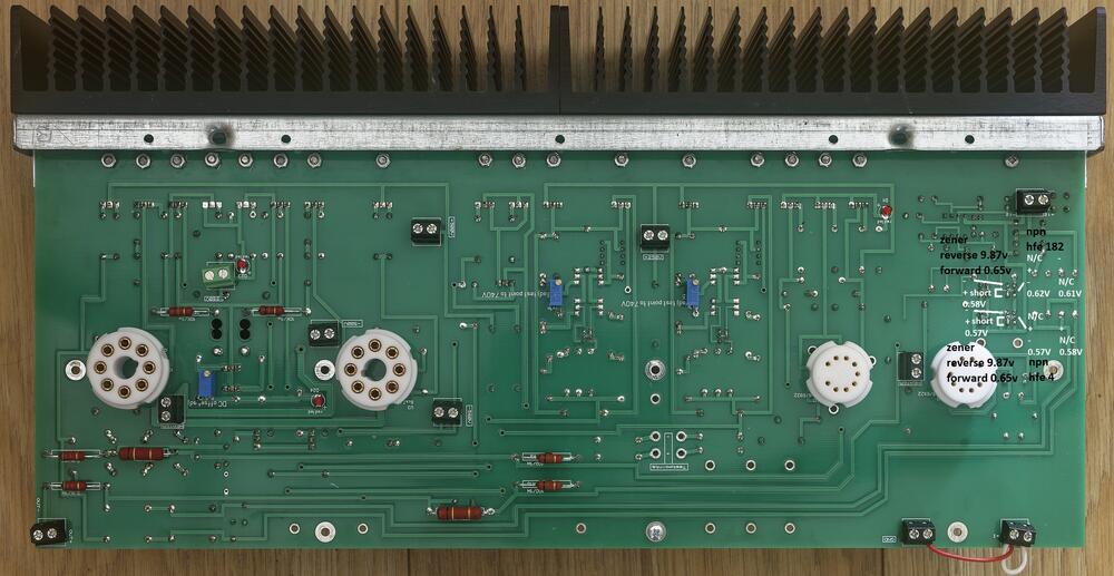
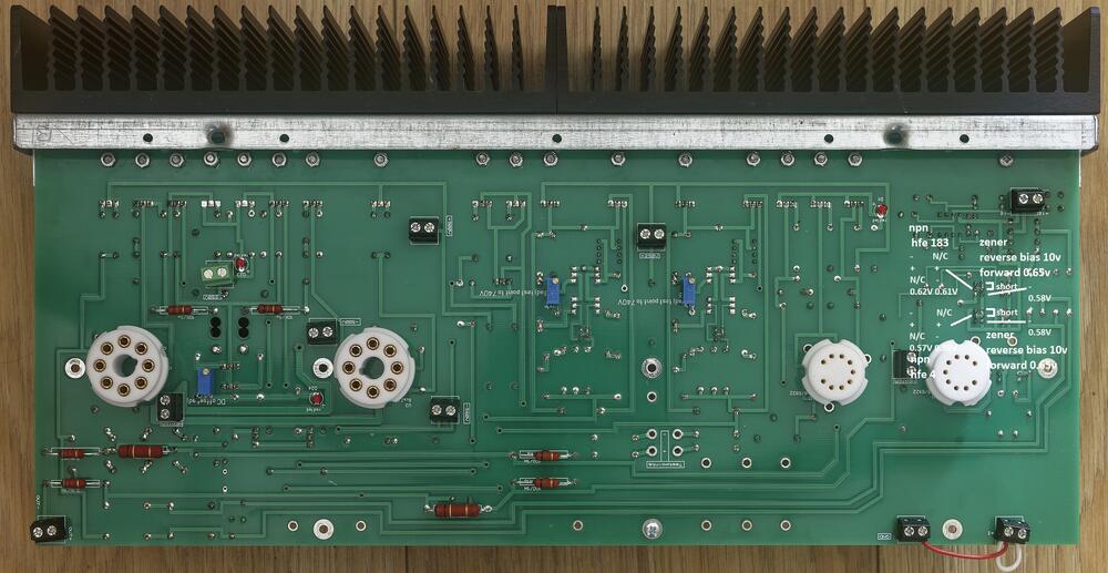
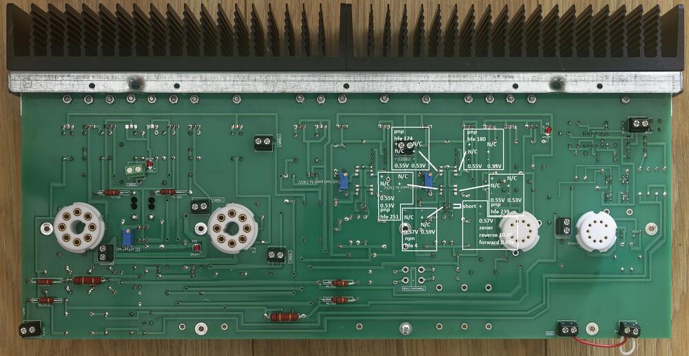
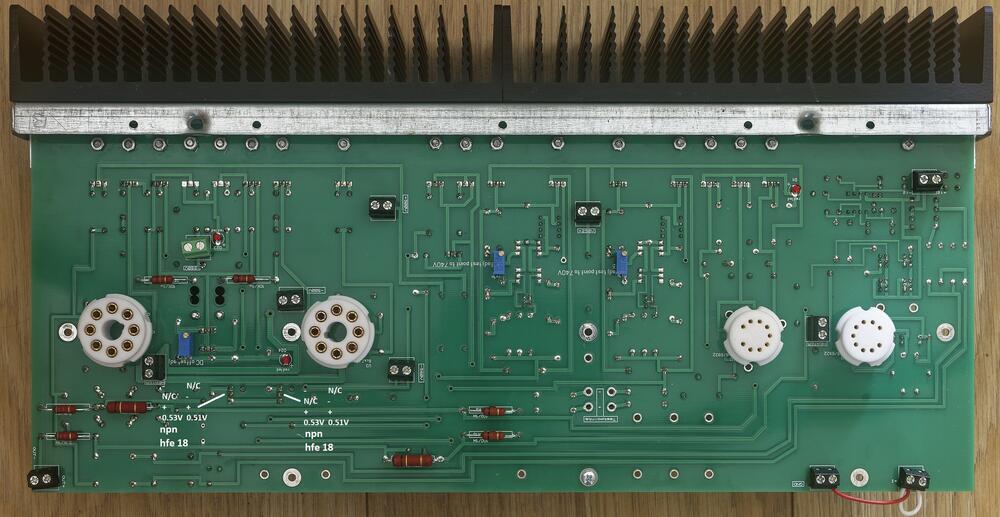
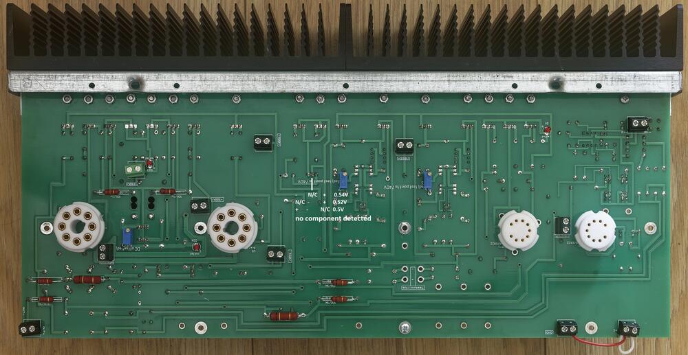
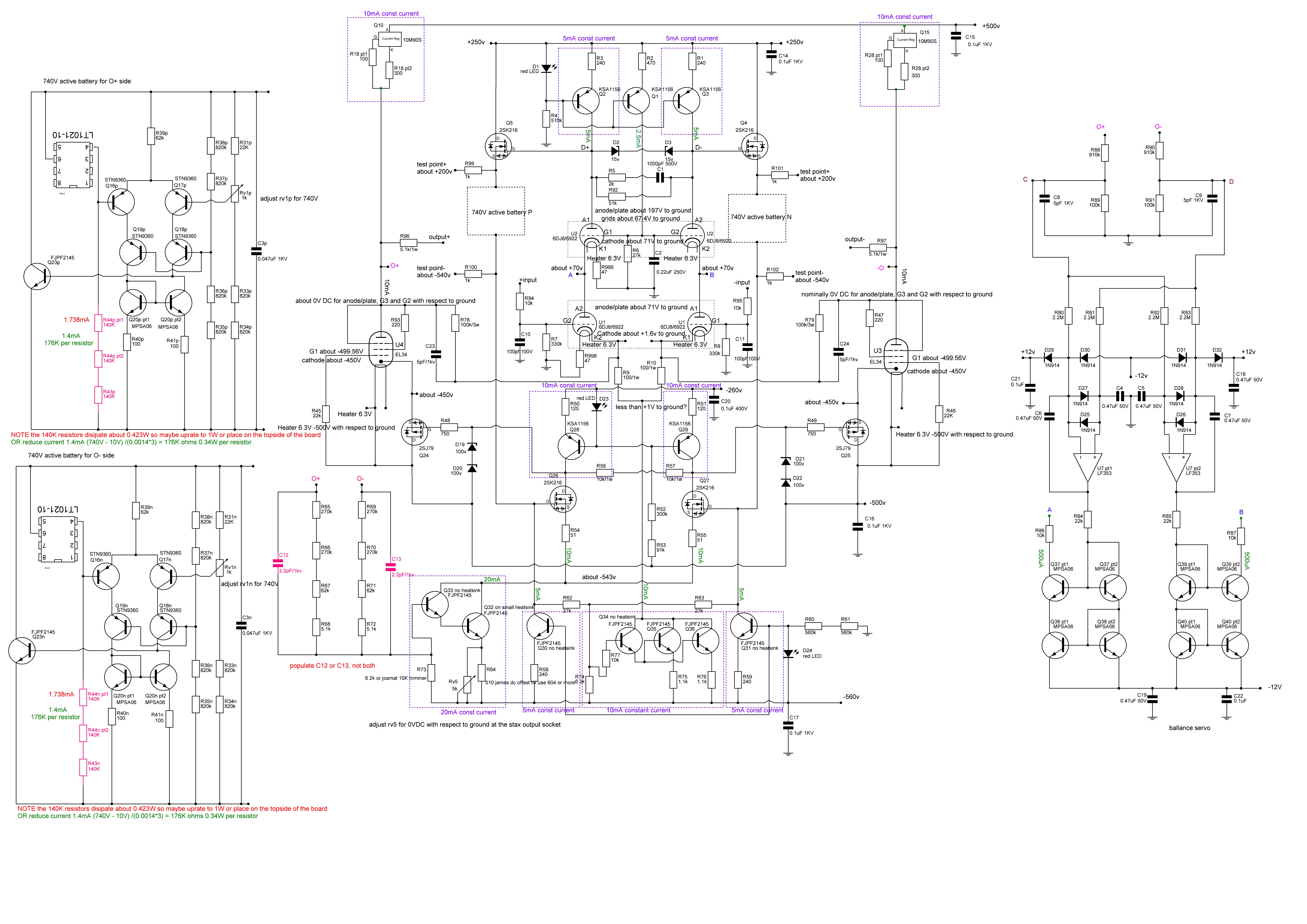
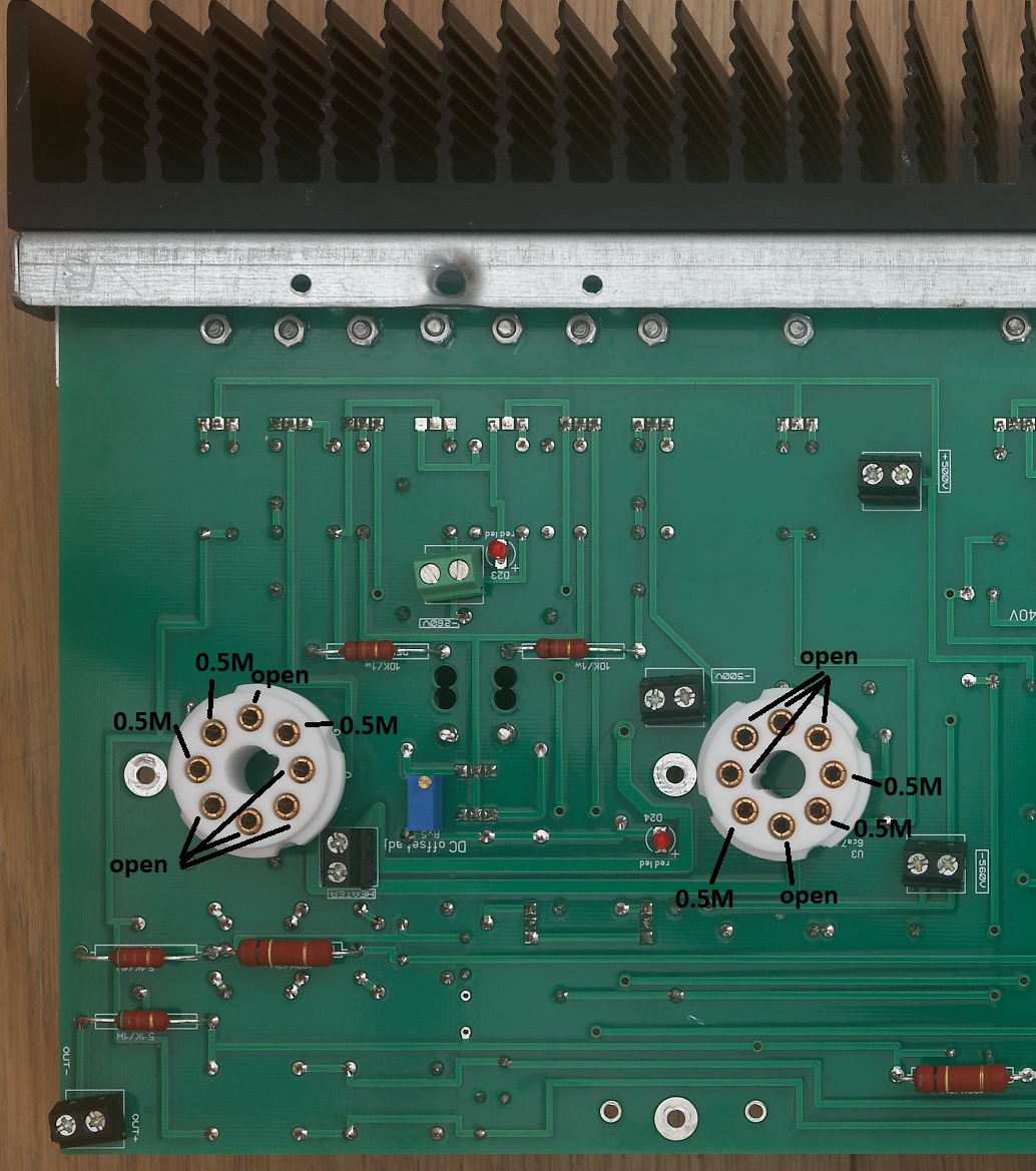
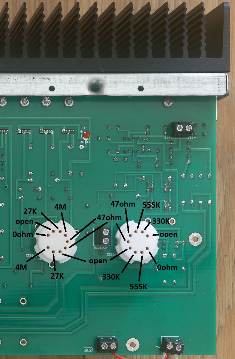
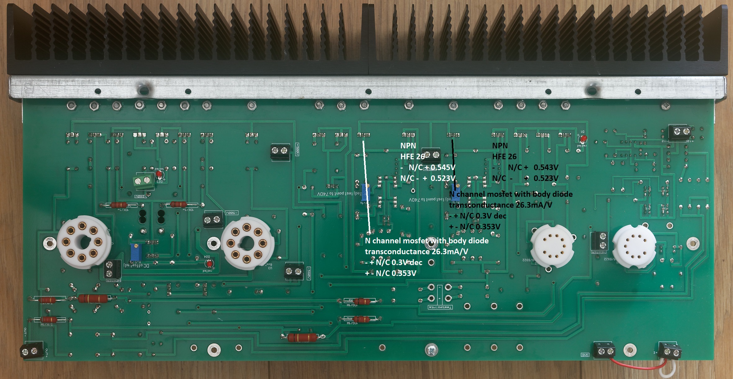
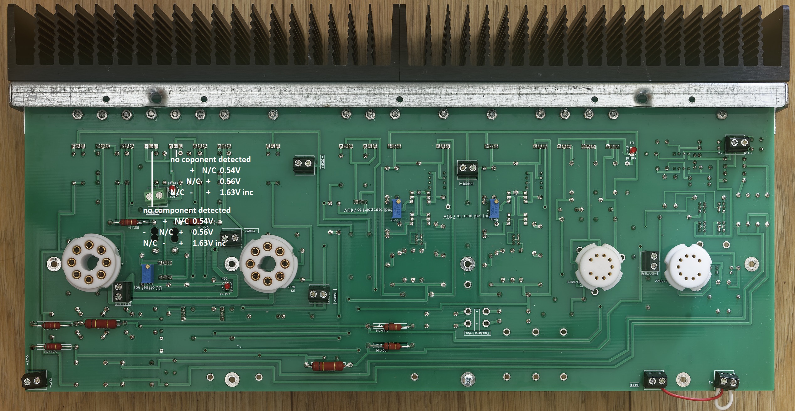
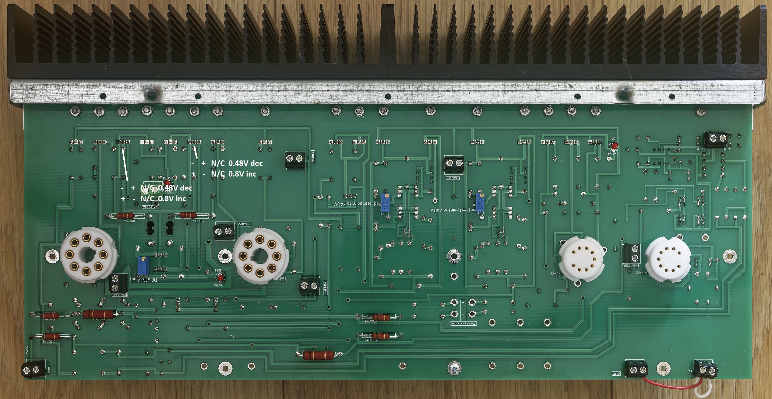
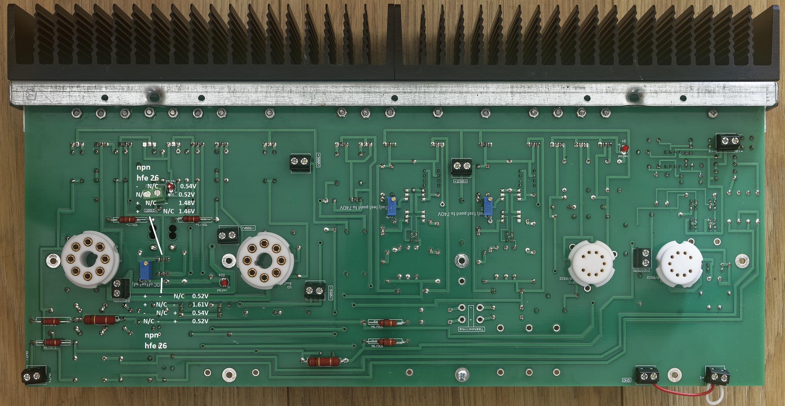
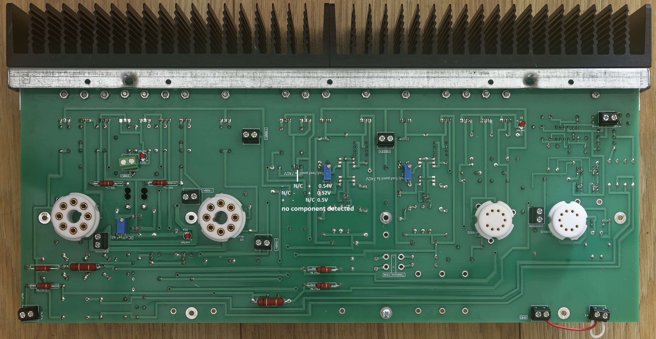
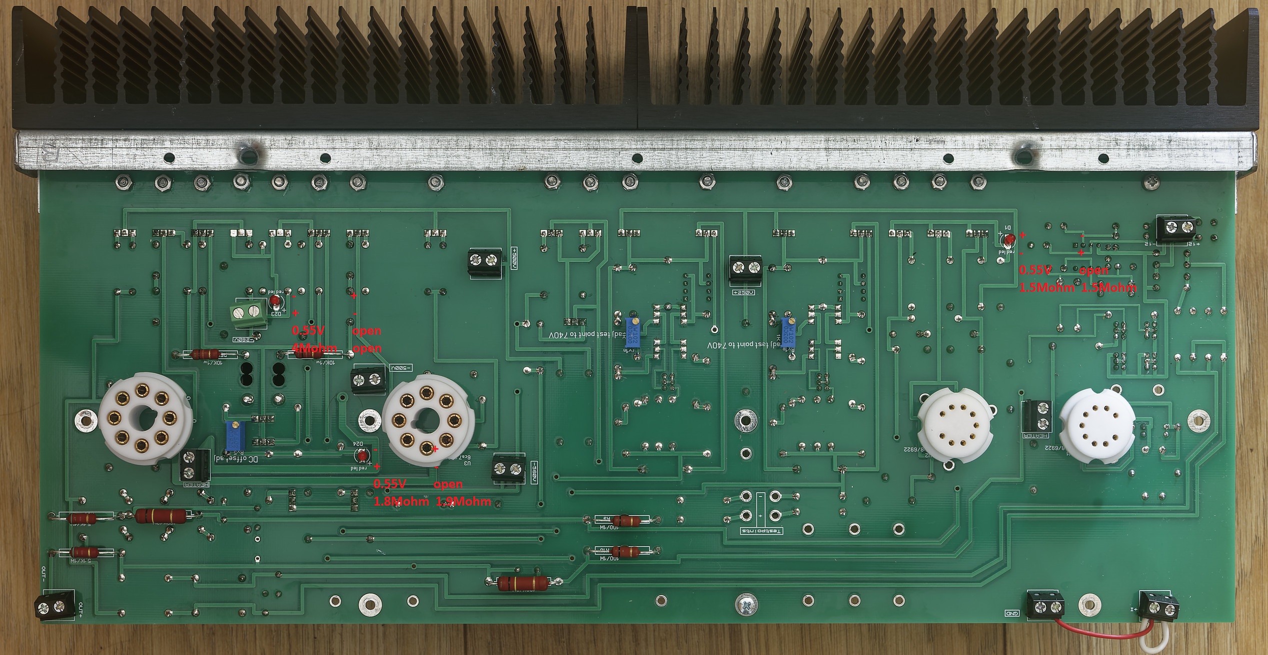
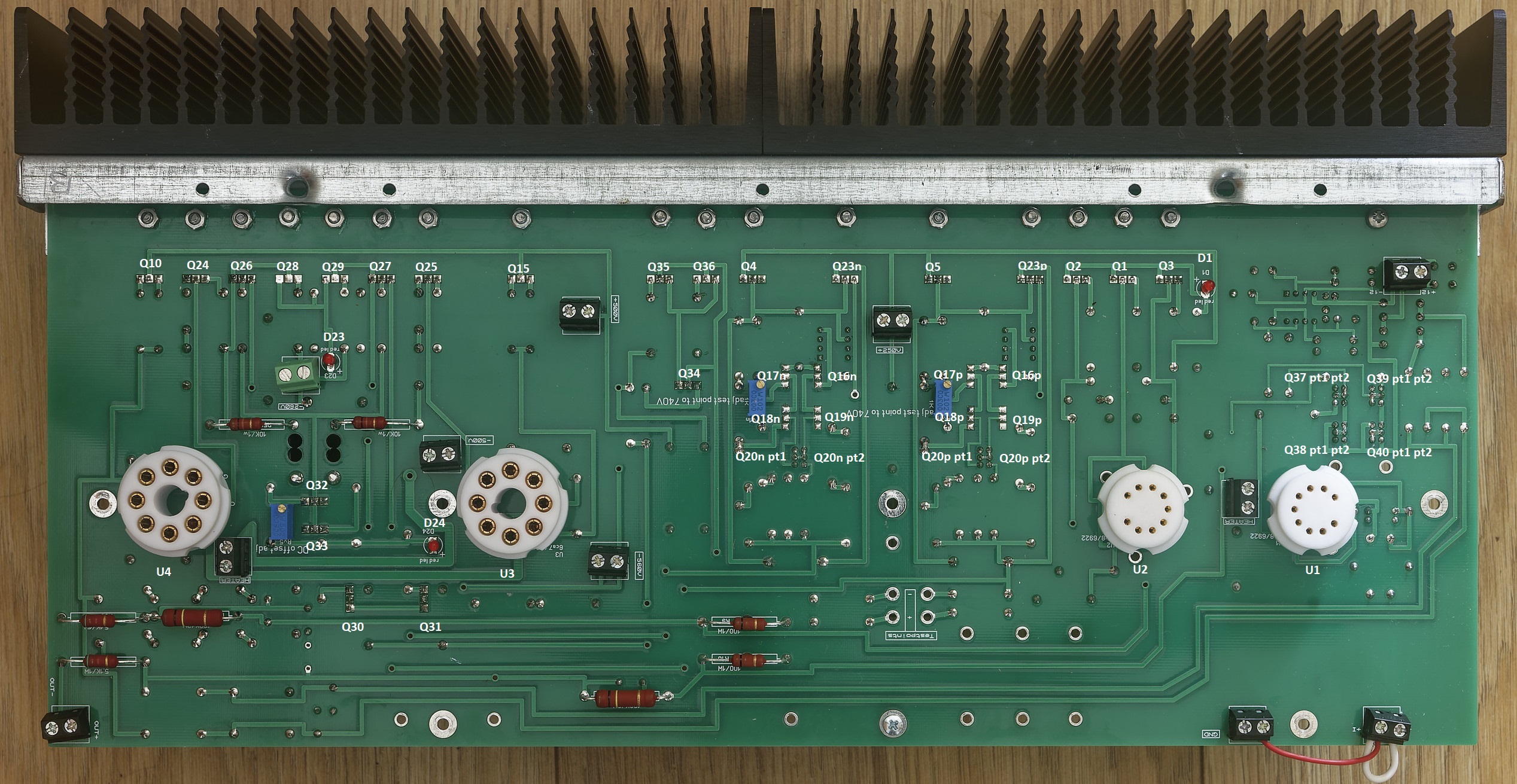
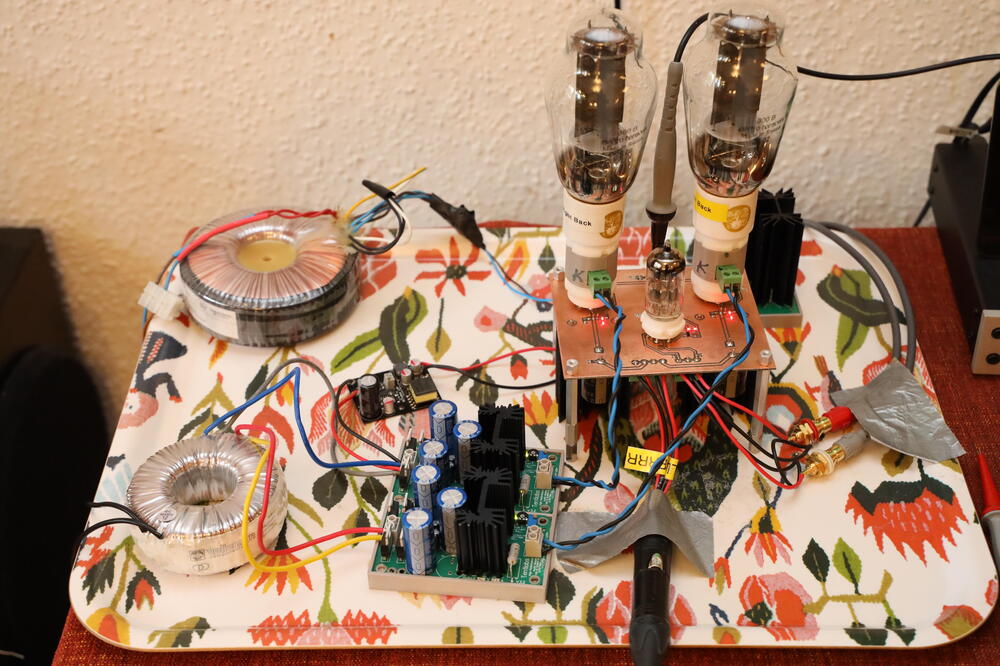 1 point1 pointThe unofficial mostly modern T2 troubleshooting and verification guide. Weclome, this guide covers the mostly modern T2 which has the following schematic: The gerbers for the amp can be found here: https://drive.google.com/drive/folders/1r3g2TAtBUaBdiMorTWX7yYgeJ7maQbYW and the gerbers are staxt2nc3fdh7.zip The guide is intended for both pre-power on verification of an amp build, verification of voltages on power on and general troubleshooting. All tests are performed using a Brymen BM869s and peak DCA75. Using a different multimeter may effect the results slightly but you should still get similar behaviours and ball-park figures. Transistor and Diode Location Section 1. Build verification with no valves installed and no wires/volume control connected to the amp All of these checks can be performed with a multimeter from the top side of the amp board leds Checks. All 3 leds on each channel should read about 0.55V voltage drop in forward bias (multimeter + terminal/red lead connected to led + and multimeter - terminal black lead connected to led -) and open circuit in reverse bias (swap the probes around) when tested with a multimeter in diode check mode. The leds will not light from the diode test due t the current draw if the components around them. The exact forward voltage drop will depend upon the characteristics of the red led but anything significantly different here indicates a problem. 0 voltage drop in both directions indicates a short across the led or the components it connected to. check for solder bridges and failed short transistors. 0L indicates in both directions means the led has dry solder joints or is blown. using a multimeter in resistance mode check the leds D23 close to the -360VDC psu input. In forward bias expect around 4M ohms. With the probes reversed you should get open circuit. D24 is the led closest to the octal socket for the EL34 and should read about 1.8M in forward bias and about 1.9M in reverse. D1 is between in the 9 pin sockets but close to the heatsinks. This should read about 1.5M in both directions. Readings in both directions of a few hundred K ohms or lower indicate the led may have been leaky or a transistor it is connected to has gone short circuit or a solder bridge. Input terminal checks With the multimeter in resistance mode and the - terminal connected to the amp ground, and the positive terminal connected to the + input of the amp you should get about 340K and the same for the - input. Naturally expect the same results for the other channel. If significantly different suspect incorrect resistors for R94, R7 (positive input). Or R95, R8 on the - input. Output terminal checks With the multimeter in resistance mode and the - terminal connected to the amp ground, and the positive terminal connected to the + output of the amp you should get about 0.5M and the same for the - output. Naturally expect the same results for the other channel. Valve Socket Checks. With the multimeter in resistance mode and the - terminal connected to the amp ground, and the positive terminal expect the following resistances for both EL34s: (socket viewed from the top of the amp). (note the 0.5M reading may start lower and quickly ram up and the small capacitors in the circuit are charged by the multimeter). For the 6922s (socket viewed from the top of the amp) Diode Checks of transistors Note it is possible for a transistor to fail in such a way it has very little gain but still has a diode drop and so diode checking transistors is not a foolproof measure of a transistors health. But 0V drop when not expected indicates a short etc. Diode checks KSA1156 checks Q1, Q2, Q3 two of the ksa1156s (Q2 and A3) measure the same in diode mode the centre one (Q1) differs slightly. All combinations of probes and pins on a transistor result in open circuit unless otherwise shown otherwise: + indicates positive multimeter probe attached, - indicates negative multimeter probe attached n/c indicates no probe attachment. Note: for the other channel EACH KSA1156 is rotated 180 degrees about the y (vertical) axis. Peak DCA in circuit testing Q1-3 The peak DCA 75 identifies all 3 transistors as PNP silicon. The centre with a hfe or around 28 and the other two with slightly higher hfe of 30 to 31. This test is reliable, anything significantly different indicates a problem. Note it is easier to do these tests from the underside although you can hook up the dca proe hooks to something like a sensepeek weighted self standing spring loaded probe tip assembly and test easily from the top (https://sensepeek.com/pcbite-20 Diode check and Peak DCA 75 for Q23P FJPF2145 This is reliably identified as a NPN with hfe 26 and is part of the virtual battery connected to the + output side of the channel. NOTE: It has a mirror image pinout compared to the ksa1156s. Diode check and peak DCA 75 check for Q5 2SK216 This is reliably identified as a N channel mosfet with body diode and has a transconductance of 23.3mA/V. Although not part of the virtual battery it is directly connected to it. WANRING This transistor has a live mounting tab and must be fully insulated from the heatsink. A resistance check from the metal tab to the heatsink it is mounted on absolutely must read open circuit. Diode measurement for this transistor does not show a stable reading. In this case dec indicates a reading that decreases over time. The next two transistors in the heatsink row are Q23N and Q4 which perform exactly the same role and are exactly the same type of transistors as Q23P and Q5 respectively and should measure about the same I got 28mA/V for the Q4 so expect a little variance here). NOTE: on the other channel the order of the 2SK216 and FJPF2145 are reversed. Diode check and peak DCA 75 check for Q35 and Q36 FJPF2145 These are the current providers (driven by Q34) for a 10mA constant current source that feeds the input 6922s. The job is equally divided between them and they should measure the same. The DCA75 reliably identifies them as NPN silicon hfe 25-26 Diode check and peak DCA 75 check for Q15 and Q10 (10M90S) These are identified out of circuit by the dca75 as N channel depletion mosfets. However, in this circuit they provide anode current and are wired in such a way the DCA75 can not identify them and reports no component. The DCA75 should not report any shorts and the metal mounting tab is live and absolutely must be insulated from the heatsink they are mounted on. Q15 and Q10 are identically configured and should measure the same. The gate and cathodes are connected together with resistors totalling only 400ohms so the diode drop voltages will be lower than for the other transistors also unlike the other transistors all combination of probes will result in a voltage drop. The voltage drop should be the same in the forward and reverse directions. Diode check and peak DCA 75 check for Q28 and Q29 (KSA1156) These are identified out of circuit by the dca75 as PNP silicon. However in this circuit they are wired in such a way the DCA75 can not identify them and reports no component. Each should measure the same. Diode check and peak DCA 75 check for Q26 and Q27 (2SK216) These transistors do not produce stable diode voltage drops. Diode check and peak DCA 75 check for Q25 and Q24 (2SJ79) These transistors are not easy to get a stable reading on. Diode and peak dca75 Check Balance servo Q37 - Q40 (MPSA06) 4 of the MPSA06es have their collectors and bases shorted together and so can be considered to only have two pins as far as diode checking concerned. NOTE for any transistor with shorted pins only two dca75 probes were used (one to the shorted pins and the other to the non shorted pin) to avoid the dca just reporting probes shorted. Understandably ni this case the dca75 can not identify the component as a transistor and instead reports a 9.87V zener. All other transistors are correctly identified and hfe provided. Diode and peak dca75 Check Virtual Battery Q16 - Q18 (STN9360) and Q20 (MPSA06) the other virtual battery in the channel (just to the left) should measure similarly and is identically laid out. Q20 pt 1 has collector and base shorted. All 4 stn9360 should diode measure similarly. NOTE for any transistor with shorted pins only two dca75 probes were used (one to the shorted pins and the other to the non shorted pin) to avoid the dca just reporting probes shorted. Understandably ni this case the dca75 can not identify the component as a transistor and instead reports a 10V zener. All other transistors are correctly identified and hfe provided. The stn9360 are pnp and the remaining non shorted mpsa06 as npn Diode and peak dca75 check Q30 and Q31 (FJPF2145) Each transistor provides a separate 5mA current source and are directly connected to the virtual battery. With the led D24 across their base and emitter. Each is identically configured and should read the same. Dca75 reliably identifies both transistors as npn both hfe 18 Diode and peak dca75 check Q32 (on seperate small heatsink) and Q33 (FJPF2145) this forms a 20mA current source which is controlled by Rv5 and sets the DC offset. DCA75 reliably identifies both transistors as npn both with hfe 26 Diode and peak dca75 check Q34 (FJPF2145) Q34 provides control for Q35 and Q36 which creates a 10mA current source. The dca75 says no component detected. <<< IN PROGRESS >>> #include <usual_disclaimer.h> #include <usual_high voltage_warnings.h>
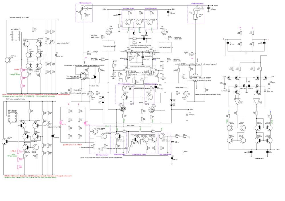


 1 pointWell, it didn’t take long for AI imagery to step over the line. https://petapixel.com/2023/11/07/adobe-stock-is-selling-ai-generated-images-of-the-israel-hamas-conflict/0 points


Important Information
By using this site, you agree to our Terms of Use.