

Leaderboard
-
Grahame
High Rollers15Points16720Posts -
naamanf
High Rollers10Points6660Posts -
Voltron
High Rollers8Points34512Posts -
acidbasement
High Rollers6Points2987Posts


Popular Content
Showing content with the highest reputation on 04/29/23 in all areas
-
7 pointsHad a picnic, in Belvedere Park with some of Joannes ex colleagues, one of whom now works in finance for the City of Belvedere, which isn't as relaxing as you might imagine, when questions on the state of the accounts from local residents include those from the ex Head of The World Bank. Following that, we had a leisurely stroll Around Belvedere , where we took in views of. Angel Island. The City (SF) shrouded in Fog. Likewise, The Golden Gate Bridge Fog rolling over the hills into Sausalito . And of course, Mt. Tam. A very pleasant afternoon.


 7 points
 -
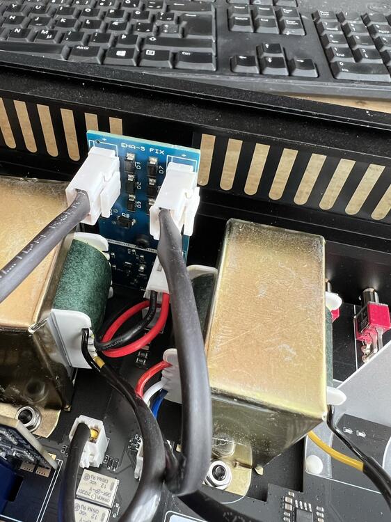
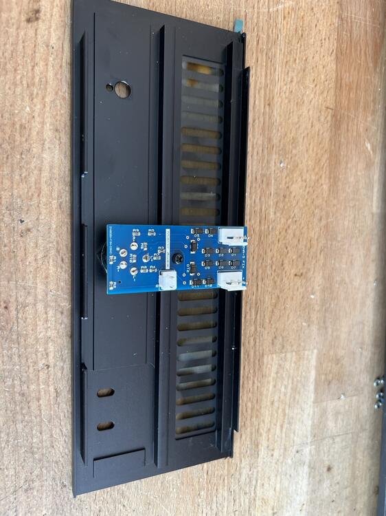
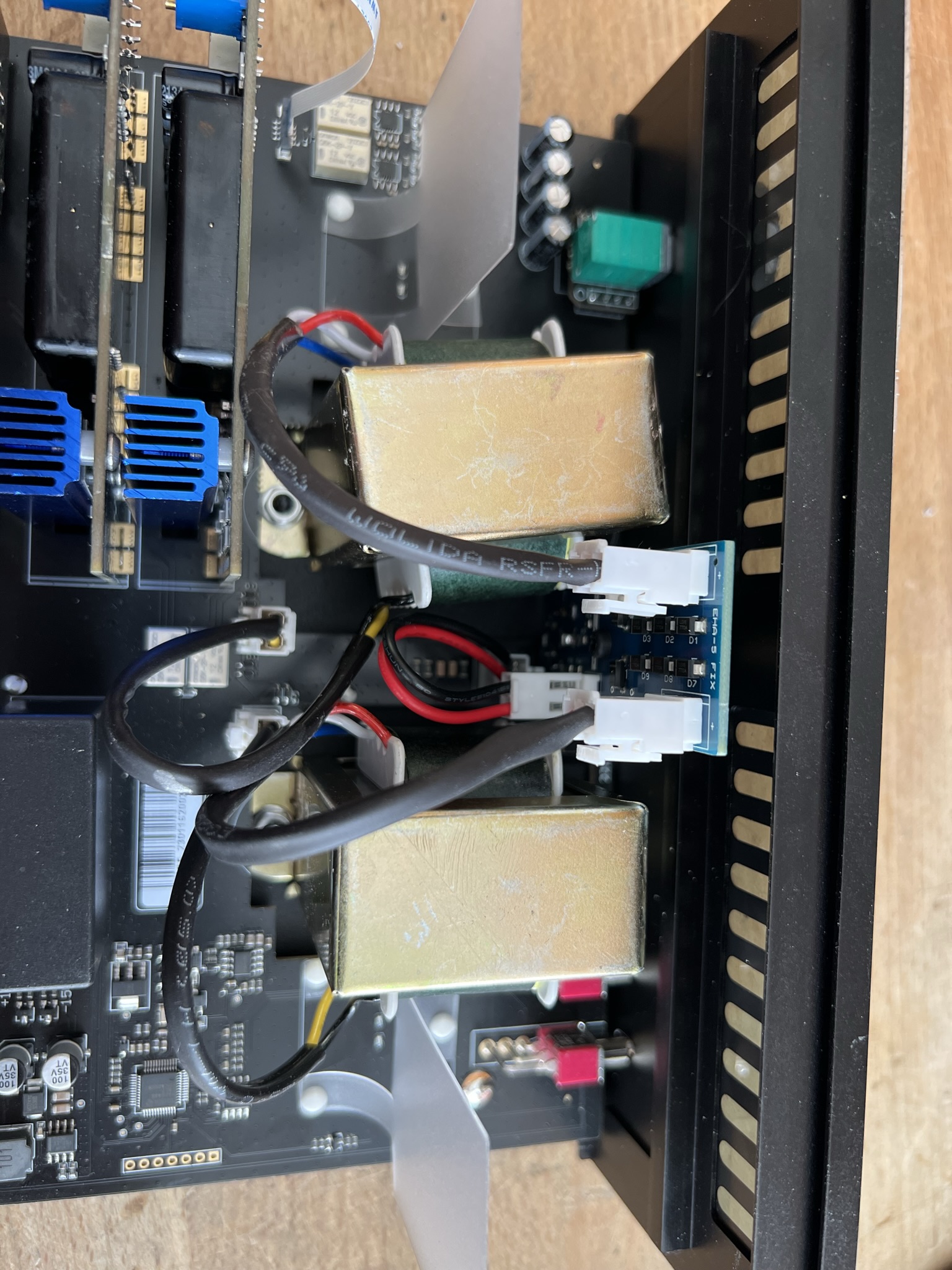
5 pointsThanks to the wonder of modern PCB manufacturing, this showed up yesterday: I bought the boards fully assembled as I'm lazy and I hate SMD soldering so I just had to add the connectors. To make it a single sided load (so the assembly would be much cheaper) the board had to be a bit wider than the stock board so one of the transformers had to be moved around 10mm. Just remove one screw and slide it to one side. Drill a new hole and it is done. Now the EHA-5 still sounds like shit but it is at least safe for the end user.

 5 points
 -
4 points
-
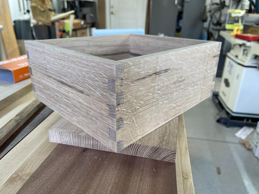
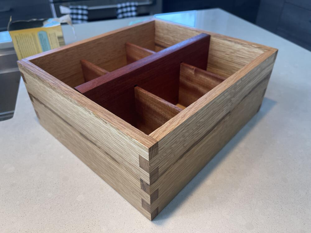
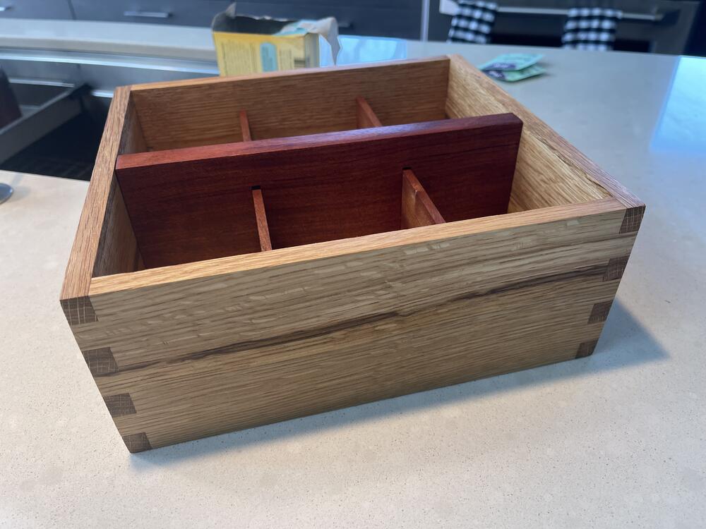
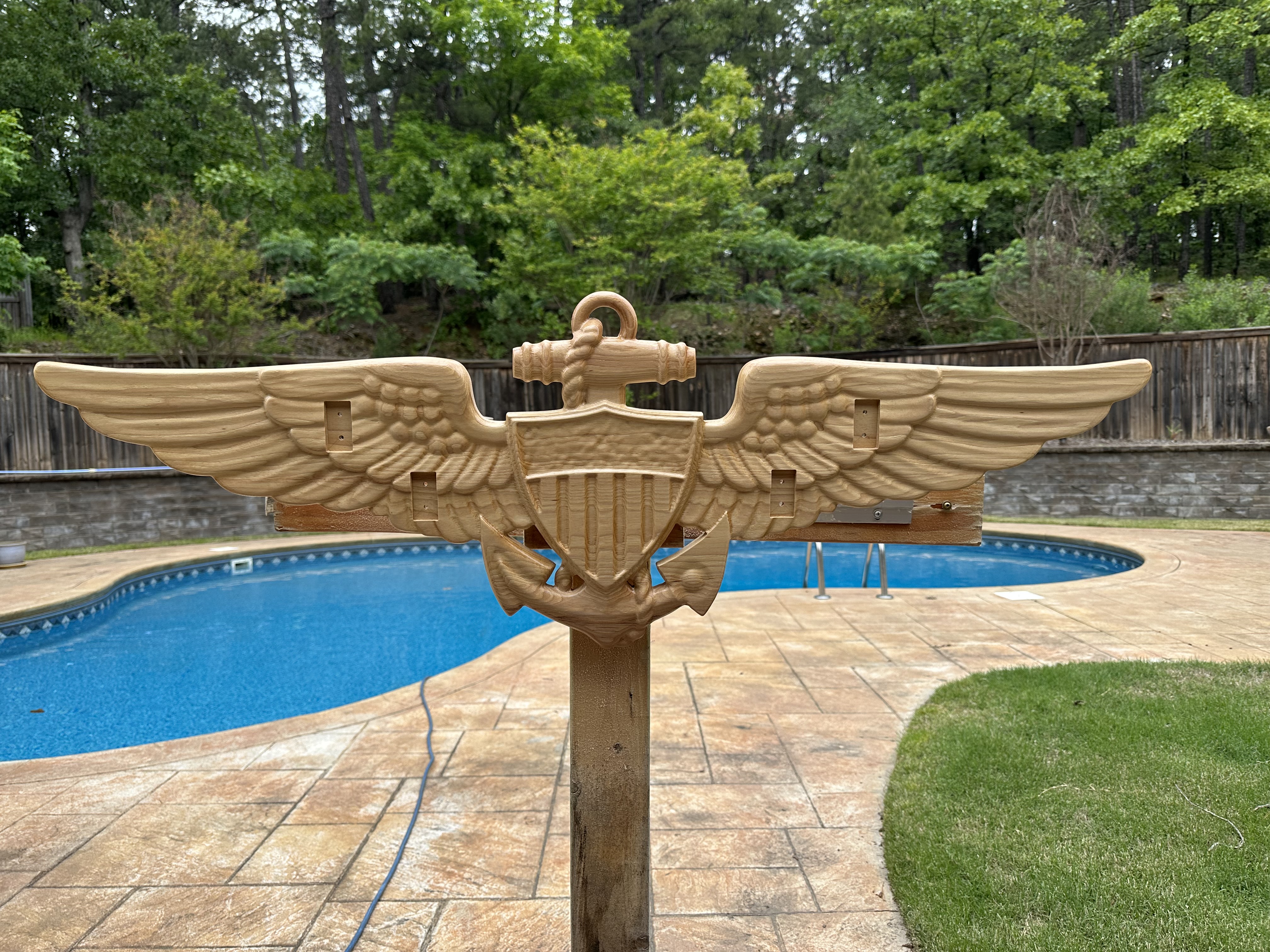
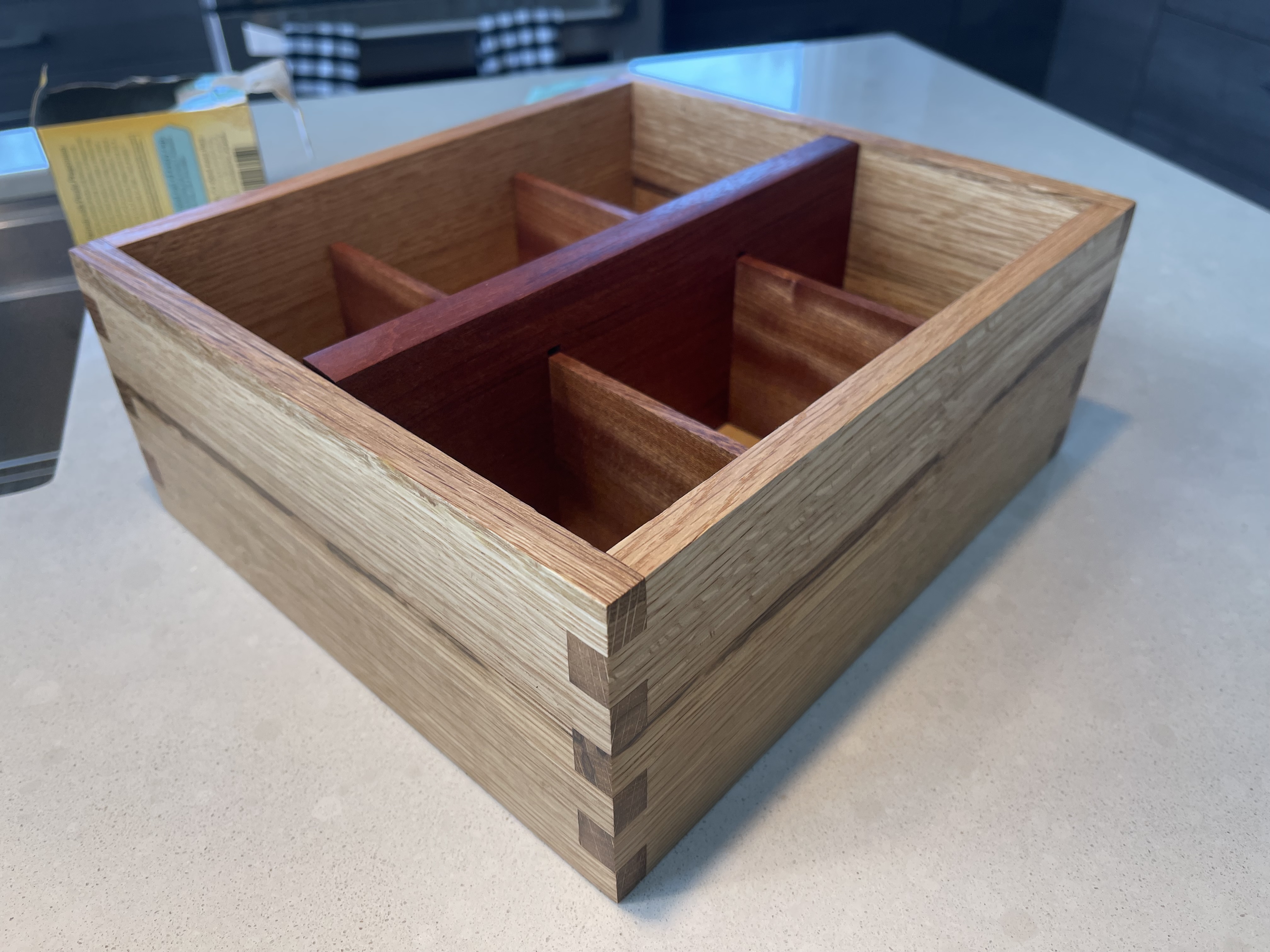
3 points3 pointsSomeone on the MV FB group I'm in got their account hacked and posted this obvious scam: So I posted my own version:2 points2 pointsI do like the overall design of it. And in the price range with a lot of things. It is a statement piece (i.e. not small). More like the monolith in 20012 pointsI built and have a GRLV that I use for my DynaFET configured for +/-30V and have used it ever since I got the DynaFET running, so probably 4 years or so (would have to look at the thread). I'm pretty sure the tantalums are 35V and never had any problem with them. I'll look later today to confirm. I never tested the MJFs or MJEs (would have to look also to see), but bought them from Mouser as I do almost all of my parts. In process of casing it so it is torn apart right now.1 point1 point1 pointalmost no authorized seller except farnell has MJF15030G in stock at the moment. Farnell has 347 https://uk.farnell.com/on-semiconductor/mjf15030g/transistor-npn-150v-8a-to220fp/dp/9556303 meanwhile the nonauthorized sellers claim to have about 300000 in total between them - I call BS... using a atlas dca75 pro I get hfe values of 89, 79, 87, 87, 95, 91, 98, 75, 108 for the 9 in my current stock (from radio spares, all purchased at the same time) - known good and used in GRLV. test conditions are: Ic 5mA, VBE 0.675V IB 5mA NPN silicon BJT. Spec sheet says 40hfe minimum for sensible currents.. no range or max is given.... My MJF15031 (from mouser) measure much higher hfes than the MJF15030. hfe 265, 263,264, 270, 263, 265,265, 269, 264, 266. So im getting a similar difference in hfe between the 30s and 31s as you are and a similar spread of hfes.1 point1 pointHave you not heard the joke, Grahame? A guy walks into a psychiatrist's office and exclaims "I'm a teepee! I'm a wigwam! I'm a teepee! I'm a wigwam!" Psychiatrist says "Calm down! You're two tents!"1 pointThis is very helpful advice. I will also add, that I broke a ton of taps until I realized.... 1. I was using the wrong size drill bit. M3 requires a 2.5mm bit. Not a SAE drill bit that is close. 2. Impatient, and just kept pushing (spiral fluted taps help if you are in a rush like me) 3. Buying junk taps on amazon1 point1 point1 pointBlessings and Miracles Santana 2021 https://album.link/i/1580765405 Example: Santana colab 2021. Overall I really liked it. There is the Example, which is just a bop. To some lovely things with Steve Winwood and the late Chick Corea. Warm Friday evening music.1 point1 pointMy ex boyfriend's safeword was "harder". It made for a lot of confusion.1 pointWhen Steve gives a suggestion on country music, I listen.1 pointThe older I get the more I think still lens and cine lens people don't have much in common (even historical references), but... https://www.kickstarter.com/projects/moment/the-tuner-create-classic-cinematic-looks-on-your-camera1 point1 point1 point1 point1 pointThrew together a little quartersawn tea box today with box joints and dado for the bottom all done with the Shaper.
 1 point1 pointSoft start would be nice... …if it works. Not sure it will, but I know a way to find out. Above is based and inspired by this:
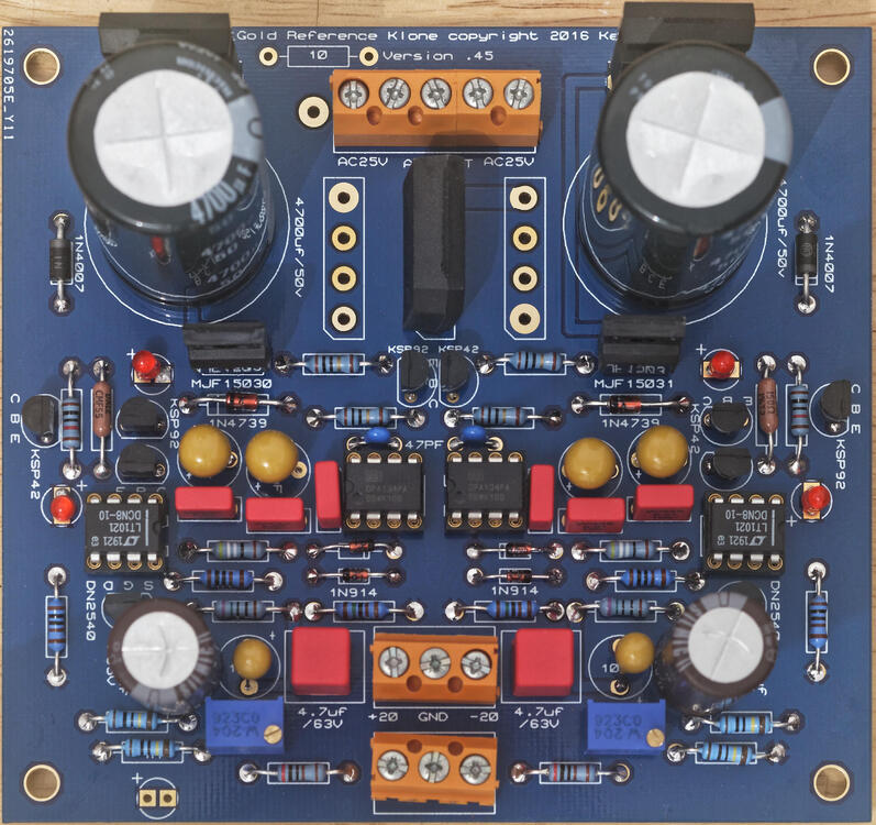
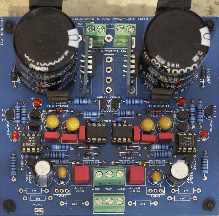
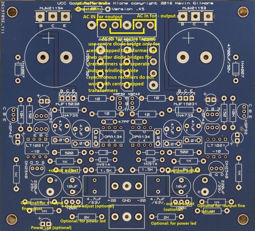
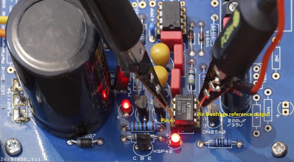
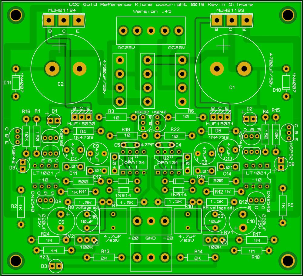
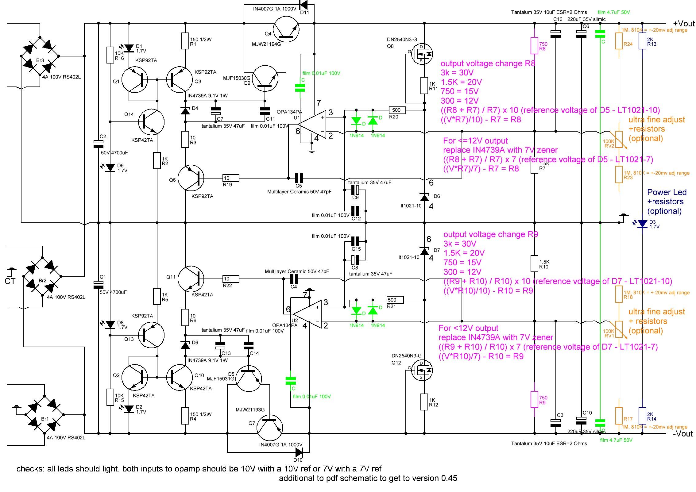
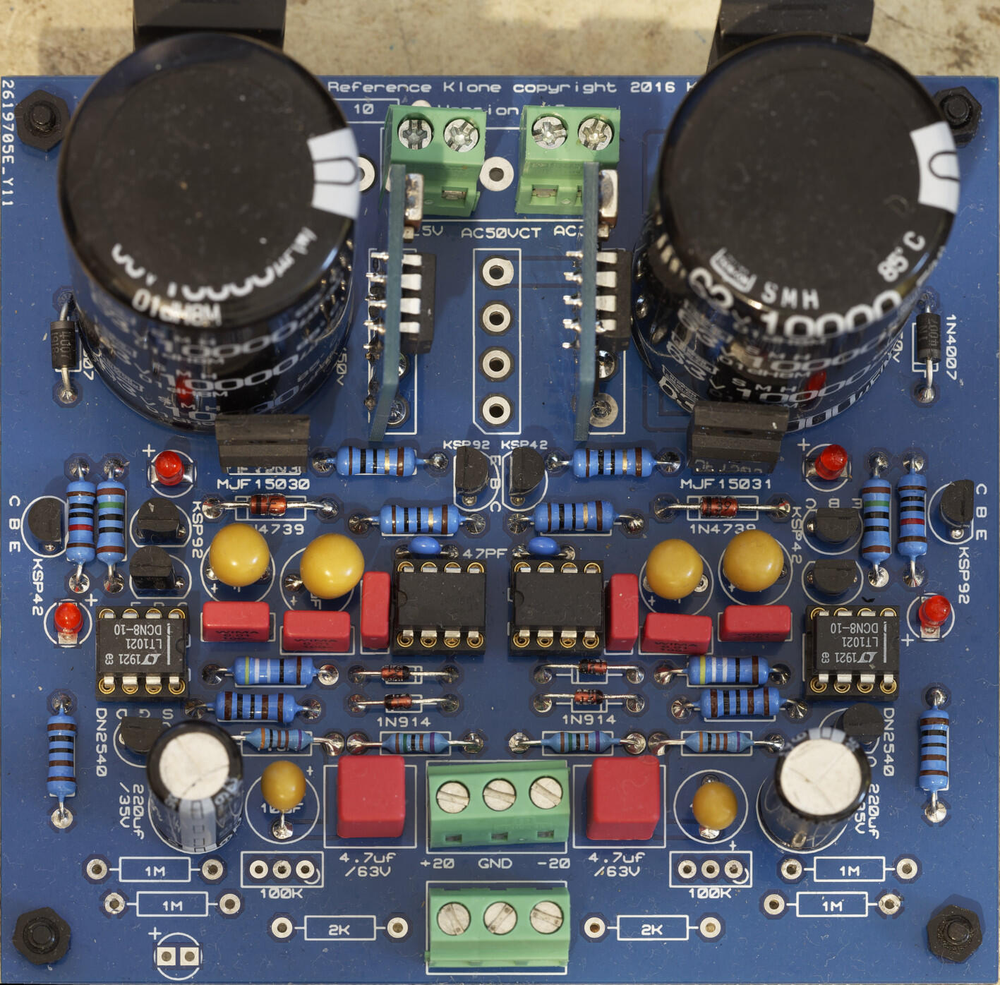
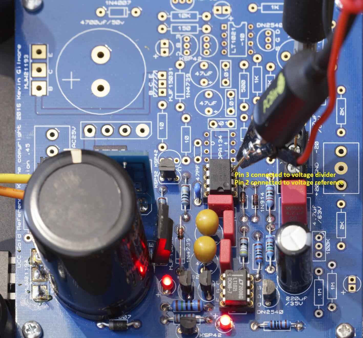
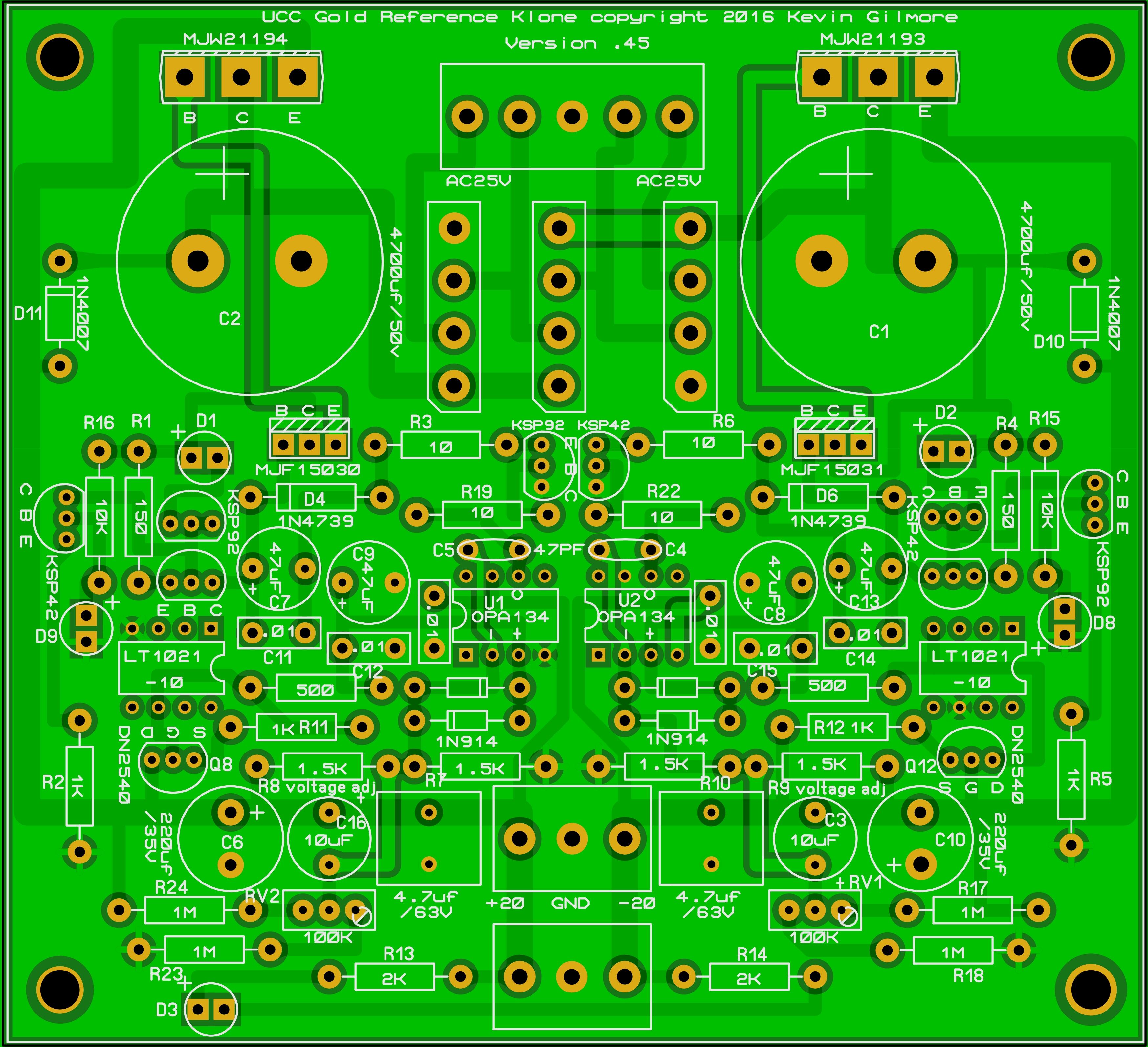
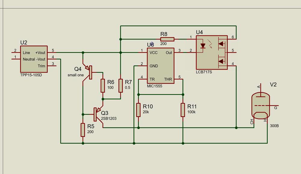 1 pointTracey's voice has definitely "aged" - not necessarily in a bad way. Their new album Fuse is pretty nice, they kept going with the modern sound and it's quite good (as much as I loved their more ballad-like songs).1 point1 pointStacey Ryan. One of the young talents whose career I'm following1 point1 pointreference voltage is the LT chip 10V normally or 7V version for <=12V output. As mentioned in my original post the opamp compares the reference voltage to a portion of the output voltage and corrects any difference. So for a 20V grlv you will use the standard 10V reference which is in the bill of materials. The grlv is so low noise it could be used in many situations e.g. as a voltage standard for calibrating other equipment. In that case a precise output is needed, hence the trimmers. The wider the range of adjustment the lower the temperature stability which if you are using it as a voltage standard is a potential issue. For a power supply in an amp having exactly 20.000V output rather than 20.1V is not an issue. This is why I don't populate the trimmer adjustment. Kevin even build a grlv using extremely expensive very low ppm resistors and measured the voltage drift over an entire day just to see how the the grlv was and the result was extremely stable but the resistors alone probably cost more than your amp build.... In my experience power supply caps do not make a massive difference to the sound. I go for low effective series resistance and high reliability. Dont forget most of kevins designs have 0.1uF power supply byass caps on the amplifier boards themselves. This cuts out some noise picked up in the wires between the psu and amp boards. So in effect the 4.7uF caps are bypassed anyway (I am not familar with your amp build but its worth checking the amp pcb to see if it has bypass on it - some of the published amp schematics don't show the bypass caps but they are on the pcb.). Where they matter more is when they are in the audio path e.g. as a dc blocking capacitor between two amplification stages. Most of kevins designs use dc servos to cancel the dc and avoid the use of coupling caps in the audio path. The only exception to this I have built is the Megatron and currently that just used wima caps. for the cost of parts connect "audiophile" caps you could be well on the way to buy a cheap ebay variac.... I find the panasonic FR series caps for the 220uF output cap sound good and are quite cheap. I use a wima for the 4.7uF. Kevin measured the GRLV in a clean room when he was working at a university and the noise levels are incredibly low. bypassing the film cap with a medium value pF ceramic or similar might reduce the output impedance at very high frequencies but some ceramics e.g. multi layer can be microphonic... variac is useful especially if you plan to build high voltage power supplies and can also be used to slowly power up the entire amp when completed in case their are issues with the amplifier boards. But if you are on a tight budget a variac is not necessary. You could do the grlv tests powering it up with a current limited dc power supply if you have access to one. DC load is useful simply for its versatility. In reality if it powers up under no load with no issues its probably fine. I use my variac a lot. The reason I like a variac is 1. I can bring up the board slowly and check for overheating components. before there is so much energy in the circuit things go pop. 2. I know if the outer leds don't light at a certain input voltage I have a problem and can stop the testing immediately. If I see the output increasing past the point where it should regulate I know I have a problem. Im paranoid and its all about finding issues at as low voltage and therefore low stored energy as possible to minimise damage. This technique has saved me money. 3. I might not have a transformer with the correct outputs for the power supply I am building and I can use the variac to reduce the output of a transformer to the level I need. e.g. lets say I need 23VAC for my 20V output grlv and I only have a 50VAC transformer. 50VAC might be too high for my chosen input cap and if its not I will get considerable heat in the transistors as they try to drop the large excess input voltage. Instead I turn the variac up until I get the output voltage I want from my transformer... That way I only need to keep one low voltage transformer around to test any grlv and one high voltage transformer to test any GR HV.... 4. if you are planning to build high voltage power supplies the build cost and potential for nasty damaging failures are higher and a variac can reduce the collateral damage if something goes bang. If you are only planning to build one thing and are on a tight budget and build carefully a variac is a luxury rather than a necessity. There are designs for DIY DC loads on the internet I built it myself and wrote custom code for it. My philosophy is test everything especially power supplies well. Also sometimes forum members ask about particular loads or when loads are "safe" or heat output or voltage drop at certain loads. I also can also use it to test the true capacity of batteries, usb power banks etc. In other words its a useful experimental tool for me. If you are on a budget some high wattage resistors would be fine. If you decide to load test at all. voltage drop = current * resistance so if you are outputting say 20V and want to test at say 0.1A (100mA) then V/I = R 20V / 0.1A = 200ohm. power = V * I so 20V *0.1A = 2W so a 5W 200ohm resistor should be ok for this current draw. power requirement will go up with current draw so for 0.5A at 20V you will need a 40ohm resistor and the power dissipation will be 10W so at a minimum you will need a 15W resistor. Many high wattage resistors specifications assume they are bolted at a suitable heatsink so by the time you have purchased a range of resistors and some heatsinks you can get into the price range of a diy dc load which could handle 100V multiple amps be programmable, run automated tests etc.. If you then build a power supply with a high output voltage say 30V all these resistors will have too low wattage ratings and the current draws will also be higher. A Dc load provides a current draw which is independent of the output voltage of the device its testing. load resistors cant do that. But again if you are only planning to do one build and or are on a budget load testing is optional. Im using a cheap one of ebay. It works for me. the grlv is an easy build (unlike the gr78/79xx smd boards), so as long as your soldering technique and attention to detail are good there is a very good chance your grlv will work first time. I wanted my build guide to be comprehensive, it was not my intention to scare you into buying test equipment you might not use much. Good luck with your build. James1 pointGolden Reference LV Build Guide Schematic for the golden reference LV: parts in green are new additions compared to the published schematic pdf in joamats post above. Parts in purple set the output voltage, parts in brown are the optional fine output adjust and parts in dark blue are the optional power led. Component Layout Optional parts and Options: 1. if you don't want to have a power led fed from the LV board omit the 2K resistors R13, R14 and the led D3 2. if you don't want very fine adjustment of the output voltage omit the 1M resistors R17, R18, R23, R24 and the trimmers RV2 and RV1. If you want more adjustment range reduce the value of the resistors. With 1M ohm resistors the fine adjust can only change the output voltage by a few mV. Replacing with 810K resistors provides a little more adjustment range ~ 20mV but at the expense of decreasing the temperature stability. A cheaper alternative for good output accuracy is to use 1/4W 0.1% low ppm e.g. 15ppm resistors for the voltage set resistors and omit the fine adjust completely - which is cheaper and improves the temperature stability. 3. if you have the dual output board (which has both positive and negative output rails) either you populate the middle diode bridge only and use a transformer which is centre tapped OR you populate the two outer diode bridges and use a transformer with two separate output windings. If use use synchronous rectifiers instead of diode bridges use must use the second option and use separate windings for positive and negative rails. Do not populate all three bridges. If you use a centre tapped transformer you must connect the centre tap to the middle screw terminal (which is connected to the GRLV ground plane) of the 5 terminal AC input block . Do not use a synchronous rectifier to the centre bridge it will not work correctly and can result in the driver mosfets of the synchronous rectifier burning. Note the GRLV cant output less than the voltage of the voltage reference (LT1021), ideally for proper regulation the output needs to be more than about 2V higher than the LT voltage reference. So for about 12V or less output it is recommended you change the 10V reference for a 7V and the zener diodes for a 7V. For 12V output 10V reference or 7V reference can be used but the 7V reference version may have less noise. Maximum output is constrained by the voltage rating of the caps and is about 30V without modifications. Setting the Output Voltage For the positive output R8 and R7 control the output voltage along with the voltage reference, the output voltage is ((R7+R8)/R7)*voltage reference output D5. Assuming you keep R7 at the stock value of 1.5K: output voltage change R8 to 3k = 30V 1.5K = 20V 750 = 15V 300 = 12V In general to calculate R8: ((Voltage required * R7)/voltage reference D5 output) - R7 = R8 For the negative output R10 and R9 control the output voltage along with the voltage reference, the output voltage is ((R10+R9)/R9)*voltage reference output D7. Assuming you keep R10 at the stock value of 1.5K: output voltage change R9 to 3k = 30V 1.5K = 20V 750 = 15V 300 = 12V In general to calculate R9: ((Voltage required * R10)/voltage reference D7 output) - R10 = R9 Photos of finished boards for reference: This version uses a single diode bridge so this is setup for a centre tapped transformer, also has the trimmers and resistors for the power led populated but no power led installed. The build uses 4700uF reservoir caps and silmic 220uf output caps and 1/4w resistors from vishay and dale. This is what you get using the BOM link in this post (see bellow) and is very close to the original BOM published near the beginning of this thread. This version is setup for dual separate transformer windings, and has no power led or trimmers implemented. It also uses synchronous rectifiers instead of diode bridges, nippon chemicon 10000uF reservoir caps, Panasonic FR series 220uF caps and 1/2W 50ppm 1% koa resistors. The resistors that set the output voltage are 1/4W TE 0.1% 15ppm for increased temperature stability and output accuracy. This is my current default build. BOM (based on 10V voltage reference and all options being populated) https://www.mouser.com/ProjectManager/ProjectDetail.aspx?AccessID=edda1bdbf7 Component list with cap size information Br1,Br2,Br3 = 2 x 4A 100V RS402L use 2 for dual winding transformer use 1 for centre tapped transformer C,C = 2 x film 4.7uF 50V 5mm lead spacing 0.5mm lead diameter C,C,C11,C12,C14,C15 = 6 x film 0.01uF 100V 5mm lead spacing max size ~ 7.6mmx3mm 0.5mm lead diameter C1,C2 = 2 x 50V 4700uF 10mm lead spacing max diameter 25mm, 22mm more comfortable fit main reservoir cap I also use Nippon Chemicon 63V 10000uF which just fit. C3,C16 = 2 x Tantalum 35V 10uF ESR=2 Ohms 5mm lead spacing 0.5mm lead diameter C4,C5 = 2 x Multilayer Ceramic 50V 47pF 5mm lead spacing 0.5mm lead diameter C6,C10 = 2 x 220uF 35V silmic or Panasonic FR series 5mm lead spacing 12.5mm max diameter C7,C8,C9,C13 = 4 x tantalium 35V 47uF ESR=0.8ohms 5mm lead spacing 0.5mm lead diameter D,D,D,D = 4 x 1N914 D1,D2,D3,D8,D9 = 5 x 1.7V red led 4 are required one is for optional power led leally all 4 main leds should be from the same batch and have similar characteristics. D10,D11 = 2 x IN4007G 1A 1000V D4,D6 = 2 x IN4739A 9.1V 1W use 7V zener for <=12V output D6,D7 = 2 x lt1021-10 10V voltage reference use 7V for <=12V output Q4 = 1 x MJW21194G Q5 = 1 x MJF15031G Q7 = 1 x MJW21193G Q9 = 1 x MJF15030G Q1,Q3,Q6,Q13 = 4 x KSP92TA Q2,Q10,Q11,Q14 = 4 x KSP42TA Q8,Q12 = 2 x DN2540N3-G R1,R4 = 2 x 150 1/2W R13,R14 = 2 x 2K R15,R16 = 2 x 10K R17,R18,R23,R24 = 4 x 1M, 810K = +-20mv adj range optional for fine adjustment R2,R5,R11,R12 = 4 x 1K R20,R21 = 2 x 500 R3,R6,R19,R22 = 4 x 10 R7,R10 = 2 x 1.5K R8,R9 = 2 x 750 for 15V output change as necessary for your output RV1,RV2 = 2 x 100K optional for fine adjustment U1,U2 = 2 x OPA134PA opamp Building Once you have decided the build options and output voltage, construction is straightforward given there are no high voltages. Depending upon the current draw the large power transistors on the side of the board may require heatsinking. The metal tab is live so they will need to be insulated from the heatsink/chassis. Socketing the reference and opamps is optional but it does make replacement and reuse easier. Make sure the caps are installed with the correct polarity. The line on the tantalums denotes the positive Terminal whereas the line on electrolytic caps denotes the negative terminal.... the film caps can be installed either way around as can the small ceramic caps. For the leds the longer leg is the + leg and this goes to the + mark on the pcb be careful to install the opamps and voltage reference chips the correct way around they will get very hot very quickly if installed the wrong way. make sure you don't place as ksp42 where a ksp92 should go of visa versa. Its easy to do since they look identical and its not easy to see all the markings once populating the board is finished. Testing (optional) If you have a means to control the input voltage to the board e.g. a variac, then with no load connected to the grlv the outer leds (closest to the LT voltage reference) should just start to glow at about 2.4 to 2.5VAC rms input voltage to the board and the output of the GRLV should be around 1V DC. If you cant get the outer leds to light with about 3VAC rms input, stop and disconnect, something is definitely wrong. By 3VAC rms the outer leds should be bright. Increasing the variac output further should see proportional rises in the GRLV DC output voltage until the output reaches the expected output. At this point the inner leds closest to the zener diode may not have lit and although basic regulation has been achieved, the input voltage is too low for full low noise regulation. Increase the input voltage a little more and the inner leds should light. This should happen with after about an additional 1 volt AC rms is added to the input. The output voltage should not increase. As a very rough rule of thumb, without load, the grlv needs about 2V less input AC rms than its DC output. So for example for 12v output expect regulation to just happen at about 10VAC rms input but the inner led not to light until about 11VAC rms. Note this figures depend on tolerances, the diode bridge voltage drop, led characteristics etc and are a rough guide only. Adding a load to the GRLV will mean it needs a higher input voltage in order to regulate since some of the sources of voltage drops are dependant on current draw e.g. the diode bridges. So if you adjust the variac to just get the inner led lit with no load don't be surprised if it goes out when you draw a few hundred milliamps. Another way to test is to connect the AC in of one rail to a current limited DC power supply. Set the current limit to say 0.010A (10mA) and slowly increase the voltage. Bellow about 3.3VDC input to the GRLV there should be low current draw <10mA. At about 3.4VDC the outer led will start to light and current draw should still be <10mA. Around 8.5VDC input current draw should reach about 10mA. The inner led close to the main cap should begin to light at about 2.6VDC input above the expected output e.g. 14.6VDC input for 12V output. At this point current draw should be about 20mA and you may need to increase your DC power supply current limit. Increasing the DC power supply output past this point should not result in increasing current draw or increasing GRLV output. Note when you increase the DC power supply voltage you will get an initial current draw spike as the input cap charges to the new voltage level but the current draw should quickly subside to the figures shown. If the GRLv regulates and behaves as expected with no load and has no warm components or varying output then you could continue to load testing. The reality is that if your RLV works with no load its almost certainly ok and will be fine without load testing. But if you want to be extra careful the easiest way to do this is with an electronic DC load. I setup my load so that it will abort the test if the output voltage of the GRLV exceeds 0.2V above or bellow the no load output. A properly working GRLV with enough input voltage will vary very very little with current draw - much less than a traditional 78xx/79xx voltage regulator. I then load at 50mA and check for hot components, and then in 100mA steps up to 1A. Above about 400mA the large main transistors will get hot if they are not heatsinked... this is normal as the current draw increases there is more power dissipation in the transistor. Note transformers and diode bridges etc do drop more voltage as the current draw increases so if the inner led goes out at higher current draws check the input voltage to the GRLV has not decreased too much for the GRLV to regulate. Don't load test about above 300mA for long periods without heatsinking the main transistors. Additional Checks (useful if troubleshooting) The voltage reference output voltage should be present between pins 4 and 6 of the LT reference and be stable and very close to the spec sheet voltage. Use fine tip probes and be careful not to short any pins together when probing: The opamp compares the voltage reference with the output voltage from the voltage divider (the resistors which set the output voltage) and creates a correction signal. Pin 2 of the opamp is connected to the voltage reference and pin 3 is connected to the voltage divider. When working correctly, the voltages with respect to ground to pin 2 and from ground to pin 3 should be identical and be the same as the output of the voltage reference measured above. In circuit testing and troubleshooting So its not working correctly or you want to do some more tests before powering on for the first time?. Here are some tests you can do on a fully built GRLV that has no power connected. With a multimeter set to diode check mode and the caps on the grlv fully discharged. you can do some sanity checks. The exact measurements will vary from multimeter to multimeter and device to device but this should give some ball park figures. My figures are based on a Brymen bm869s. Led polarity outer leds closest to the edge of the pcb and the voltage reference: red lead of multimeter to + lead of led, black on - lead of led ~ 0.8V slowly rising as a cap charges led does not light. leads reversed: 1.63V slowly rising led does not light inner leds closest to the main input filter caps: red lead of multimeter to + lead of led, black on - lead of led ~ 1.7V stable voltage led should light. leads reversed: over range / OL / open circuit, led does not light. Zener check both zeners close to the inner leds: red probe on band side black on non band side: OL / open circuit, probes reversed 0.66V Transistor Death/Incorrect Placement Checks large MJW21194 on +rail measuring looking at the front of the transistor where the markings are: red probe on left pin black on middle pin: 0.46V steady, probes reversed OL / open circuit red probe on left pin black on right pin: 0.48V steady, probes reversed OL / open circuit red probe on middle pin black on right pin: 0.5V rising rapidly, probes reversed 0.48V rising much more slowly large MJW21193 on -rail measuring looking at the front of the transistor where the markings are: red probe on left pin black on middle pin: OL / open circuit , probes reversed 0.48V steady red probe on left pin black on right pin: OL / open circuit, probes reversed 0.49V steady red probe on middle pin black on right pin: 0.48 rising slowly, probes reversed 0.5V rising much more rapidly MJW15030 on +rail next to inner led: red probe on left pin black on middle pin: 0.57V steady, probes reversed OL / open circuit red probe on left pin black on right pin: 0.57V steady, probes reversed OL / open circuit red probe on middle pin black on right pin: OL / open circuit , probes reversed 0.46 steady MJW15031 on -rail next to inner led: red probe on left pin black on middle pin: OL / open circuit, probes reversed 0.57V steady red probe on left pin black on right pin: OL / open circuit probes reversed 0.57V steady red probe on middle pin black on right pin: 0.48 steady probes reversed OL / open circuit KSP42 on +rail on edge of board: looking at flat front where the marking are red probe on left pin black on middle pin: 1.8V rising, probes reversed 0.6V steady red probe on left pin black on right pin: 1.2V rising, probes reversed OL / open circuit red probe on middle pin black on right pin: 0.6V steady probes reversed OL / open circuit KSP92 on -rail on edge of board: looking at flat front where the marking are red probe on left pin black on middle pin: 0.61V steady, probes reversed 1.7V rising red probe on left pin black on right pin: OL / open circuit. probes reversed 0.9V rising red probe on middle pin black on right pin: OL / open circuit, probes reversed 0.6V steady DN2540 on +rail between voltage reference and 220uf output cap red probe on left pin black on middle pin: 0.31V steady, probes reversed 0.32V steady red probe on left pin black on right pin: 0.004V steady. probes reversed 0.004V steady red probe on middle pin black on right pin: 0.32V steady, probes reversed 0.32V steady DN2540 on -rail between voltage reference and 220uf output cap red probe on left pin black on middle pin: 0.32V steady, probes reversed 0.32V steady red probe on left pin black on right pin: 0.004V steady. probes reversed 0.004V steady red probe on middle pin black on right pin: 0.32V steady, probes reversed 0.32V steady KSP92 on +rail near centre of board close to middle diode bridge: looking at flat front where the marking are red probe on left pin black on middle pin: 0.6V steady probes reversed OL / open circuit red probe on left pin black on right pin: 1.0V rising slowly, probes reversed OL / Open circuit red probe on middle pin black on right pin: rises to about 0.67V, probes reversed 0.56 steady KSP42 on -rail near centre of board close to middle diode bridge: looking at flat front where the marking are red probe on left pin black on middle pin: OL / Open circuit, probes reversed 1.61V steady red probe on left pin black on right pin: OL / open circuit. probes reversed 0.95V rising red probe on middle pin black on right pin: 0.59V steady, probes reversed 0.67V steady the pair of KSP92 on +rail ksp92 closest to voltage ref: looking at flat front where the marking are red probe on left pin black on middle pin: 0.62V steady probes reversed OL / open circuit red probe on left pin black on right pin: OL / open circuit, probes reversed 0.61 steady red probe on middle pin black on right pin: OL open circuit, probes reversed 0.61 steady the pair of KSP92 on +rail ksp92 closest to the inner led: looking at flat front where the marking are red probe on left pin black on middle pin: 0.59V steady probes reversed OL / open circuit red probe on left pin black on right pin: 0.59V steady, probes reversed OL / open circuit red probe on middle pin black on right pin: 0V / short, probes 0V / short the pair of KSP42 on -rail ksp42 closest to voltage ref: looking at flat front where the marking are red probe on left pin black on middle pin: OL / open circuit, probes reversed 0.59V steady red probe on left pin black on right pin: OL / open circuit , probes reversed 0.59V steady red probe on middle pin black on right pin: 0V / short, probes 0V / short the pair of KSP92 on +rail ksp92 closest to the inner led: looking at flat front where the marking are red probe on left pin black on middle pin: OL / open circuit, probes reversed 0.61 steady red probe on left pin black on right pin: 0.62V steady probes reversed OL / open circuit red probe on middle pin black on right pin: 0.61V steady, probes reversed OL open circuit Good luck with your build and thank you to everyone who contributed to the design of the GRLV and this thread.
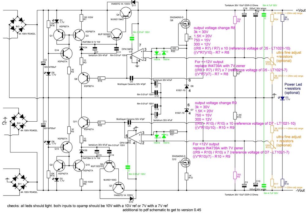

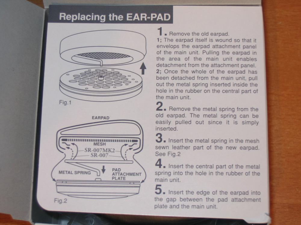
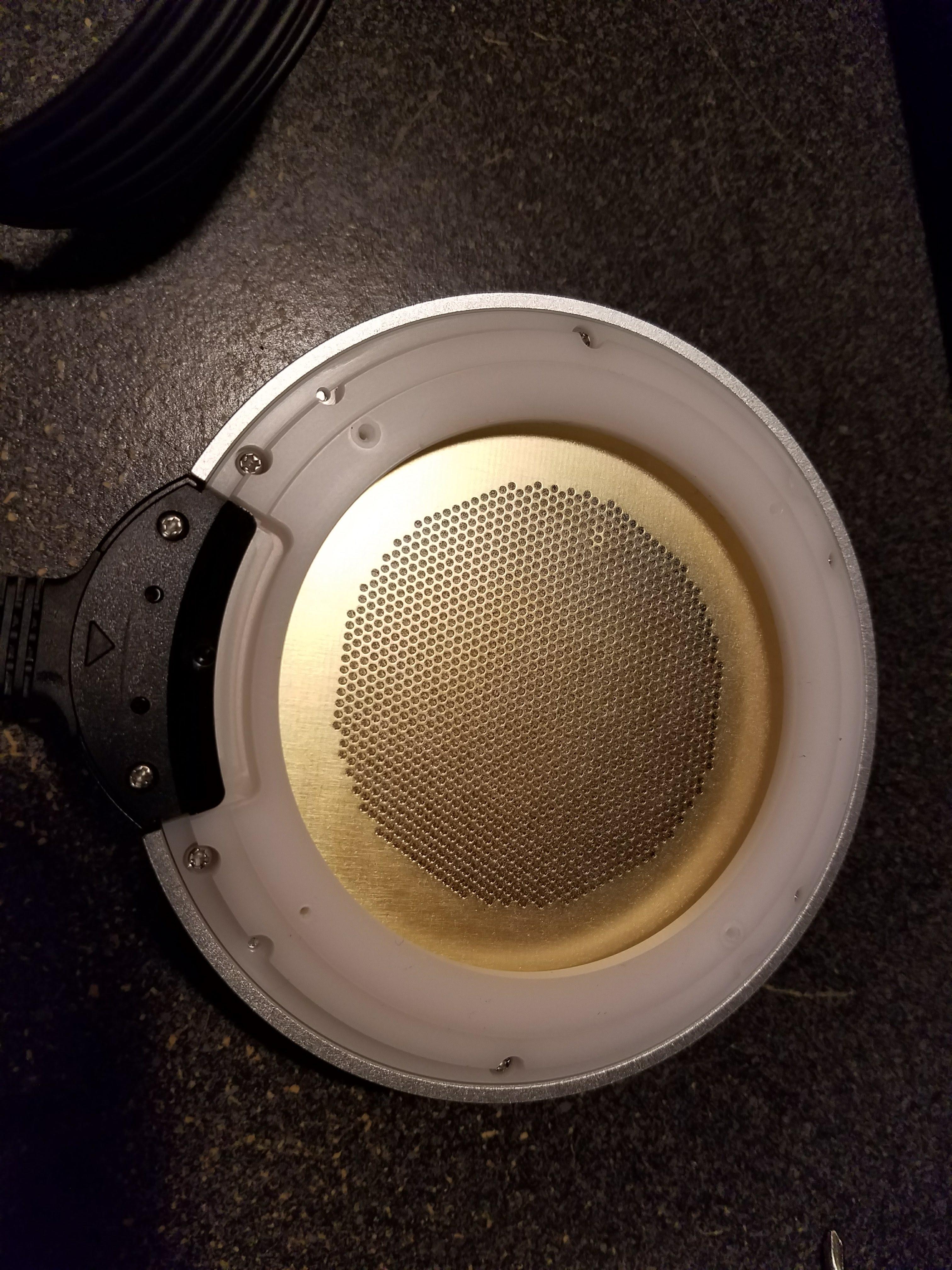
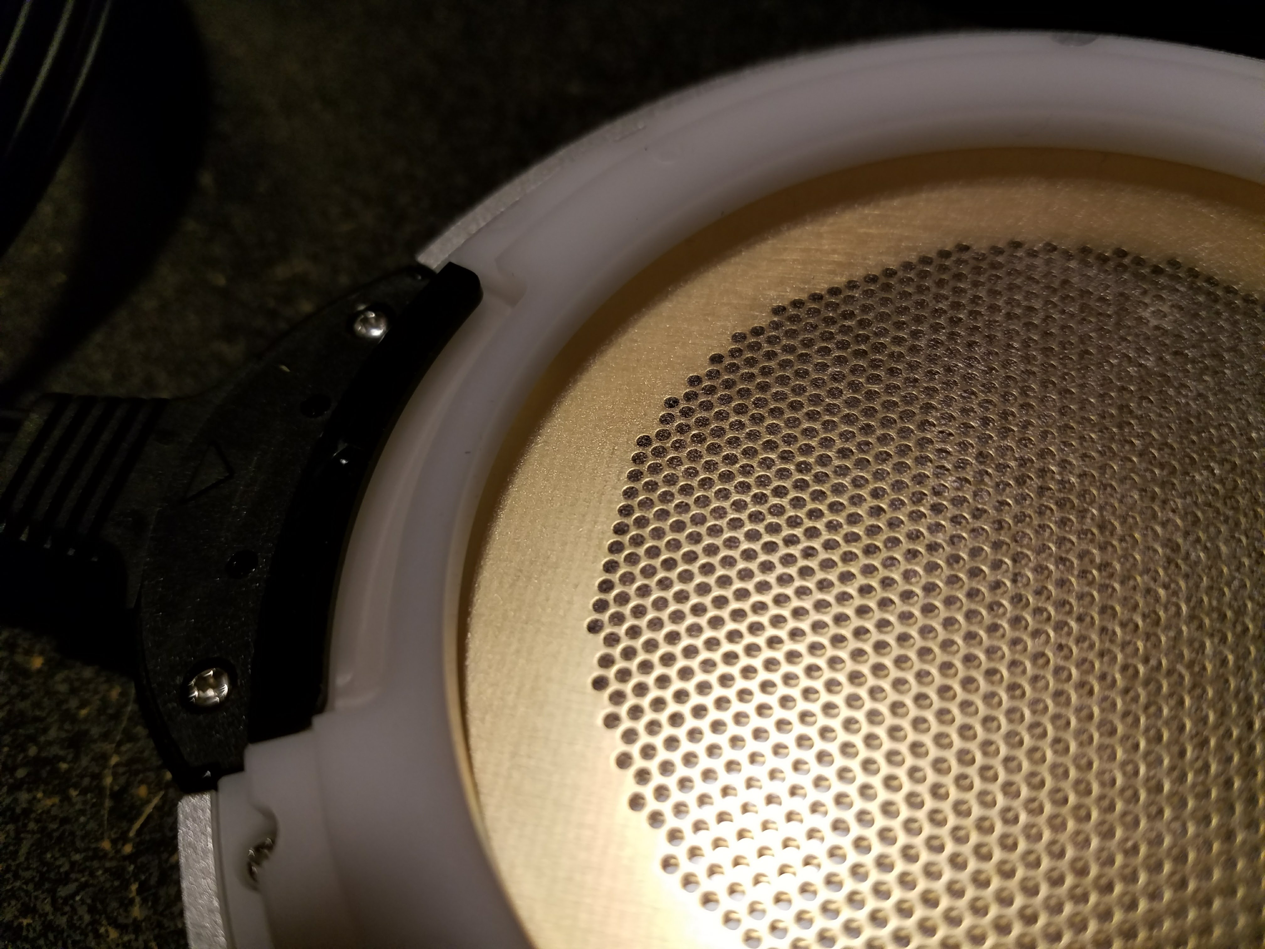
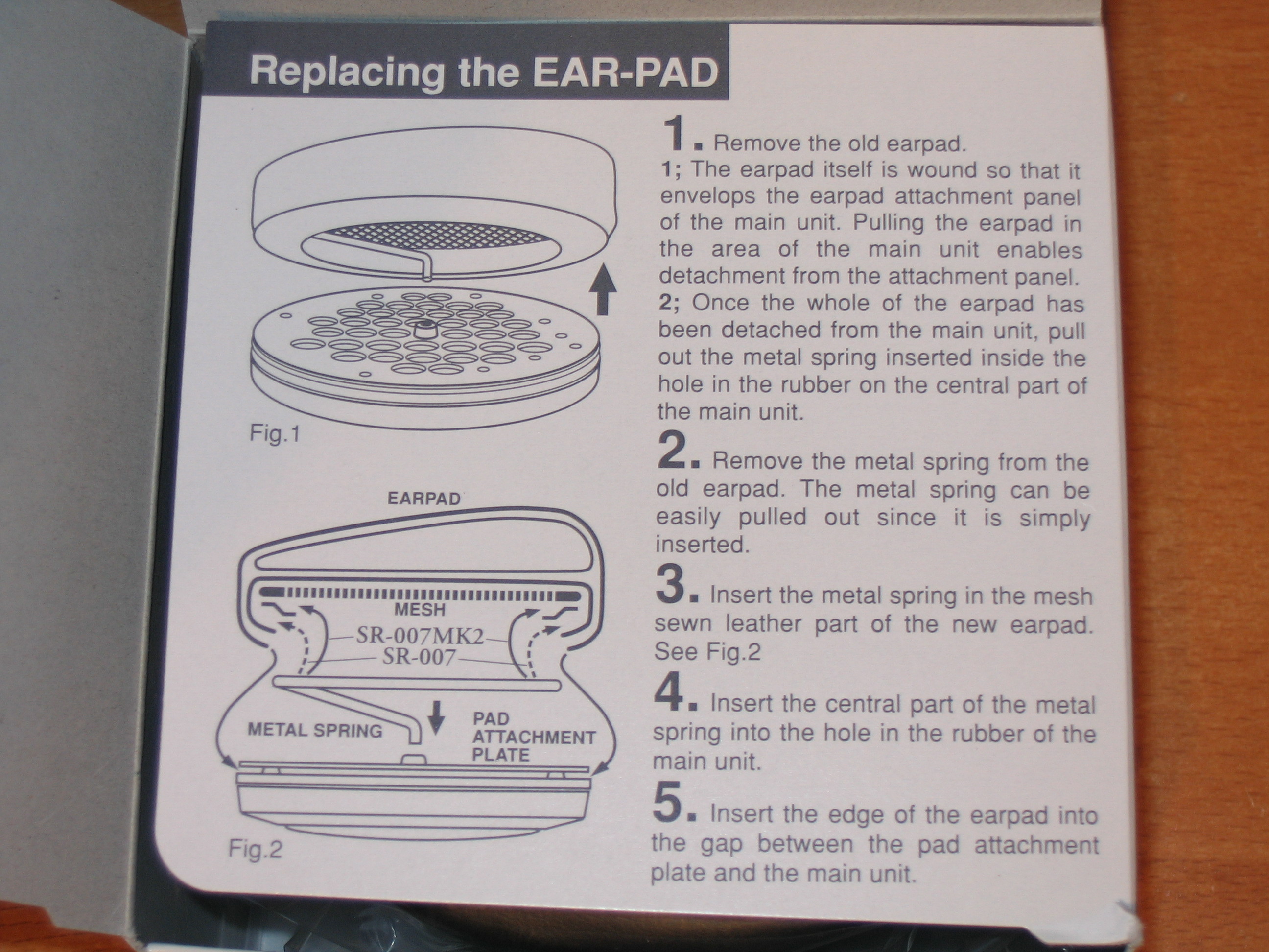
 1 point1 pointI know this will be very un-HC of me, but balanced DAC's have generally been more trouble than they are worth for me, especially when used with a balanced amp. It really comes down to what headphones you are driving and how much voltage swing you need, how much gain your amp has, and what sort of attenuator you're working with. If you get a hot source, with a high gain amp (I know the GSX has a switch), and sensitive cans you may just drive yourself crazy (pun intended). So careful what you wish/ask for and best of luck in your search.1 point1 pointI know this is an old topic, but I wanted to add some pictures of the latest sr-007 so that people can see if there are any differences. I did the blue-tac mod on the port and increased the spring to 105mm and flattened it as recommended. I inserted the spring as per the old -007 model as shown in the instructions (credit to spritzer for the instructions sheet picture). The difference in bass was actually quite moderate. It did help with bass response, but the change was subtle. Which is really all I wanted. No issues with the Stax fart at all so far. See attached. This was purchased Dec 15 2017 directly from Stax in Japan.

 1 point


Important Information
By using this site, you agree to our Terms of Use.
Account
Navigation
Search
Configure browser push notifications
Chrome (Android)
- Tap the lock icon next to the address bar.
- Tap Permissions → Notifications.
- Adjust your preference.
Chrome (Desktop)
- Click the padlock icon in the address bar.
- Select Site settings.
- Find Notifications and adjust your preference.
Safari (iOS 16.4+)
- Ensure the site is installed via Add to Home Screen.
- Open Settings App → Notifications.
- Find your app name and adjust your preference.
Safari (macOS)
- Go to Safari → Preferences.
- Click the Websites tab.
- Select Notifications in the sidebar.
- Find this website and adjust your preference.
Edge (Android)
- Tap the lock icon next to the address bar.
- Tap Permissions.
- Find Notifications and adjust your preference.
Edge (Desktop)
- Click the padlock icon in the address bar.
- Click Permissions for this site.
- Find Notifications and adjust your preference.
Firefox (Android)
- Go to Settings → Site permissions.
- Tap Notifications.
- Find this site in the list and adjust your preference.
Firefox (Desktop)
- Open Firefox Settings.
- Search for Notifications.
- Find this site in the list and adjust your preference.