

Leaderboard
-
Voltron
High Rollers29Points34514Posts -
swt61
High Rollers22Points22243Posts -
cetoole
Manufacturer/MoT19Points5454Posts -
MexicanDragon
High Rollers18Points8365Posts


Popular Content
Showing content with the highest reputation on 02/28/17 in all areas
-
8 pointsSo my son Andrew has been accepted to his 4 top schools, with great merit from 2, OK from 1, and we were waiting to hear from 1 (Clarkson, his top choice). Clarkson Financial letter came today, and at first it was disappointing, showing a decent but 3rd lowest amount in 2017, same in 2018, and then nothing beyond. THEN, we read more closely: FALL of 2017 and SPRING of 2018..... It turned out to be the highest of all the schools so far for a year, renewable for the 3 additional years as long as he maintains grades. WOOOOOO-FUCKING-HOOO are we psyched!!! The Hermit Boy even agreed to go out to a celebratory dinner with us So fucking proud.....he did this.....had some help to coordinate, but he did it.....8 points
-
6 pointsWent out for Chinese food with the Boston members of my family. My aunt Ju's mother was also visiting from Malaysia, and ordered everything, which was entertaining. Missing a few things, but it was all scrumptious. Definitely beat lunch, which was an airport salad.6 points
-
4 points
-
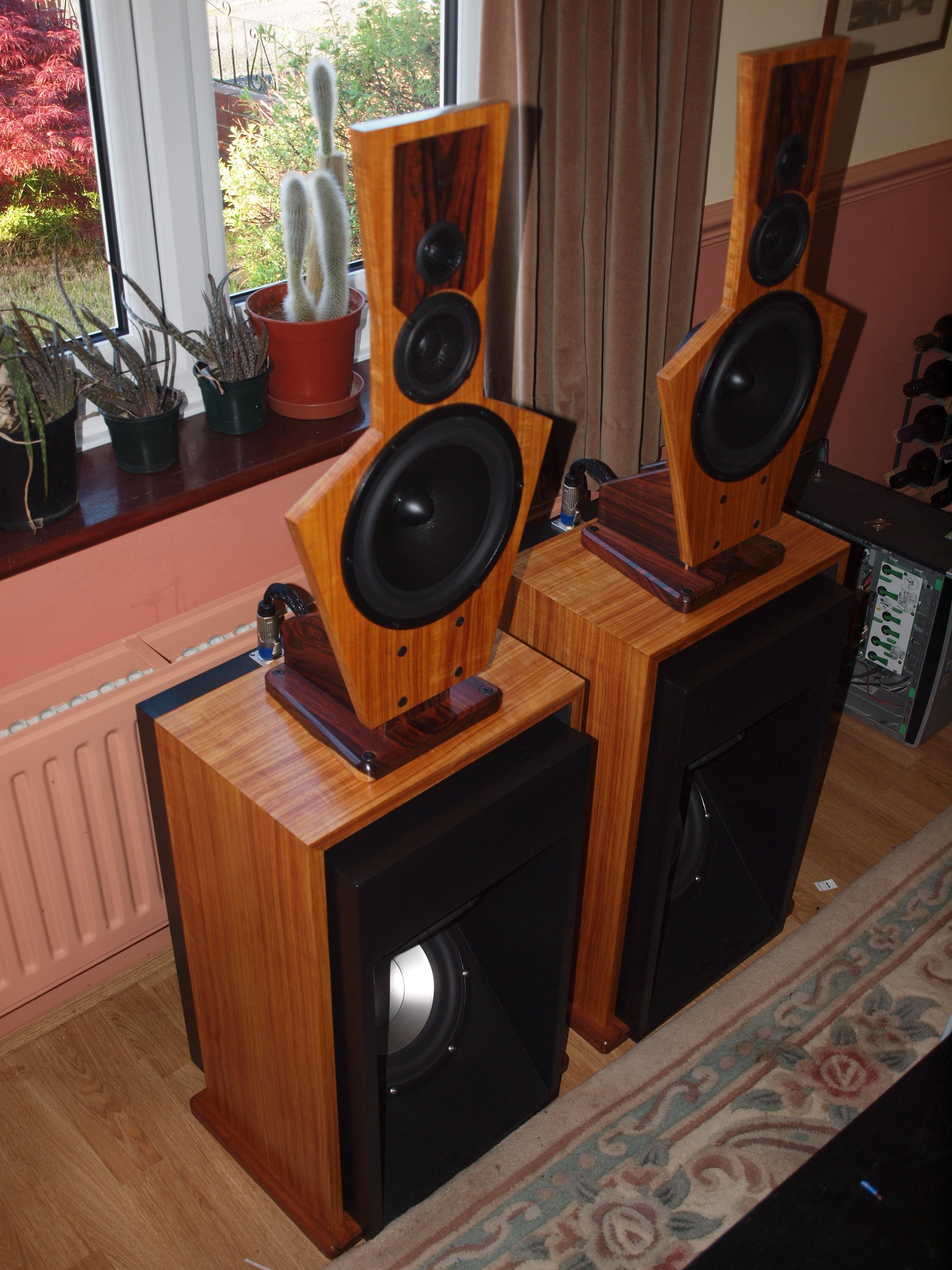
4 points3 points2 points2 points2 points2 points2 points1 pointfor 15V, have to recalculate the values of the 1M resistors. So one of them would need to be 473k1 point1 pointmight be stretching it a bit ... the two 1Meg + trim is really only needed if you care about mV accuracy ...you can omit those1 point1 point1 point1 point1 point1 point1 point1 point1 point1 point1 pointi saw a USED 100uf+100uf/500v black gate sold for $549 i should have bought a stock of retirement caps1 point1 point1 point1 point1 point1 point1 point1 point1 point1 pointCongrat to Andrew and congrat to his parents! Clarkson has become a hot school lately so that is an accomplishment.1 point1 point1 point1 pointOpen baffles do things box speakers don't. Of course they need extensive EQ, but one of the things you notice if you are used to box speakers is they can sound bass-shy. If you are used to open baffles, or electrostatics, of planar magnetics (Like Magnaplanar) there are no surpises. The bass is there in the right proportion to the rest of the music with no overhang, and sounds tight and fast. And open baffles interact with the room in a completely different way, exciting far fewer resonances. Well you can buy a kit, or even buy one already built. Or you can do what I did - buy two sheets of Baltic Birch and build them from scratch. Then hot hide glue veneer them, and French polish them. Parts which are not veneered I made from a Rosewood called Cocobolo, and the feet were made from Goncalo Alves.
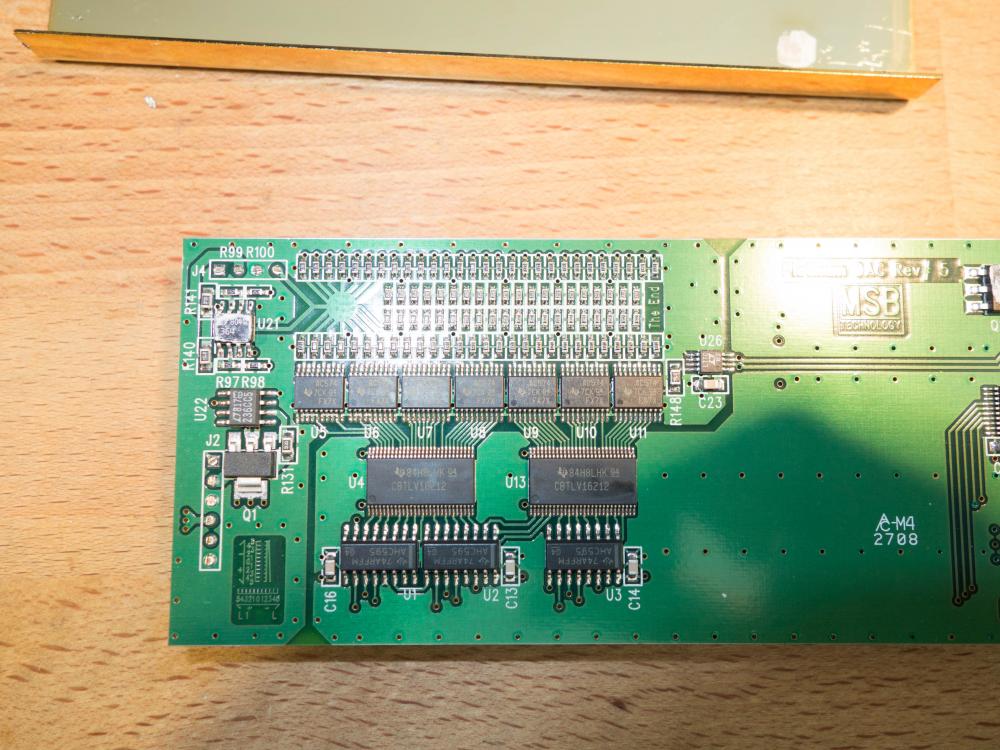
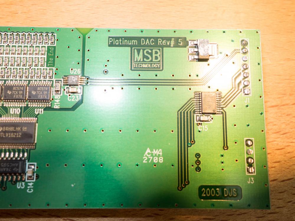
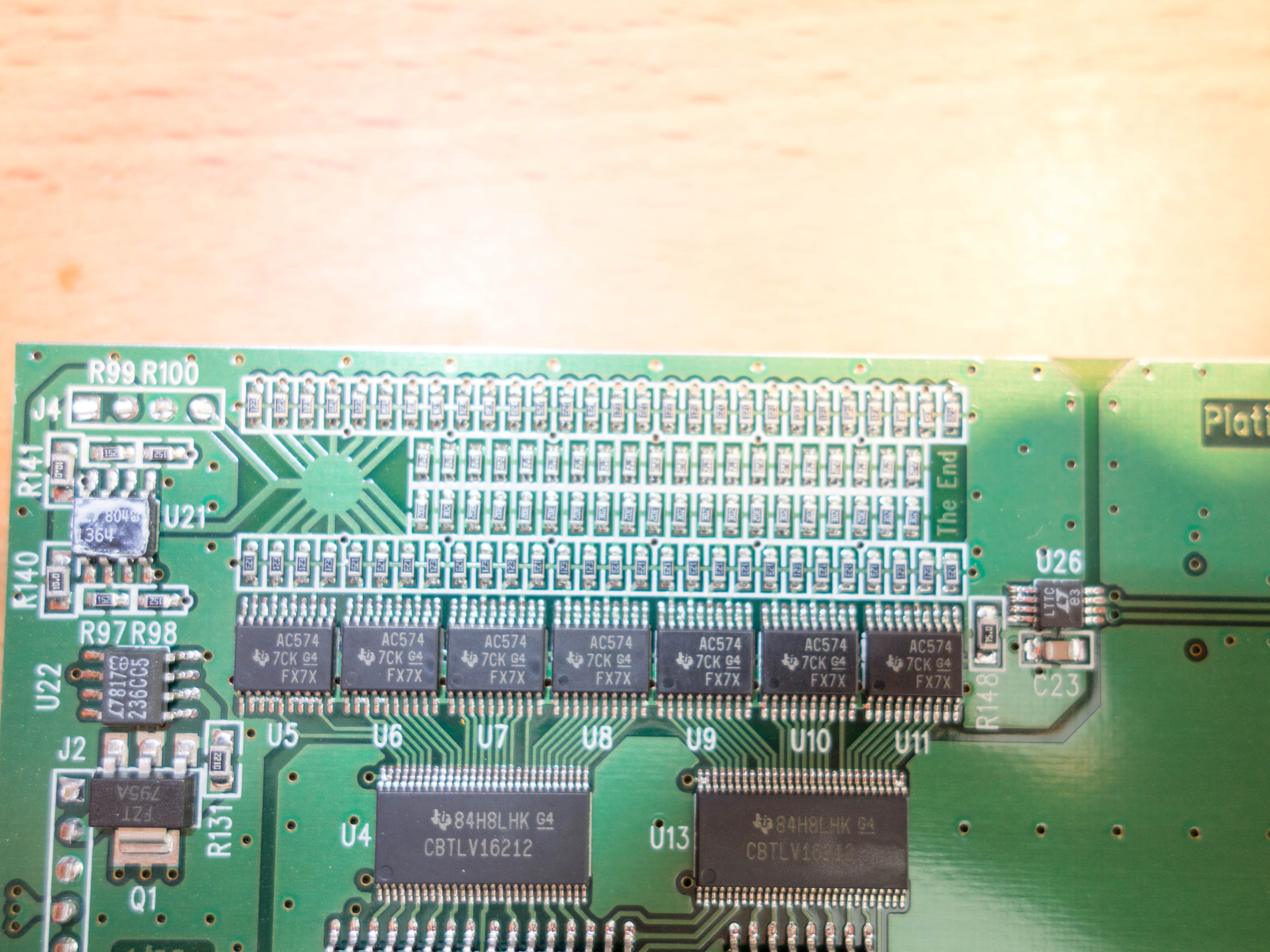
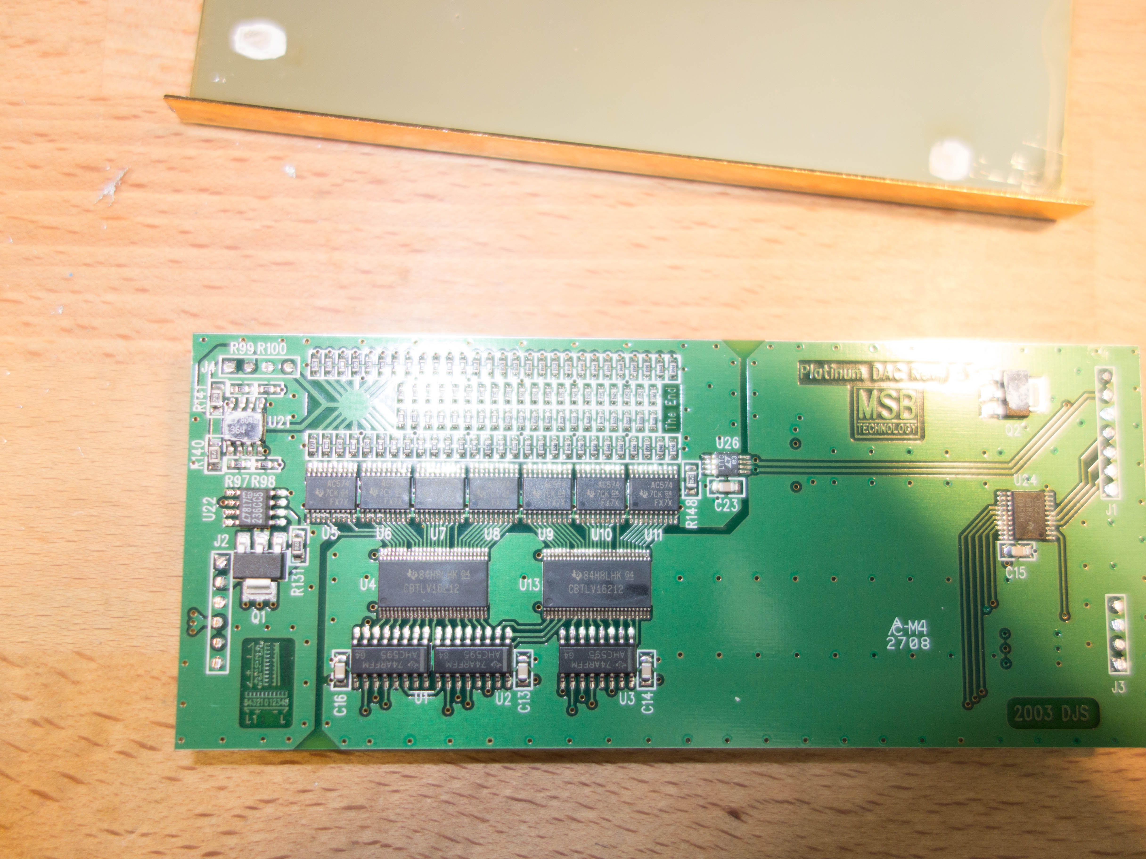
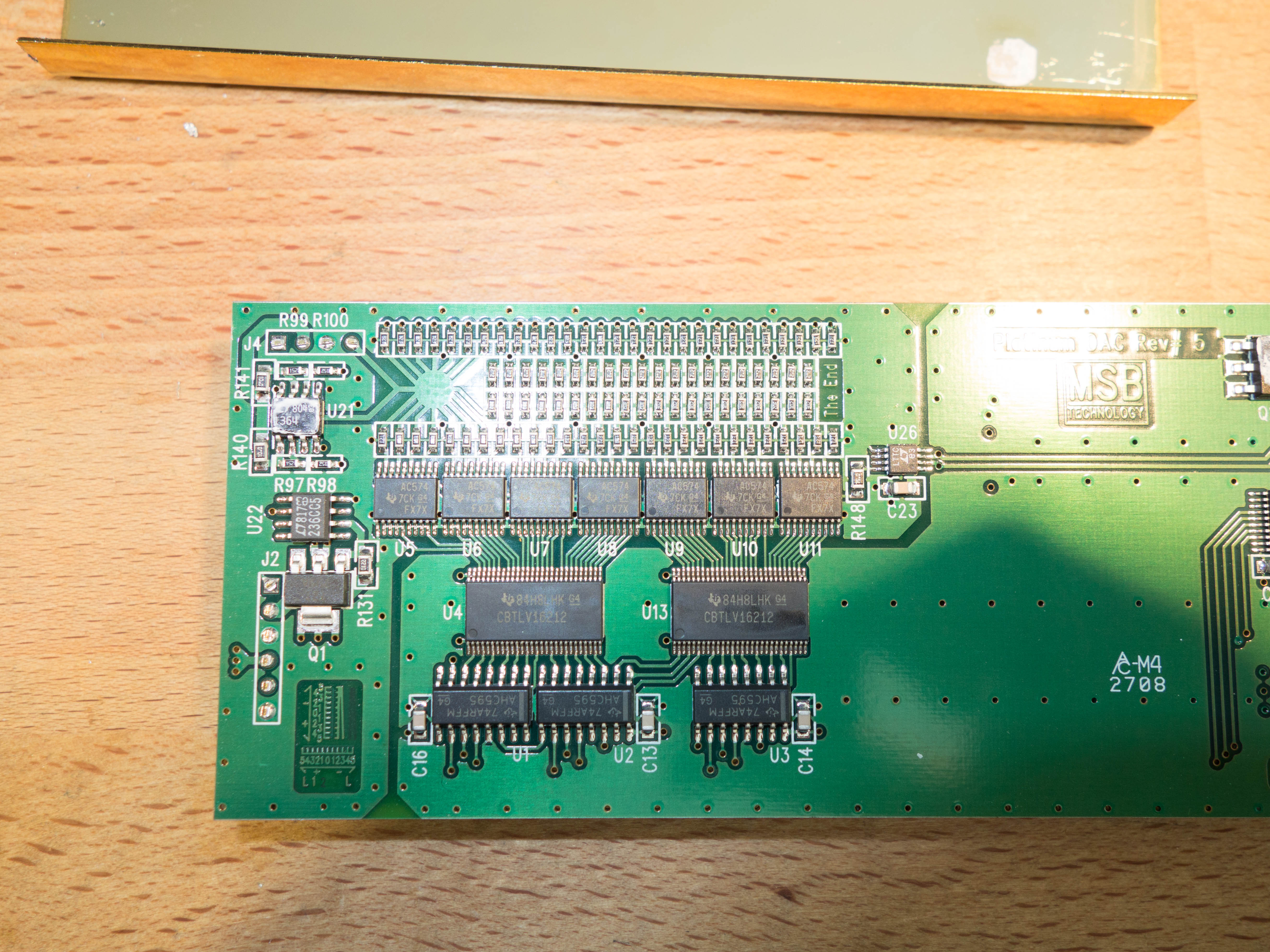
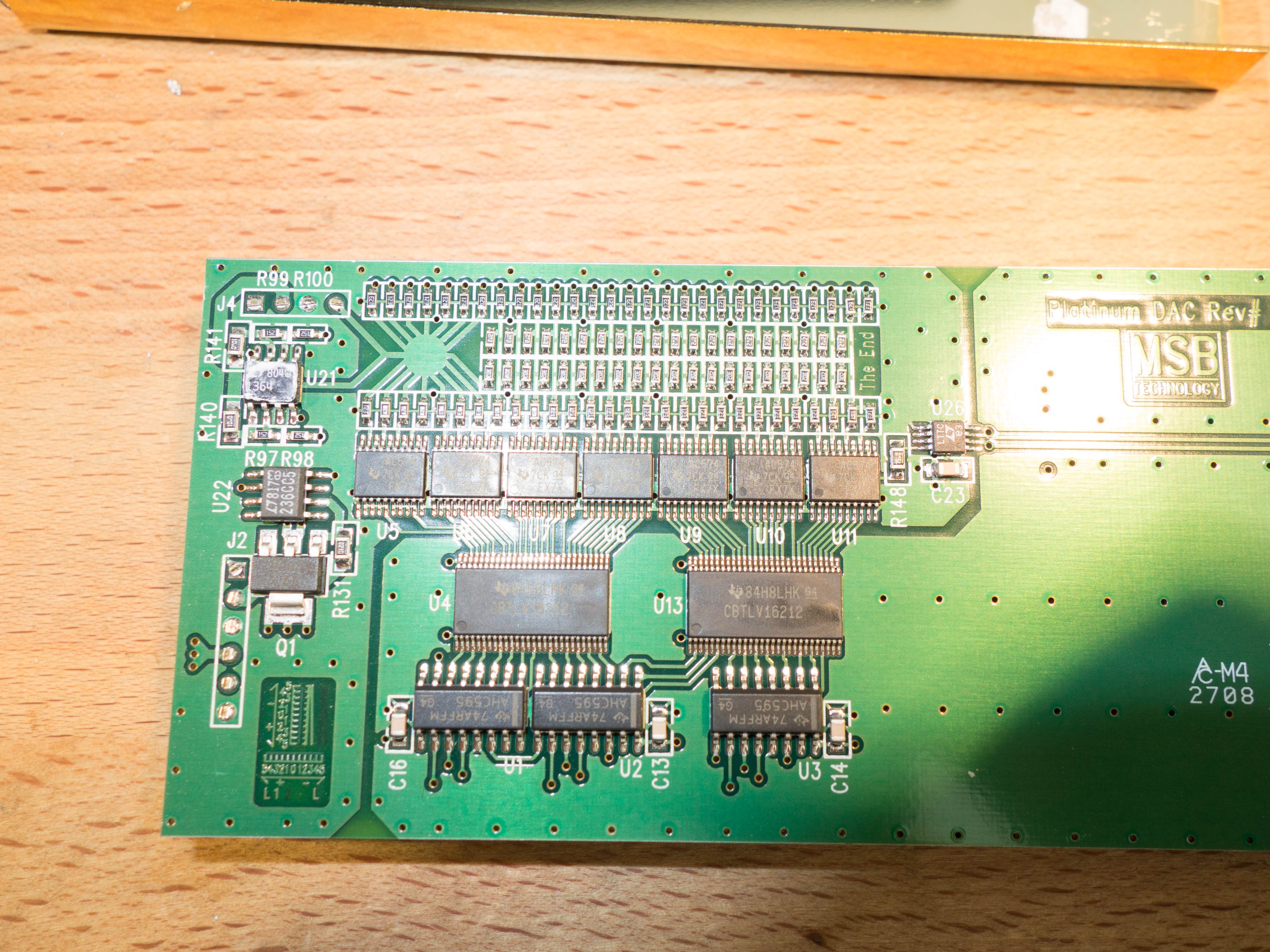
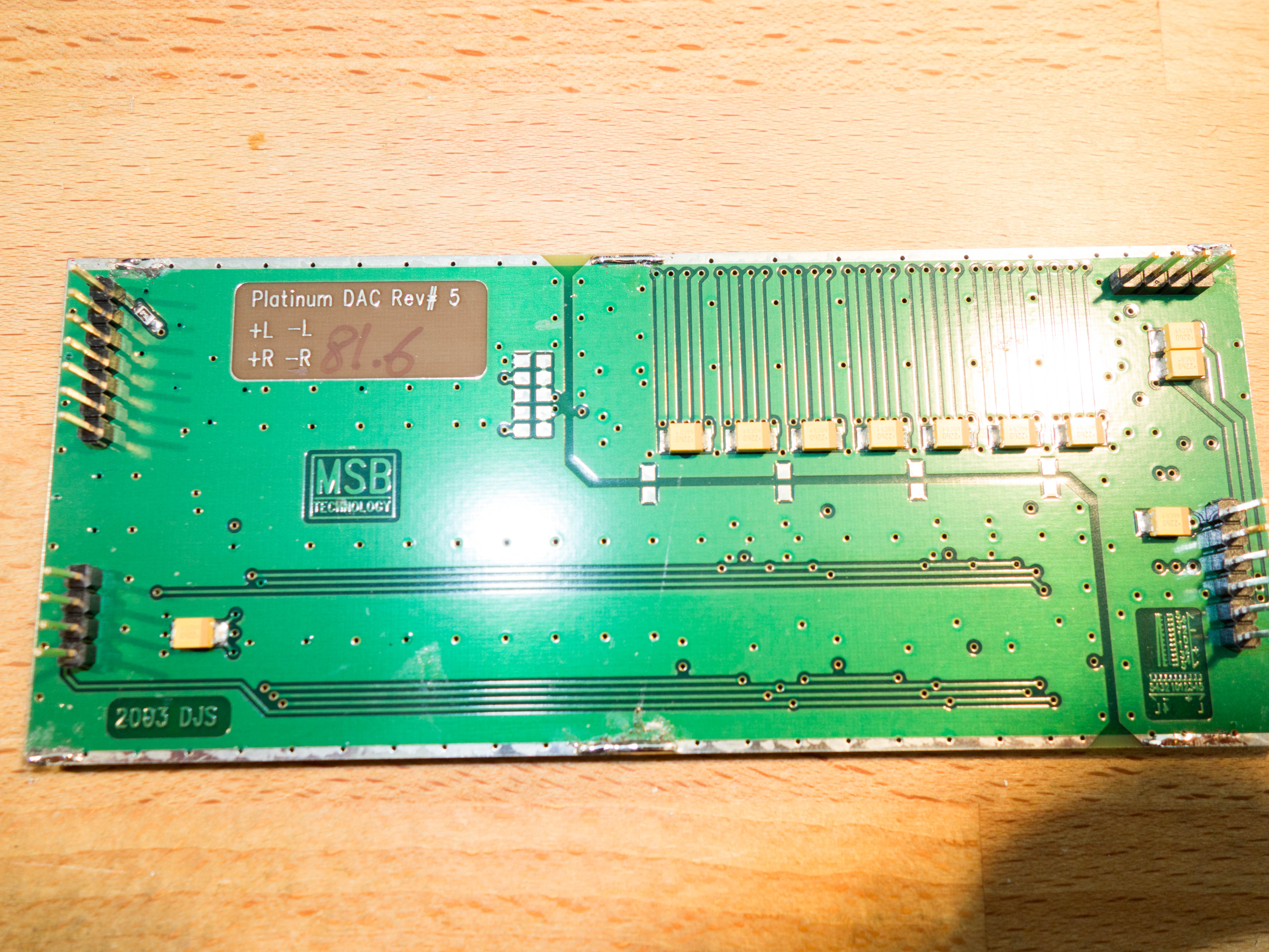
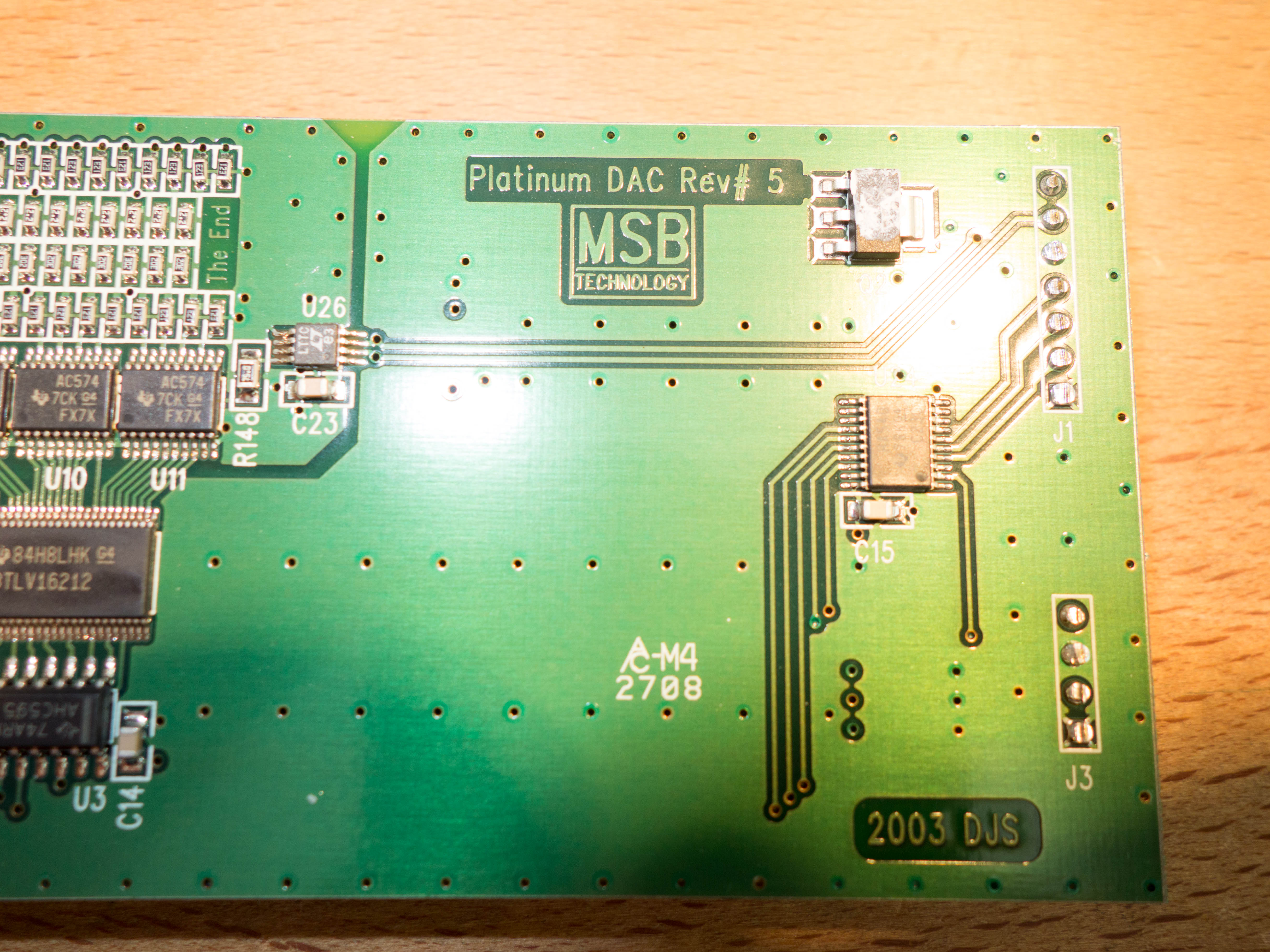
 1 pointI was pulling the MSB out of my system and here is inside one of the dac modules. The cover was simply soldered in place which the Metcal simply laughed at...
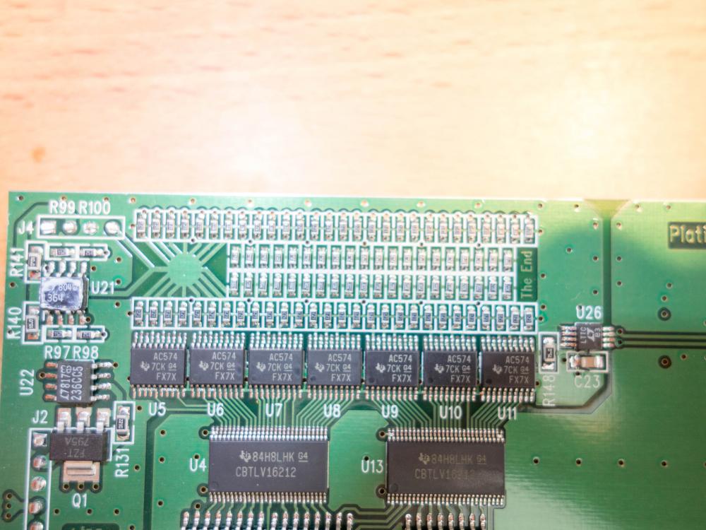


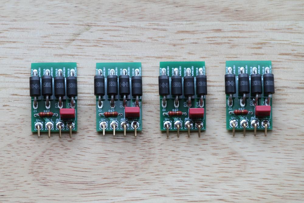
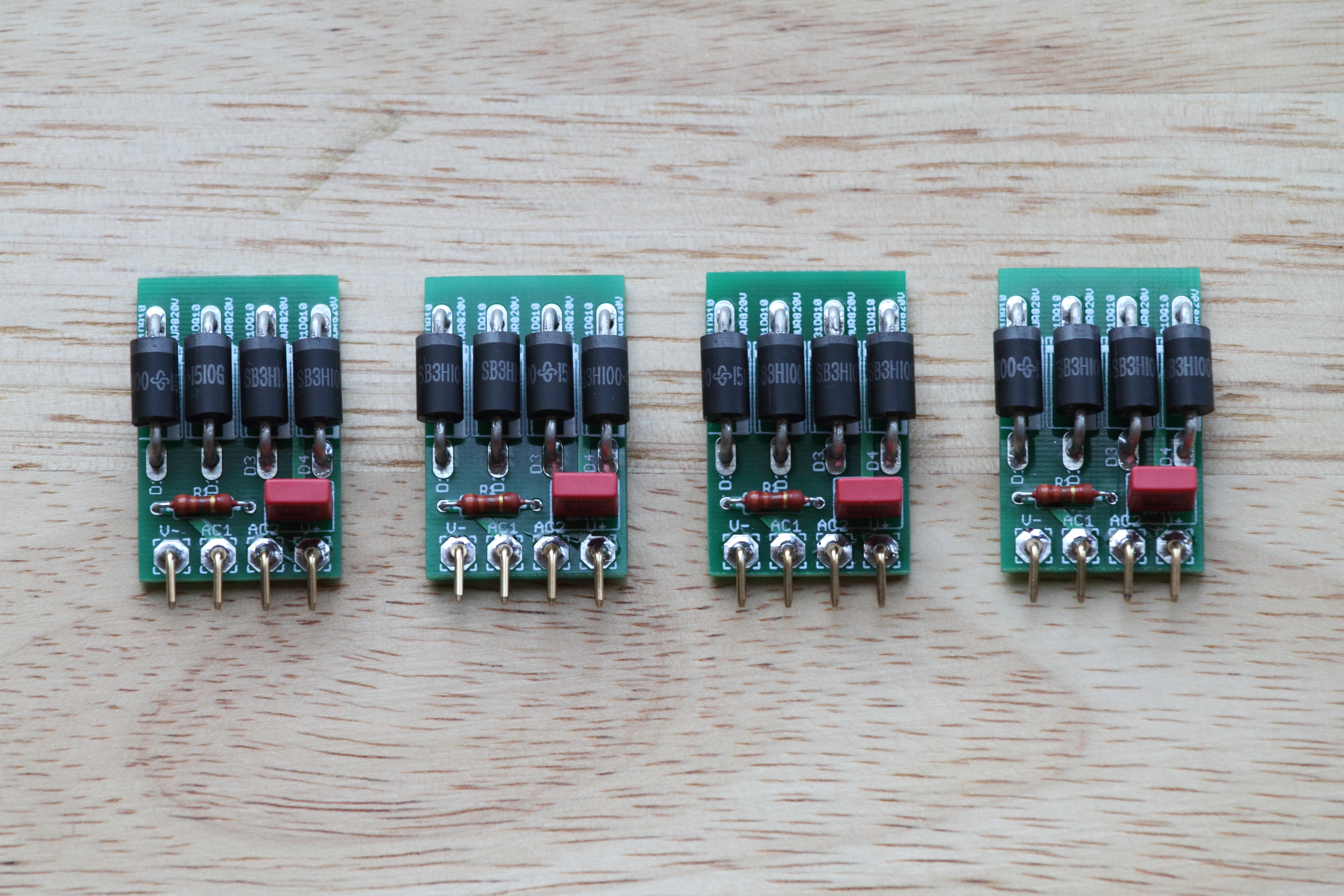
 1 point1 pointMy Numark did have its original paper receipt and the date was early 1974, also it seems it was sold for about $59.95 back in 1973 based off this copy of an advertisement so the dates do sort of match: https://books.google.com.au/books?id=GgkEAAAAMBAJ&pg=PA58&lpg=PA58&dq=numark+es-701+headphones&source=bl&ots=zGAGhTDWYQ&sig=kaOZzaC6nYyZX266P4HHIaHxs0Y&hl=en&sa=X&ved=0ahUKEwjmzYLU7KzSAhVJwbwKHX5fCC0Q6AEIRTAJ#v=onepage&q=numark es-701 headphones&f=false Have never seen any form of real life pictures of the SE-1000 just Pioneer ad pictures floating about online. The Napolex and Elega electrostatic headphones also are on my look out list. I missed out on a local ebay Elega CR-2074C last year which sold for $150'ish. Anything Elega and Napolex is extremely scarce and rare. The early Napolex units are possibly SR-3 - SR-5 clones drivers and baffle wise in construction but the design is slightly different. I have been on the hunt for the Toshiba electret which I've only seen Birgir own and posted pictures of here many moons ago. There is also the Technics EAH-80 that is quite interesting: http://20cheaddatebase.web.fc2.com/TECHNICS/EAH-80.html Elega http://20cheaddatebase.web.fc2.com/elega/CR-1070C.html http://20cheaddatebase.web.fc2.com/elega/CR-2072C.html http://20cheaddatebase.web.fc2.com/elega/CR-2074C.html Napolex http://20cheaddatebase.web.fc2.com/napolex/ES-100.html http://20cheaddatebase.web.fc2.com/napolex/EX-1.html http://20cheaddatebase.web.fc2.com/napolex/NSA-3.html There are possibly more other unique electret/electrostatic models floating about that never saw the light out of Japan as they are domestic models and its evident that most big Japanese brand manufacturers had some electret or electrostatic headphone in there product lineup. Designs and rebadged models can be traced to Elega, Stax, Pioneer and Audio Technica. Sony is about the only company that never did OEM copies of the former mentioned manufacturers, shame Sony today is not what it was back in the 1960-90's. The SE-1S and its matching EE-1 adapter? Fairly average sounding I'd put them just a bit below the SR-3N in terms of fidelity (resolution, soundstage, treble, mids, highs and bass), the comfort is quite shit though as the headband clamps fairly tightly to your noggin' if you have a big head.1 point1 point1 pointAnother two GRLV live! These are set up for 20VDC rails to power my dual-mono SS Dynalo. Thanks to Pars for his creation and generosity of sharing the Schottky bridges with a built-in AC snubber. Although I have to settle for the LM4040 VREF for now until I get the LT1021.
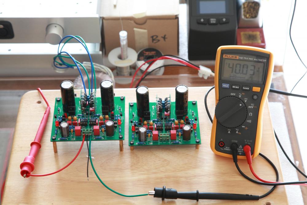
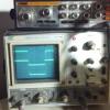
 1 pointHere's my mouser list. It includes resistors for 15, 20, and 30V. No voltage reference chip. I ordered those direct from linear, it was cheaper than Digikey. http://www.mouser.com/ProjectManager/ProjectDetail.aspx?AccessID=fba137c1691 pointWas playing around with input voltage and looking at dropout. This doesn't drop out of regulation untli input is ~16.8Vac or so (output is still at 19.95Vdc). DC at the filter caps is ~22.7Vdc at that time (IIRC). I thought it would drop out before that. This is completely unloaded. I think I will go with the 20V transformer, as Michael suggested. Even at 24Vac input, pass devices were not warm, though I'm sure that will change when it is loaded. EDIT: trying to recall, do most builders tie the AC ground to the PSU or amp board grounds, or just to the chassis? Don't any RCA connectors, etc. in effect tie the board ground to AC ground/chassis? I know that XLRs wouldn't.1 pointOh all right... with std. rectifiers With Schottky bridges One other thing I noticed while playing around with this. Since this is just on a piece of wood, I don't have the AC ground tab connected to anything. When checking AC voltage between it and the board ground, it was floating around at 50-60Vac. I assume this is normal since the board isn't really referenced to anything? Should I tie the AC ground tab to the board, either directly or thru the 10 ohm resistor that is provided?1 pointI used 581-TAP476M020CCS on six or so units and 35v for the 10uf 581-TAP106K035SCS from the semantic it looks like they only see 10v C8 & 9 are fed by the lt1021-10 C7 & C13 are in parallel with a 9.1v zener and C16 & C3 go rail to the voltage divider/ inverting input, which is also 10v I remember wondering about that 20v part too. so far no problems with them, using 20v to 40v output1 pointC7, C8, C9, C13 for the 47uf C3, C16 for the 10uf Assume a supply setup for +/-20V output, 2x23VAC input1 pointThanks for your posts guys. My question was a leading one in an attempt to have simple and direct parts list for builders that may be very skilled in building equipment but may not have a high level of understanding of schematics or circuits. I was hoping someone would come up with a little table like the following. ((R8 + R7) / R7) x 10 ((1.5 + 1.5) / 1.5) * 10 = 20v ((2.21 + 1.5) / 1.5) * 10 = 24.7v ((3 + 1.5) / 1.5) * 10 = 30v R7 = 1K5 R8 = 1K5 for 20V R8 = 2k21 for 24.7V R8 = 3K for 30v R9 = R7 R10 = R81 pointPost it again for reminder for V+: (R8 + R7) / R7 x 10 (reference voltage of D5 - LT1021-10) for V-: (R9 + R10) / R10 x 10 (reference voltage of D7 - LT1021-10) congo5's way is also right assuming that you have fixed R7,R10 's value.1 pointwhat voltage do you want? I do not understand Kevin's method so came up with this: desired voltage x 150 -1500 = R8, R9 40v is 40 x150=6000 -1500=4500 30v is 3kR 25v is 2250R1 pointDamn, I already populated all 3 bridges. Should I remove the middle one or just leave it there?1 pointNoob style question - how is the latest board transformer wired? I'm using a dual secondary transformer, so I'm assuming I wire the two AC lines and leave the center GND open. Also, what's the 6th input to the side with resistor to ground for used for?1 pointI think I used an Antek AS-0520 with the GR for my friend's SUSY Dynalo build. It's rated at 1.3A. I bolted the pass transistors to the chassis and it worked very well. Although I see it's out of stock at the moment. The GR single board version offers more flexibility in chassis layout but requires one to use dual secondary transformers. I cannot think of other advantage/disadvantage personally but others may chime in.1 pointOkay, it's nice to know I can go down to 20VAC. I am thinking of using a 50VA 2 x 22V antek transformer. http://www.antekinc.com/as-0522-50va-22v-transformer/ It says the current is 1.1A at 22V but the datasheet they have says it can go to 3A under differing loads so I am not too concerned about current handling. If I am cutting it too close on the current I could go to the 100VA version but that seems to be overkill. For the boards I see there is a goldenreference6 single board and a goldenreference7 dual board. Is there any particular advantage to using dual boards vs a single board?1 point1) 35V 581-TAP476M020CCS don't have a link for the 10uf 2) does not matter I used these 810-FK28C0G1H470J 3) I used these 505-MKS2-4.7/50/10 which are in stock and 50V, more than enough 4) I used these 505-MKS2.01/63/101 point


Important Information
By using this site, you agree to our Terms of Use.
Account
Navigation
Search
Configure browser push notifications
Chrome (Android)
- Tap the lock icon next to the address bar.
- Tap Permissions → Notifications.
- Adjust your preference.
Chrome (Desktop)
- Click the padlock icon in the address bar.
- Select Site settings.
- Find Notifications and adjust your preference.
Safari (iOS 16.4+)
- Ensure the site is installed via Add to Home Screen.
- Open Settings App → Notifications.
- Find your app name and adjust your preference.
Safari (macOS)
- Go to Safari → Preferences.
- Click the Websites tab.
- Select Notifications in the sidebar.
- Find this website and adjust your preference.
Edge (Android)
- Tap the lock icon next to the address bar.
- Tap Permissions.
- Find Notifications and adjust your preference.
Edge (Desktop)
- Click the padlock icon in the address bar.
- Click Permissions for this site.
- Find Notifications and adjust your preference.
Firefox (Android)
- Go to Settings → Site permissions.
- Tap Notifications.
- Find this site in the list and adjust your preference.
Firefox (Desktop)
- Open Firefox Settings.
- Search for Notifications.
- Find this site in the list and adjust your preference.