

Leaderboard


Popular Content
Showing content with the highest reputation on 09/10/20 in all areas
-
9 pointsWork has been slow today, did the update. There are issues with the dark theme which I'll get to.9 points
-
9 pointsI didn't feel like starting another new thread, there's a major version update of the forum software that's available. It's nearly a complete redesign so not a simple maintenance release. Currently planning to do this sometime Friday afternoon or evening.9 points
-
8 pointsThe haze cleared long enough to get a view of Mt Tam this afternoon.
 8 points
 -
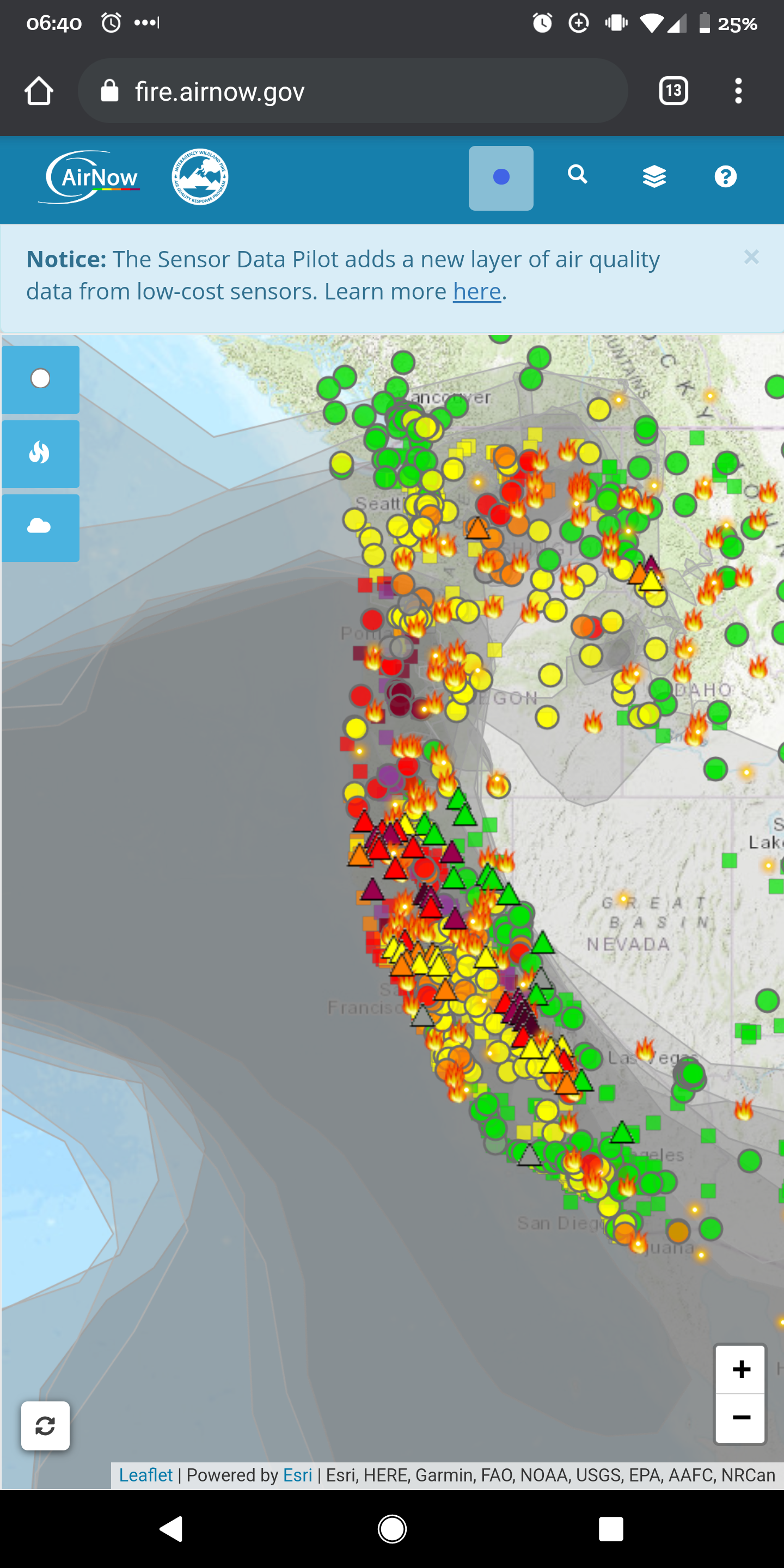
5 pointsAdding to the apocalypse documentation. Approaching noon in Mtn View. Was brighter after sunset. Keeping on eye out for boils tomorrow.
 5 points
 -
This new editor is kinda weird. More like 3, but who's counting? Raymond Loewy design for Studebaker "Wagonaire" with retractable sliding rear roof section, 1963. Also, Imgur informs me that I've been on the site for 10 years as of yesterday.4 points
-
4 points
-
4 pointsMy theory is that Trump has ordered his spray tan dumped in the upper atmosphere. Hoping that it turns California residents Orange, in a false show of unity.4 points
-
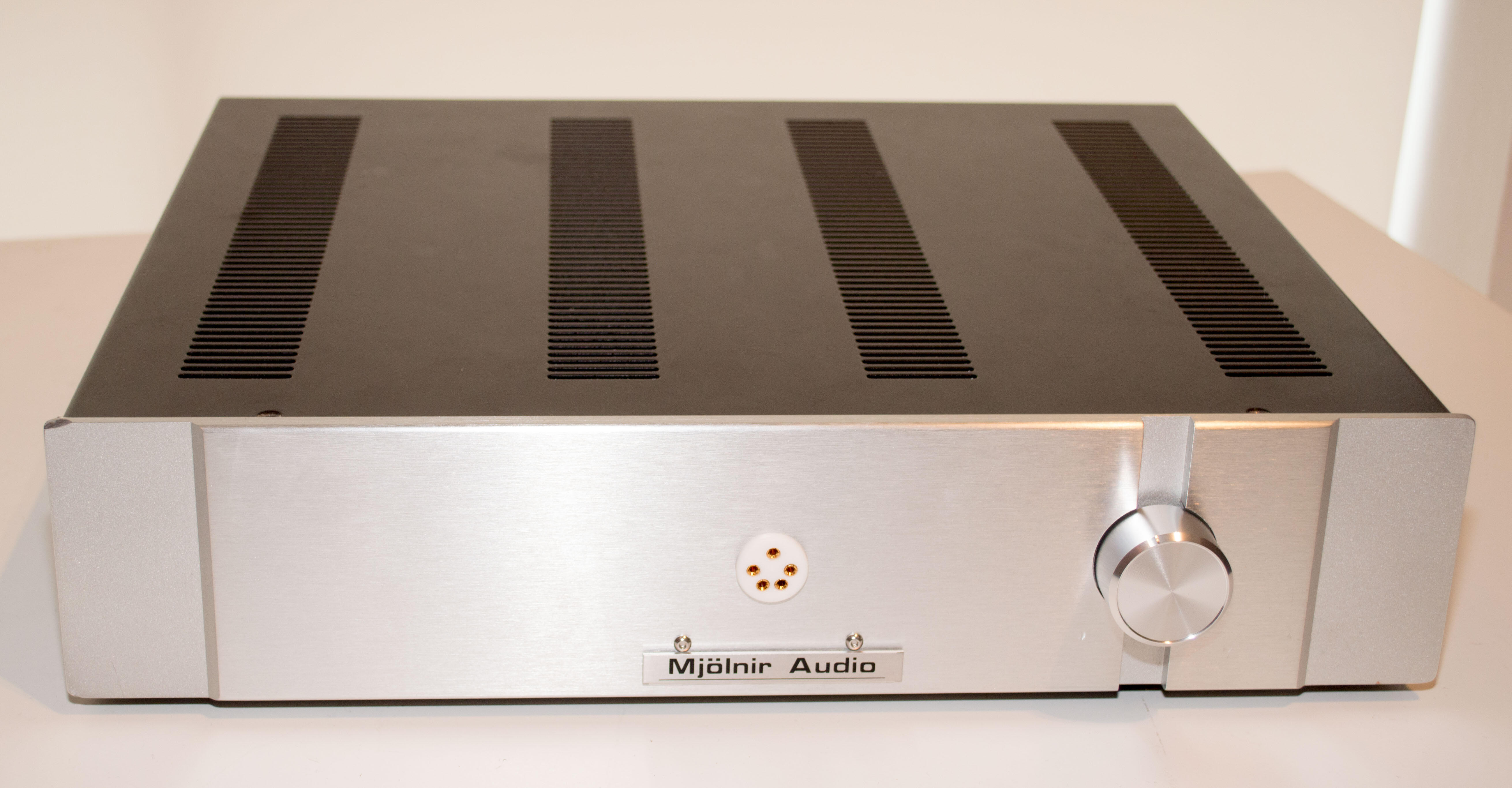
4 points4 points4 pointstry not to kill the user until AFTER they have finished paying for it Equal rights for electrons! they should be allowed to travel freely and not be constrained by insulation... If they want to travel through your heart it just their way of being loving and friendly.... they are so misunderstood.4 points4 pointsAs always, thanks Todd. Please let us know if there's any way to contribute to the ongoing costs of keeping the lights on.4 points3 pointsThe dark theme needed a swift kick in the ass, the menu pops up correctly with it now.3 points3 pointsRIP Diana I for one was totally in love with her and dreamed of a Lotus Elan just because of her.3 points3 pointsNeither do I, so I listen to those who do. I suppose the other approach is to just not care about things you don't understand.3 points3 points2 pointsThis is now fixed in the dark theme. New forum software version + clean install of the theme did the trick.2 points2 pointsRIP Dame Diana who was quite a dame. And fuck cancer (even though she smoked half a million cigarettes in her life).2 points2 pointsTapatalk is officially dead and will no longer work properly. Nevermind, Tapatalk should be working again for anyone still bothering to use it.2 points2 pointsThere's a guy in here named Steve that should make a joke about this.....2 points2 points2 points2 points2 pointsNYC Sunset Sept. 5, 2019, 7-50 PM. There was a zoomer meme going around last month about "Zucc kinda thick tho." 1957 Snider TV Clock/Lamp.2 points2 points1 pointMy experience is that the balance servo is very efficient so 50 mV is expected. As for offset – 5K trimmer parallel with 510R resistor reduces highest emitter resistance to roughly 465 ohm which probably is too low. May I suggest replacing R73 (6.2K) with a 10K trimmer and keep R64 (510R) untouched? I have used that for a long time and it works great.1 point1 pointAbleton is kind of fun, but now that I bought the MBPs I am going to try Logic Pro and Luna.1 point1 point1 pointCould you imagine 15" in circumference? I sometimes have a hard time talking some into "it", at close to 1/2 of that. 😳 Anywho, back to home theater.1 point1 pointIf anybody is seriously considering 15", I've over inflated expectations.1 point1 point1 point1 pointRIP Diana Rigg, aged 82 from Cancer In her pomp: BBC obituary for Diana Rigg https://www.bbc.co.uk/news/entertainment-arts-279862721 pointfor these covid times...1 point1 pointHave I mentioned how much I love Gunship?1 point1 pointI am really excited about the Marantz NR1711! https://www.us.marantz.com/en-us/shop/avreceivers/nr1711 Pretty featured packed. Will be my third slim-line, following various updates they have made.1 pointFor Your Love – Chilly (Todd Terje re-edit)1 point1 point1 point1 point1 pointThis one came to an end this week as I finally got round to turning the amp on and testing it. Busy summer and all that but here is what this should have been in the first place: Old school KGSSHV build only using the input sockets on the back, that swanky gold IEC and the volume control. The rest was all garbage...

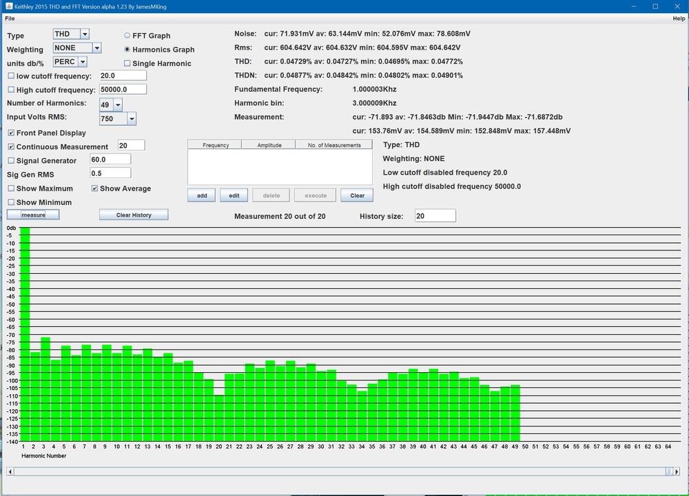
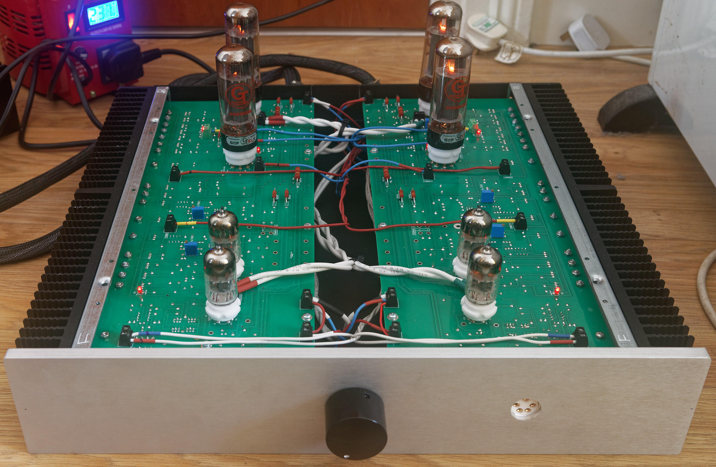
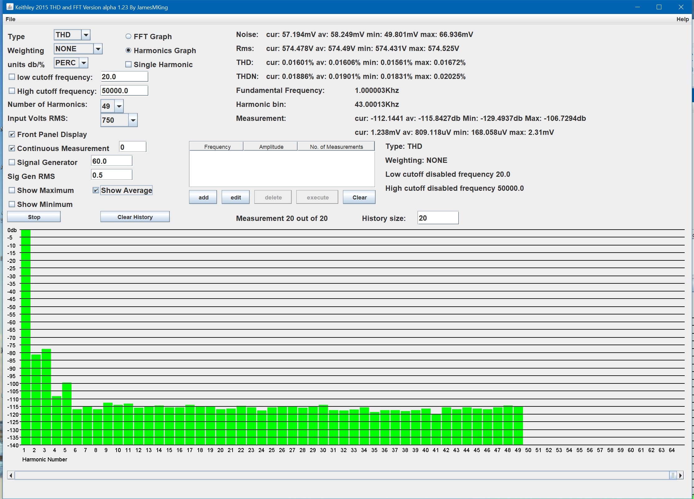
 1 point1 pointlisten to it? if you check my todo list nowhere does it say listen to it... measure it yes... listen to it? why would I do that? 🙃 latest update, internal signal wiring done (silicone not cardas - I need to buy more cardas chassis wire) and front panel completed. Both channels powered up at the same time for the first time. No drama so far. The heatsinks around the el34s runs a bit hotter than joamats mini T2. I not done any temperature checks look good. All transistors seem ok and so do the high power resistors. .6922 heater voltage is a little high at 6.35V so I will need to add some dropper resistors. All other voltages are spot on. El34 heaters are at 6.1V which is about the same level as my mini T2. I found my first issue, the DC balance between + and - halves of a channel is fine <50mv BUT the DC offset to ground started at -85V and even adjusting the offset pot all the way I only got it down to -33V. Exactly the same on the other channel due to close matching of components and matched valves. So I will need to replace the dc offset adjustment trimmers with something 2-3x the range. Anyway I know you have been waiting for the money shot: glowing leds and heaters so enjoy: Im currently going for an extended power on idle test and will be periodically checking voltages and temperatures on both the amp board and psu. If that passes it will be time to feed it some test signals... I hoping for more detail in the square waves, more dynamics in the triangle waves and smooth fatigue free sine waves. Here are the first measurements. Distortion 1Khz input Total Harmonic Distortion to 49Khz is around 0.0063% unweighted (average of 20 measurements) 2nd harmonic is around -90db and third slightly higher at -87db. The other harmonics are very low all less than -105db. total harmonic distortion plus noise is better than 0.018% (im not using shielded cables for this test AND the amp and psu do not have top lids and the cases are not grounded so the amplifier is almost certainly has better thd+n than I am measuring in this setup. At around 575V rms 5th harmonic starts to rise and at 600Vrms output all harmonis increase and odd order are higher than even order harmonics. NOTE this measurements where taken with around 35V DC offset so it is possible clipping may occur a little later with less offset... Noise, THD, THD+N and level of distortion harmonics at 575V RMS, 1Khz output: Noise, THD, THD+N and level of distortion harmonics at 600V RMS output 1Khz: The THD up to 49Khz is still less than 0.05% The amp runs quite a bit hotter than the mini T2, heatsinks near the EL34s run at 40C and power consumption is close to 205W. The mini T2 is around 153W. The power supply is also is less efficient than the golden reference HV, the 3W resistors between the ksa1156es and ksc5026 run close to 90C and dont have a lot of room around them, on one side there is a large 0.1uF 1KV film cap and on the other 5 closely packed transistors... So the T2 needs good heat sinking and the psu boards could do with lengthening a little to give the 3W resistors a little more air flow around them and drill holes under them. Update DC offset fix, The 5K pot in parallel with the 510 ohm emitter resistor gives a minimum resistance of about 461ohm which still gaves me ~ -33V offset. With the 5K pot in the middle you get around 423ohm combined resistance and ~ -85V offset. So I replaced the 510ohm with 604ohm and this gives enough adjustment range to get <1V DC offset. (I would have implemented joamats suggestion but I did not have any 10K pots)
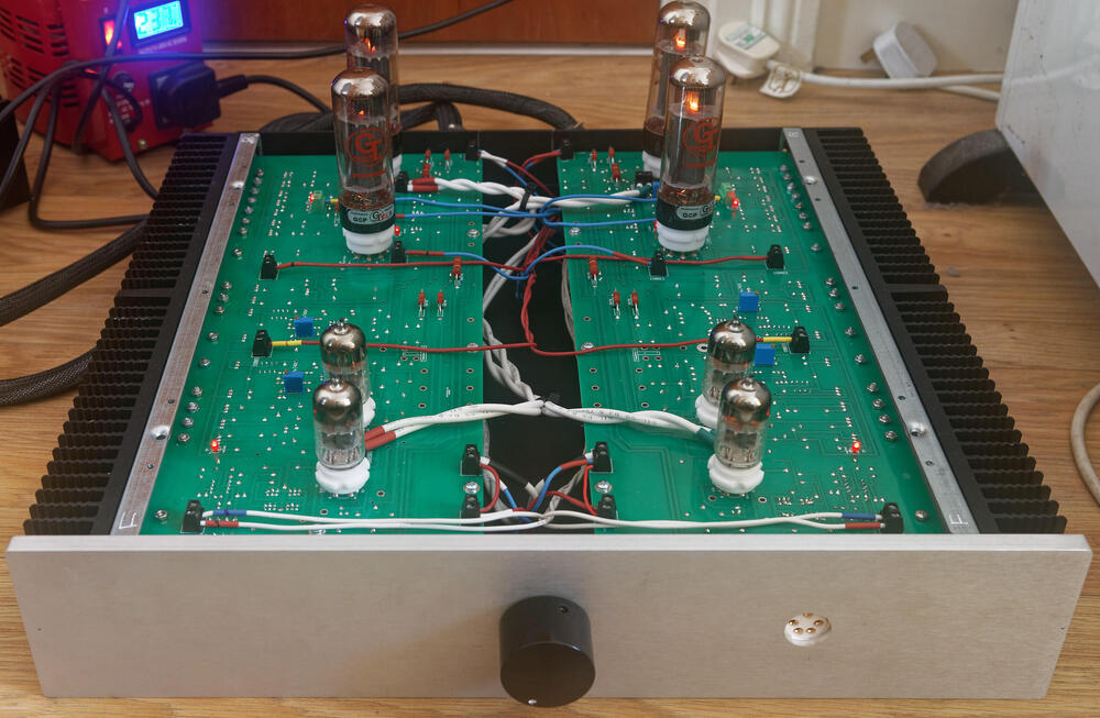
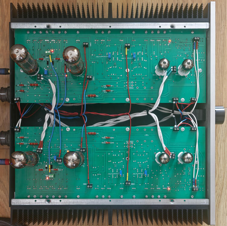

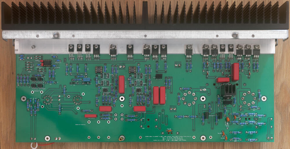
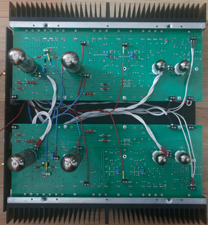
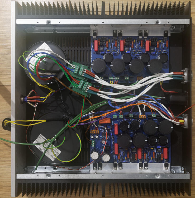
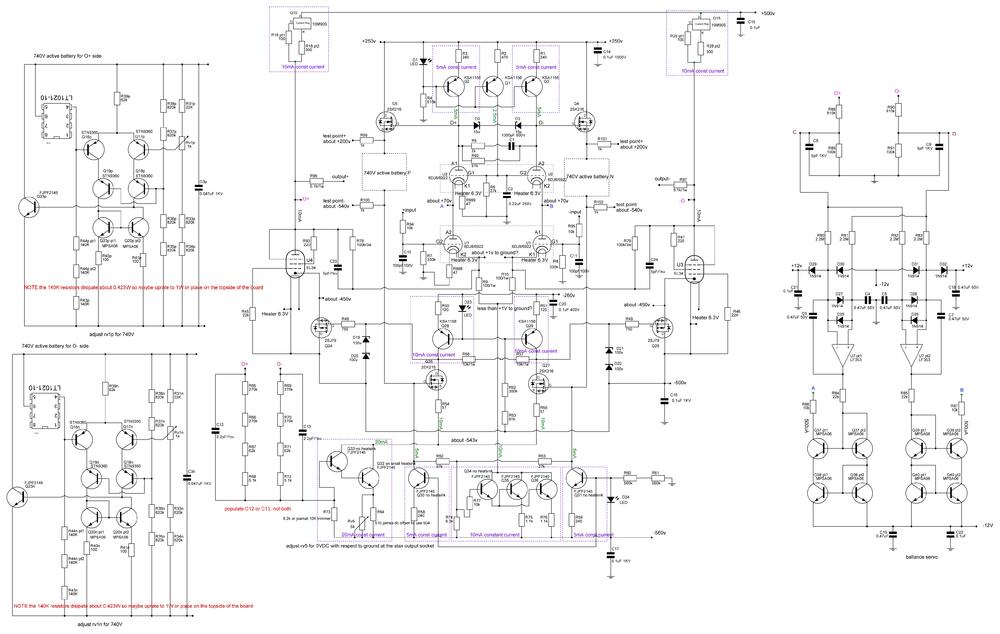
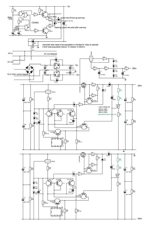
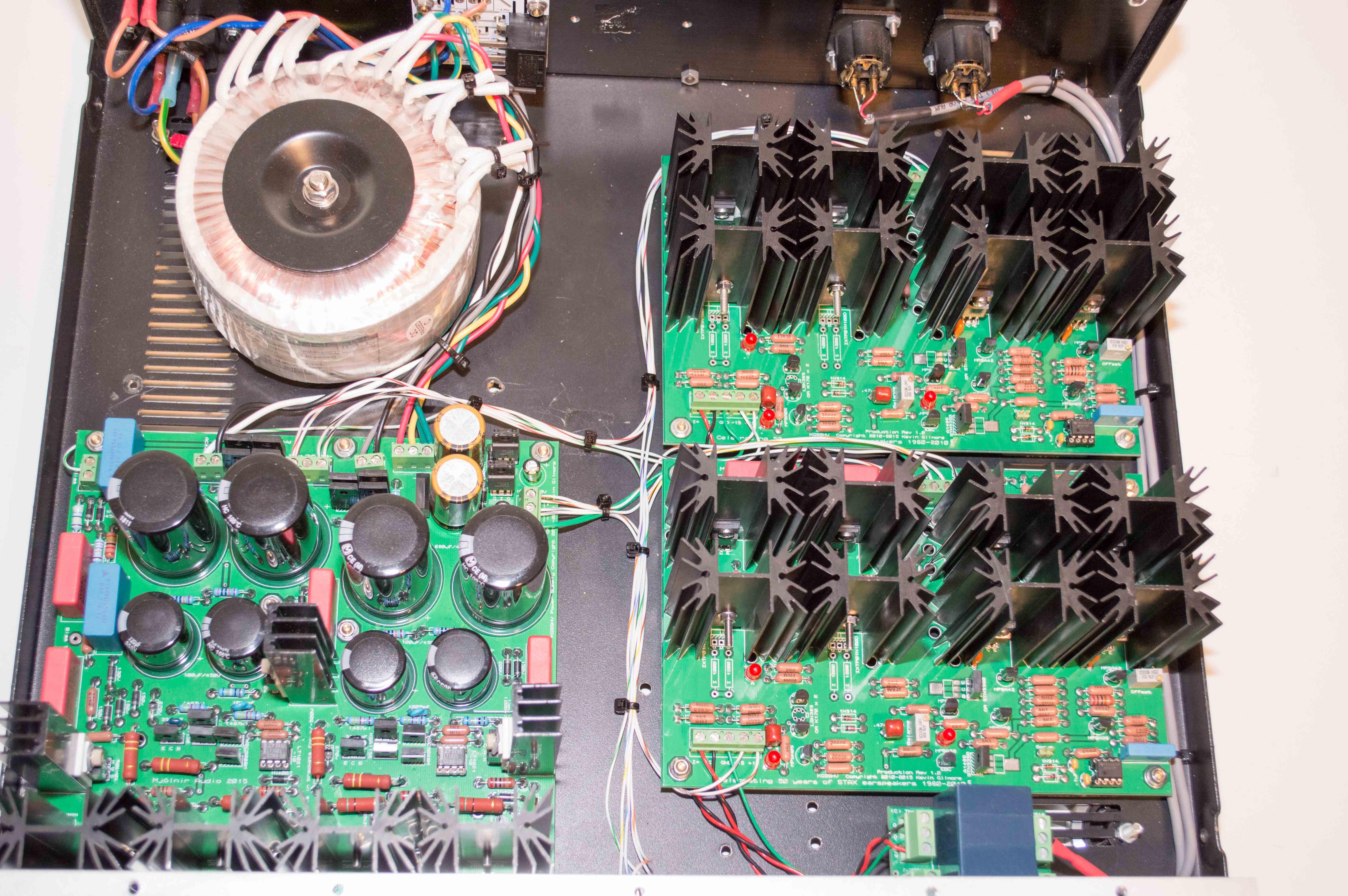
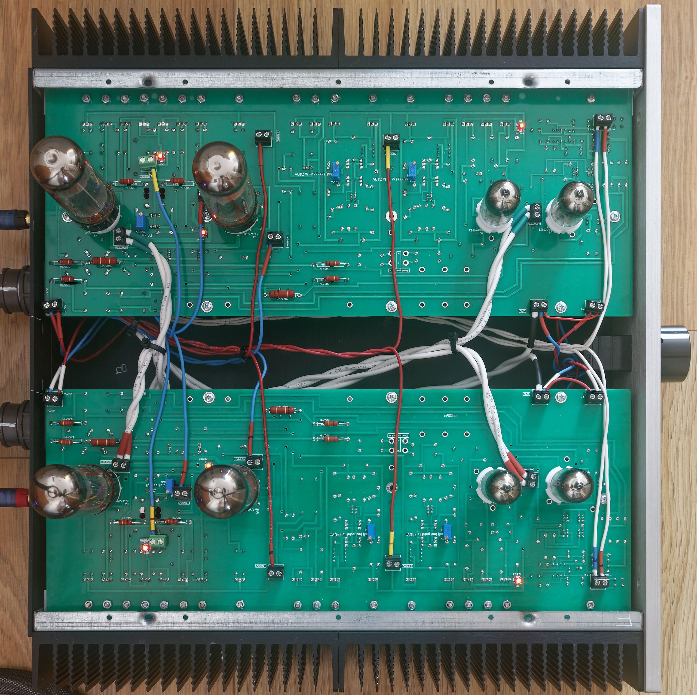
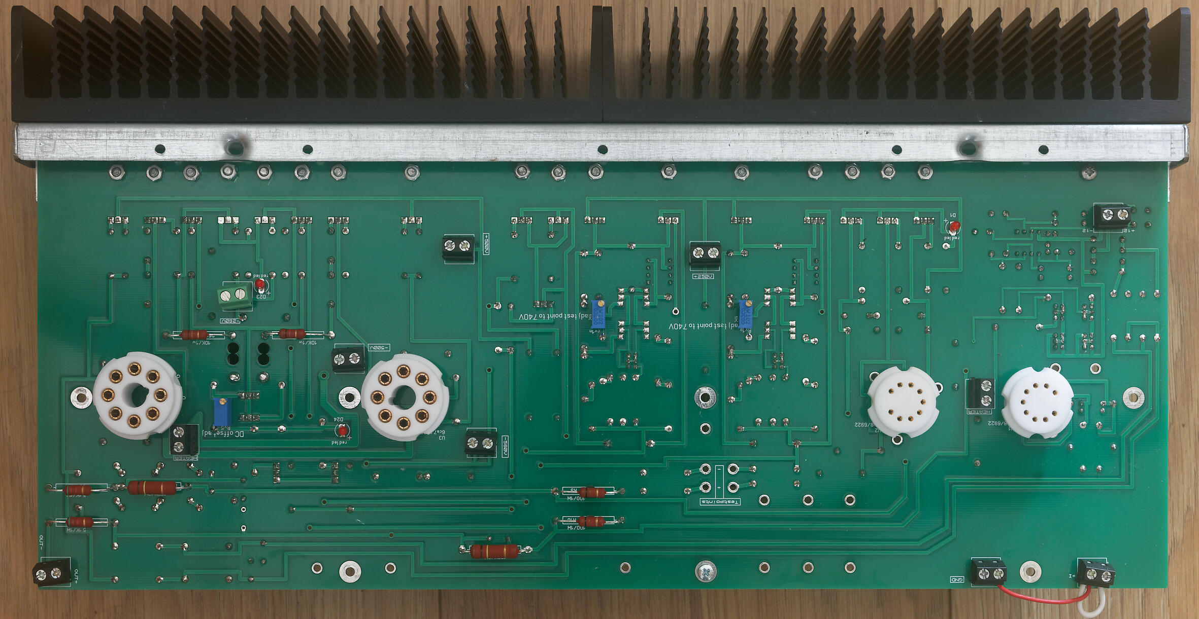
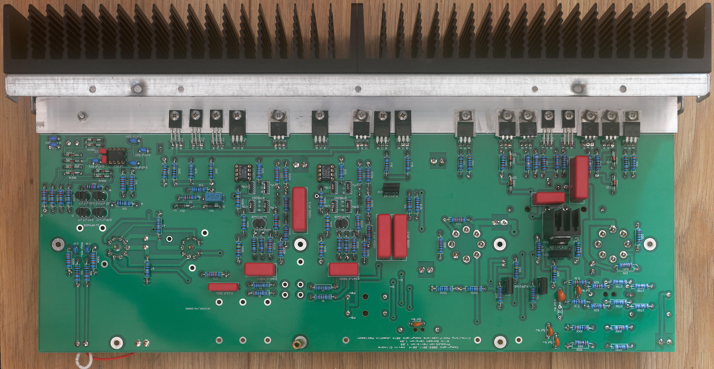
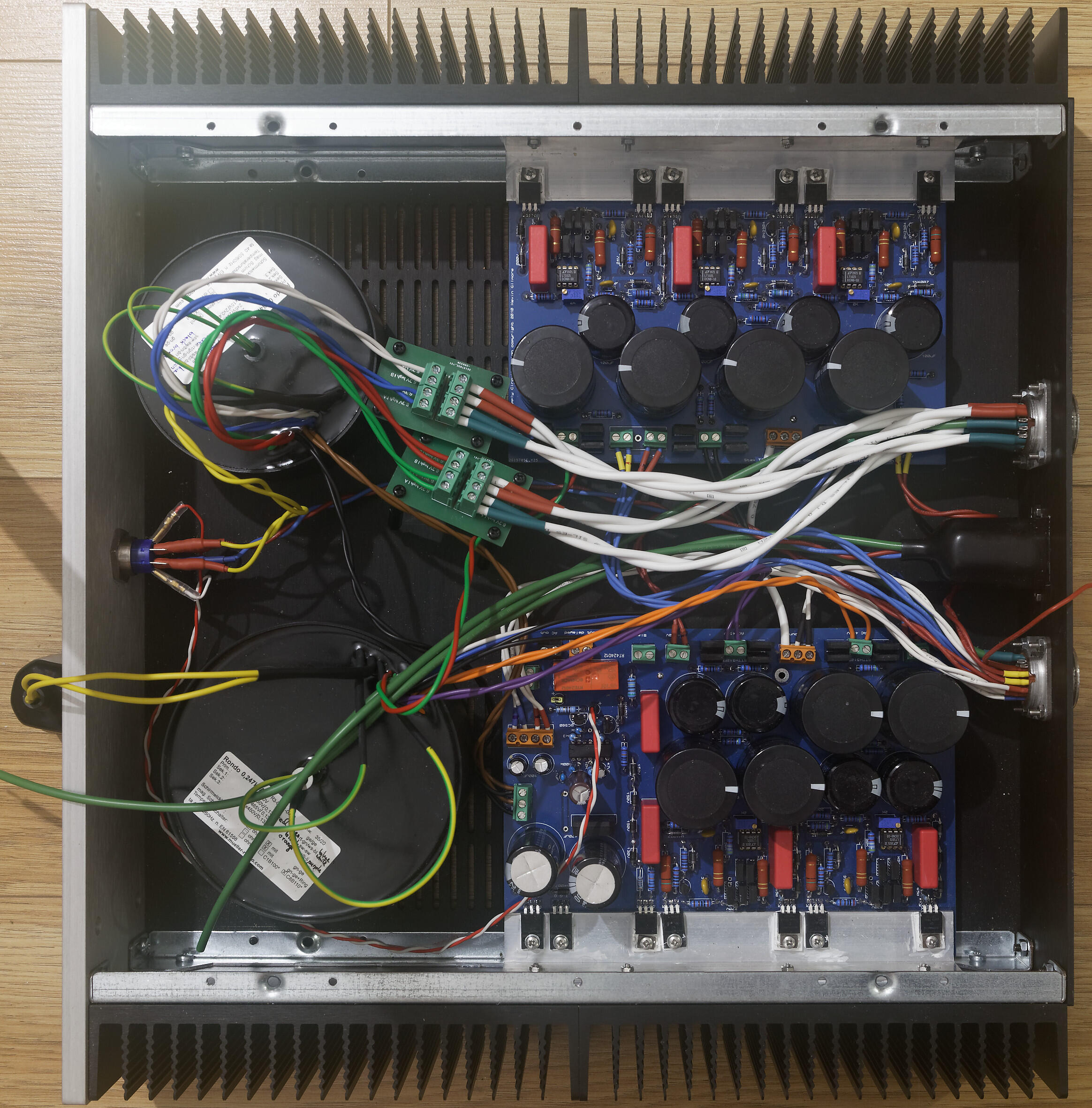
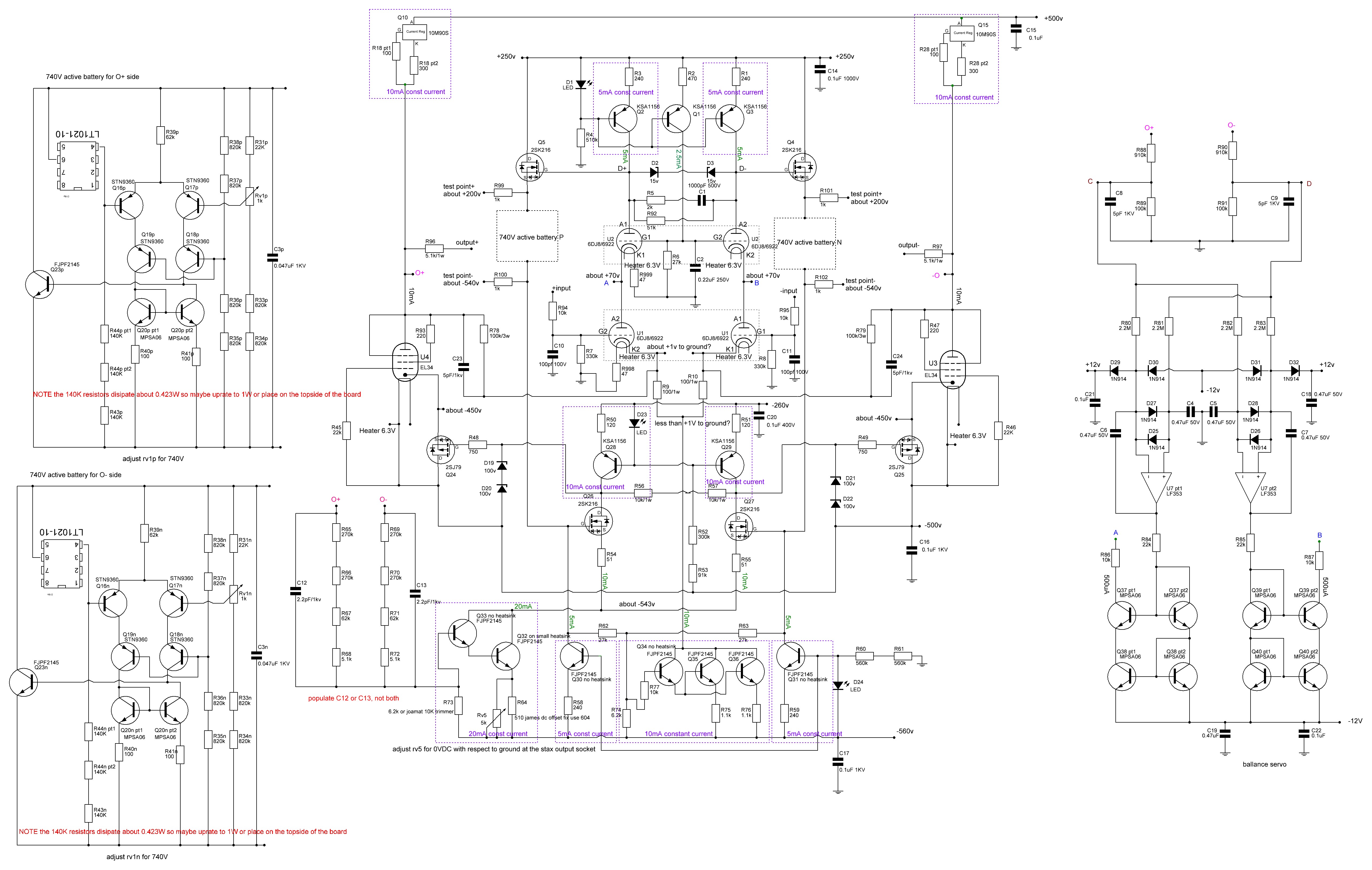
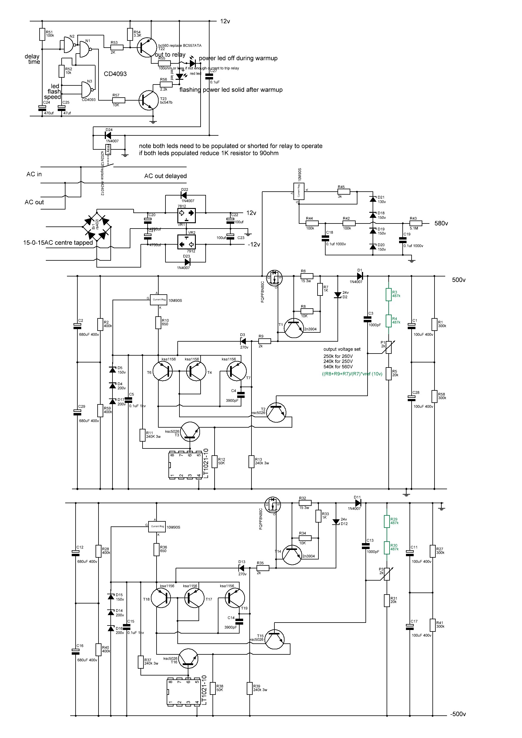
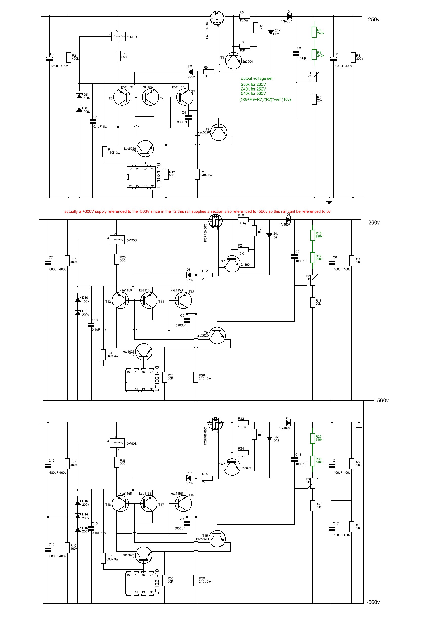
 1 point1 pointIt might be a little premature but I think I now have a working T2 using a modified version of joamat's staxt2nc3fdh7 amp files and kgsshv dc supplies.... Initial startup looks good. Channels started up seperately. Heater transformer running at full voltage. High voltage transformer on a variac. virtual batteries within 100mV of 740V before any adjustment. DC balance between + and - sides of a channel <1V without any adjustment, all 3 leds lit on both channels. once my hands stop shaking I will take a few photos... I have been dreading switch on... in the meantime here's a few build photos of a finished amp channel top and bottom, the amp and psu I modified the delay circuit on one of the psu boards to use a relay instead of the now unavailable solid state relay. I modified the amp boards so that 1. they fit into a 400mm deep chassis, hifi 2000 dissipante chassis. 2. they have screw terminals for all connectors on the top.. (less neat but easier for testing and rebuilding) 3. all resistors of 1W or more go on the top of the pcb with a drill hole under for increased airflow 4. groundpane is between 1.1mm and 1.3mm from any solder point 5. pcb is cut in half so each channel can be built, tested and mounted independently, 6. solder points for pot and input jacks removed and replaced with screw terminals. 7. silkscreen has instructions for adjustment of pots 8. mpsw06 transistors replaced with mpsa06 9. small standalone heatsink for Q34 FJPF2145 in the 20mA current source darlington pair has drill holes in the pcb by the fins for enhanced airflow. 10 all components have schematic numbers included in the silkscreen 11 leds and adjustment pots mounted on top side of pcb like the original T2 12 removed the bias input and 5.1M resistor (since the kgsshv psu already has the resistor in the bias section) I will be happy to release the gerber files of my modification once I am certain the amp is reliable For the build: wima film capacitors, mixture of koa cm1/2 and xicon 273 series 1/2W resistors, for higher wattage vishay pr02 and pr03 All resistors, diodes, zeners raised from the pcb. pcb 2mm with 2oz traces. All 1/2W resistors matched to 0.1% or better at 1khz on a good LCR meter between + and - sections of an amp board AND between left and right channels. all non psu and psu decoupling caps matched to better than 1% at 1KHz on a LCR meter between + and - sections of an amp channel AND between left and right channels. (except for the pF caps which are just too small to measure accurately). all leds and mpsa06 transistors matched on a dca75 curve tracer between + and - sections of an amp board AND between left and right channels. all zener diodes matched to within 1% or better between + and - sections of an amp board AND between left and right channels. separate umbilical cords for AC heater power and DC voltages all internal wiring 1KV silicon all signal wires will be cardas chassis wire volume pot tkd 2500 series left to do install rca signal wiring, volume pot and stax output socket test with signal generator and measure distortion etc collapse from T2 build anxiety drill top of case for valve sockets clean up wiring pray to the god(s) of electronics sort out grounds on psu post moar pictures Here is the schematic for the staxt2nc3fdh7 NOTE this is my reverse engineer based on the pcb and the original T2 schematic and has not been checked by anyone. ( as far as possible component labels reflect the original T2 component labels. In the case of 2 components replacing a single component in the original T2 the components are now labeled Xpt1 and Xp2. In the case of additional components no present in the original T2 they start with the number 9XX. In addition both batteries are shown and the the components labeled with a Xp for the O+ side battery and Xn for the O- side battery. Note the 140K resistors in the virtual batteries dissipate 0.423W each and I found xicon 1/2W 273 series discoloured and drifted by about 1% after about 6 months heavy use when placed on the underside of the pcb. So you may want to think about 1W resistors or place the resistor on the top side of the pcb. psu low voltage, bias, +500V -500V and hv delay reverse engineered from pcb and original schematic. not checked by anyone. psu +250V, -260V and -560V reverse engineered from original schematic and pcb not checked Note psu schematics changed 22/08/2022. Thank you to Rinat for spotting an error on the current path around the 3900pF cap.
 1 pointRoon gives me back a lot of the ritual, but I also think the world has changed and I've changed with it. I can force myself to sit with an iPad as controller and listen to full albums, but I'm not as comfortable doing it as I am listening with less of my attention. My preference for how to listen deliberately is to fullscreen Roon, lock everything into exclusive mode so I don't get system sounds, then occupy my restlessness by reading Roon's equivalents of liner notes like lyrics, reviews, associated artists, etc. If you've not tried Roon, it's not cheap but it's a great experience.1 point1 pointI wasn't sure about posting this but it kinda had to be done. Pic is from HF and the usual nonsense in the peanut gallery there: So this is the Sirrah V3 from high-amp.de...aka yet another slight twist on the Stax SRM-1 Mk2 or derivatives. For me it is just the build here and well... the total shitbox we have here. First off, what's up with all the hotglue? As somebody who has built hundreds of amps at this point... I don't even own a hotglue gun nor would I ever think of using this crap. Some other goodies, top of the transformer sanded for it to fit in the chassis, no insulation on the mains plug which means this would fail even the basic CE tests, nice bit of cloth underneath the pot there to presumably stop it from shorting something on the board and I just love all the transformer leads, not twisted in any way, coming really close to the input wiring. The hand cut heatpads on the output transistors are also nice and I very much doubt that tiny ballast resistor for the bias supply is rated to 600V.... On top of that, look up the design of this thing. Basically a SRM-212 with a full size power supply and some things changed. +/-200V rails, no CCS for the VAS stage and very little power.
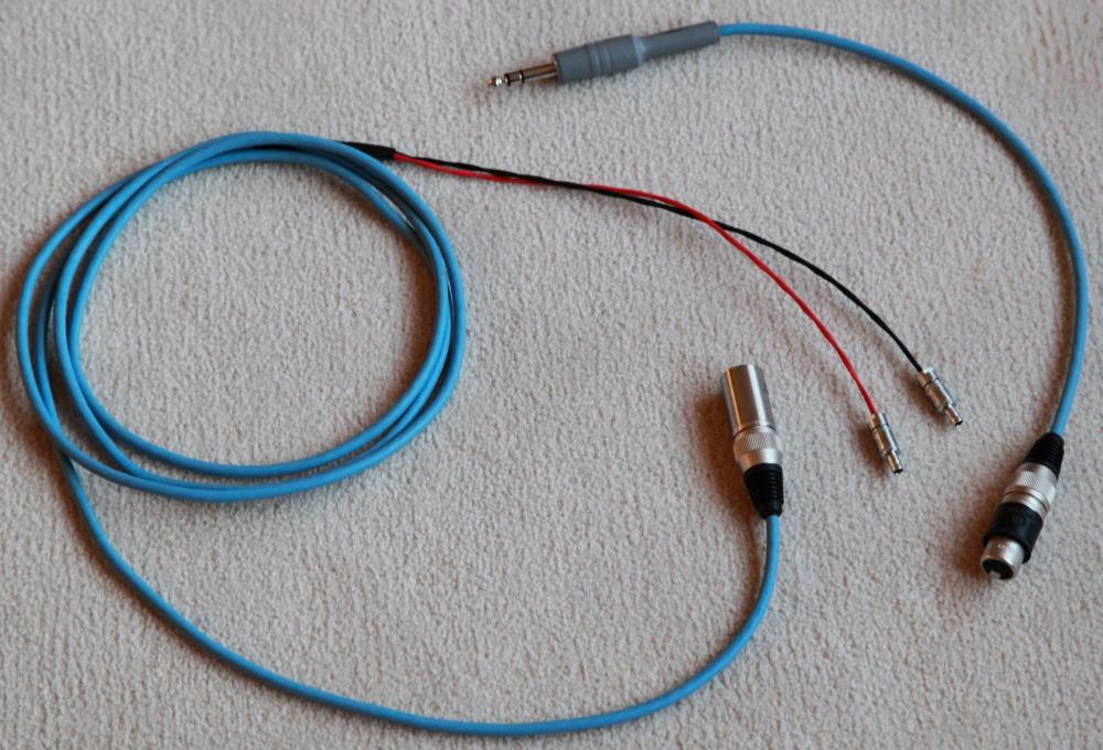
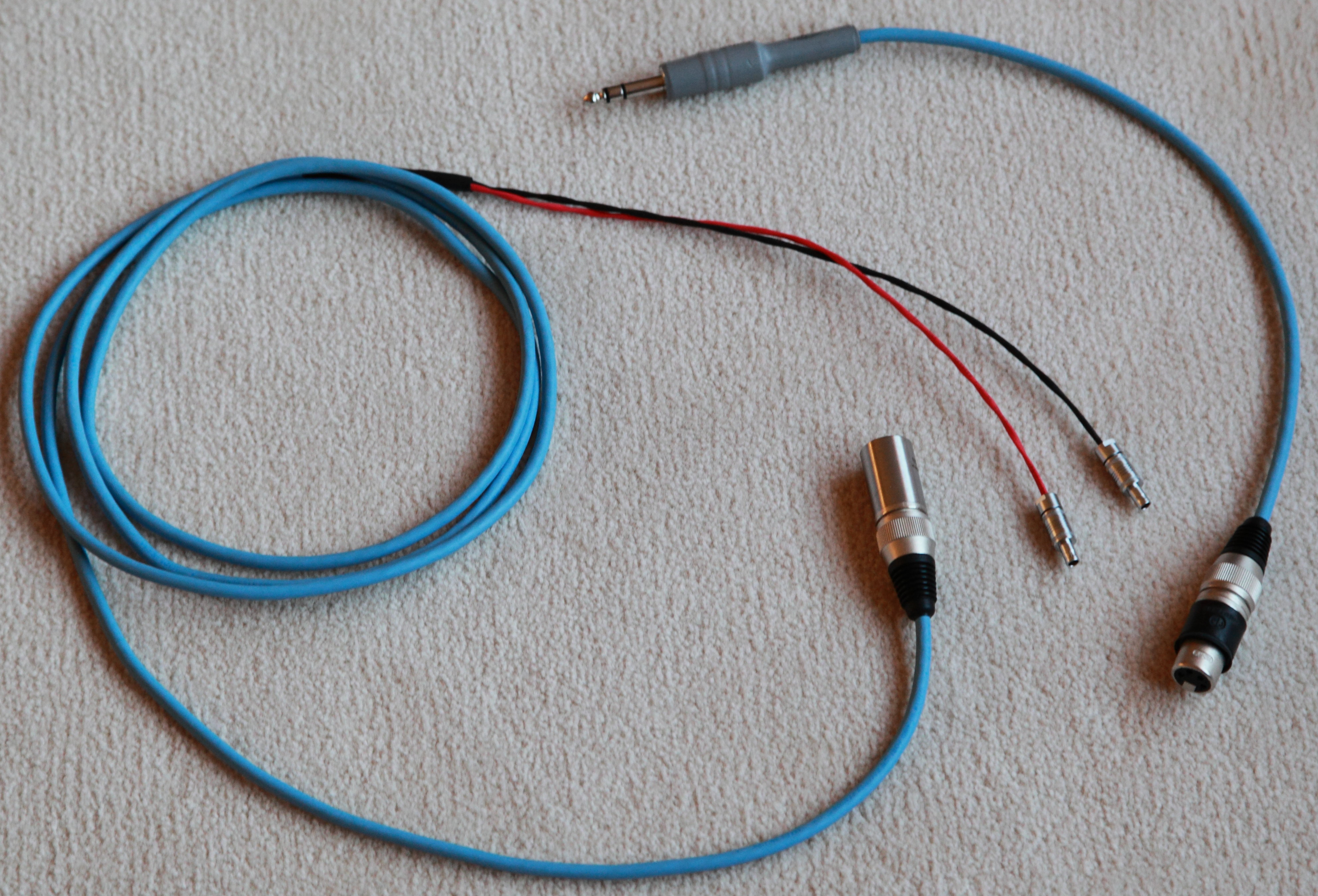
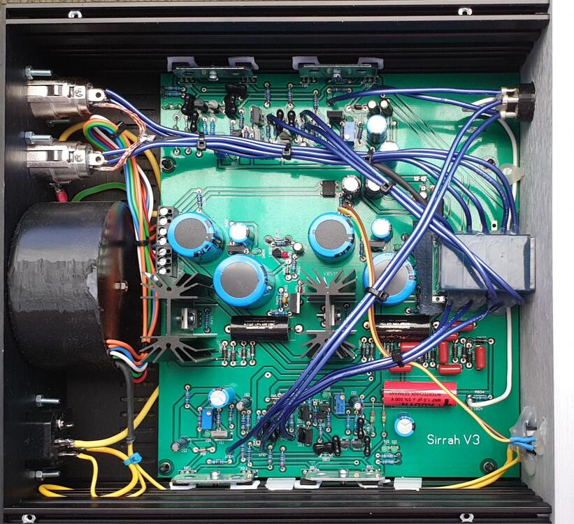 1 point1 pointAnother CFA is alive and well. Sorted out the issue with the bias when using the SS/ZF switch by doing the following (board rev 1.2): - Remove the 4 ZF jumpers near the 600pF - Increase R44/R49 to 50K - Increase R50/R51 to 4.2K - Remove C9/C10 Set at 190mA, plays beautifly in both modes. A must-have as reference in the amp collection. Thanks to KG for developing this amazing circuit!1 point1 pointHarvested an old Cardas Headphone cable to make a balanced cable for the HD800. Neutrik 4-pin XLR connectors. The HD800 connectors are from Parts Connecxion and a royal PITA to work with.
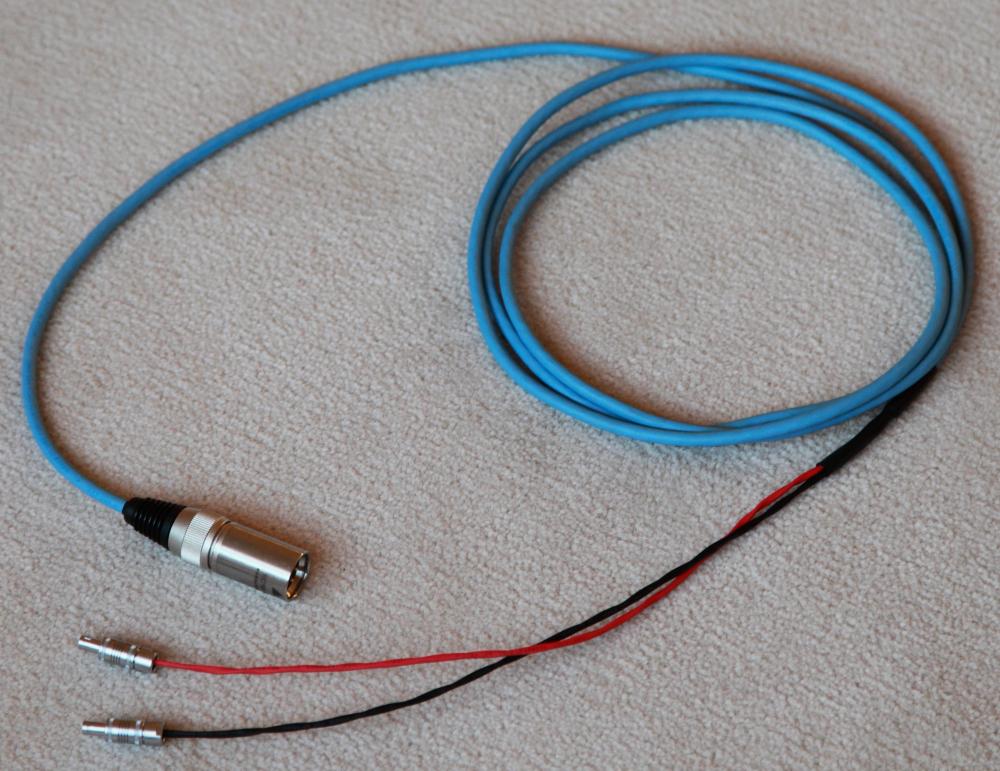
 1 point0 points0 pointsRIP Lou Brock. https://www.google.com/amp/s/amp.cnn.com/cnn/2020/09/06/us/lou-brock-obit-spt-trnd/index.html0 points


Important Information
By using this site, you agree to our Terms of Use.
Account
Navigation
Search
Configure browser push notifications
Chrome (Android)
- Tap the lock icon next to the address bar.
- Tap Permissions → Notifications.
- Adjust your preference.
Chrome (Desktop)
- Click the padlock icon in the address bar.
- Select Site settings.
- Find Notifications and adjust your preference.
Safari (iOS 16.4+)
- Ensure the site is installed via Add to Home Screen.
- Open Settings App → Notifications.
- Find your app name and adjust your preference.
Safari (macOS)
- Go to Safari → Preferences.
- Click the Websites tab.
- Select Notifications in the sidebar.
- Find this website and adjust your preference.
Edge (Android)
- Tap the lock icon next to the address bar.
- Tap Permissions.
- Find Notifications and adjust your preference.
Edge (Desktop)
- Click the padlock icon in the address bar.
- Click Permissions for this site.
- Find Notifications and adjust your preference.
Firefox (Android)
- Go to Settings → Site permissions.
- Tap Notifications.
- Find this site in the list and adjust your preference.
Firefox (Desktop)
- Open Firefox Settings.
- Search for Notifications.
- Find this site in the list and adjust your preference.