

Leaderboard
-
VPI
High Rollers14Points9103Posts -
swt61
High Rollers6Points22243Posts -
MASantos
High Rollers5Points594Posts -
CarlSeibert
High Rollers4Points2512Posts


Popular Content
Showing content with the highest reputation on 10/19/16 in Posts
-
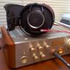
5 pointsWell I haven't tested the preamp alone. I replaced a Rega Brio integrated with the salas phono stage, BA3 pre and F4 power amps. Overall the improvement was very impressive. Much better control of the low end and also a wider soundstage with more "air". Overall the sound is quite "musical, but not the most detailed.( the ba3 is not know for being the most detailed amplifier out there.). When I connect a digital source there is also some improvement so I can say the the phono stage is responsible for some of that nice sound! Here are the latest pics: Dirty psu section with line filter. Dual mono PSU umbilical. The black knob works as on/off switch, input selection and volume control. When turned on there are 2 numeric led displays on behind the black acrylic for volume display. 64 steps Control board for the attenuator/source selector. Remote control receiver on the front side, Cat5 wiring for signal. Salas SSLV regulators, BA3 front end at 30V and relaixed passive attenuator. using vishay self resistors. The control board for the attenuator is in the front panel and the power relay/5V control voltage section pcb is in the psu case. 8 wire umbilical carries control wiring and dual mono DC for the regulators. "gain" is the output from the BA3 preamp, "0db" does not have any active circuitry in the signal, so it is a passive preamp output, "loop" simply outputs the selected source, so it is just a source selector. The two AC female connectors are controlled by the preamp on/off relay switch (10A/250V), so when I turn the preamp on I can turn 2 other devices at the same time. ATM using one of them for the phono stage, might feed a DAC in the future with the other one. Preamp PSU. System in my DIY oak rack (solid oak kitchen countertop cut to size) A small video of the system playing, you can see the F4 power amplifier behind the left speaker. It will eventually be placed in the large lower opening in the rack, but I need to build ventilator to extract all the heat (200W) from those heatsinks. Some sort of undershelf with 140mm computer fans is on the way. https://youtu.be/OpMUCAIiMUY5 points
-
3 pointsThanks, everyone. Michelle and I had a blast in Vancouver last night (highlight being the Shameful Tiki Room), and enjoyed wonderful scenery driving north to Whistler today. Beers in Portland tomorrow then on towards home. Sent from my VS990 using Tapatalk3 points
-
2 points
-
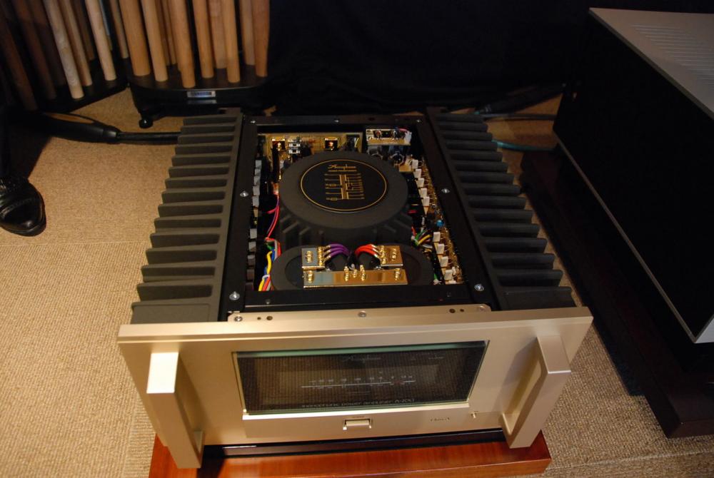
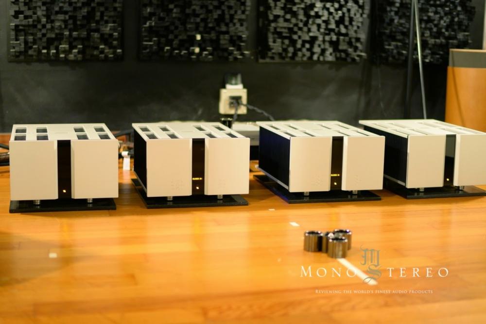
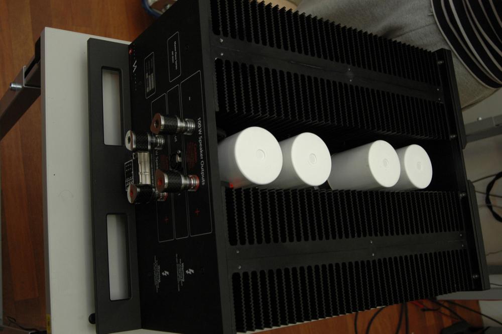
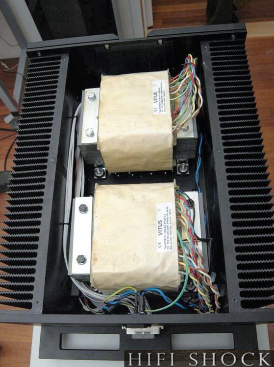
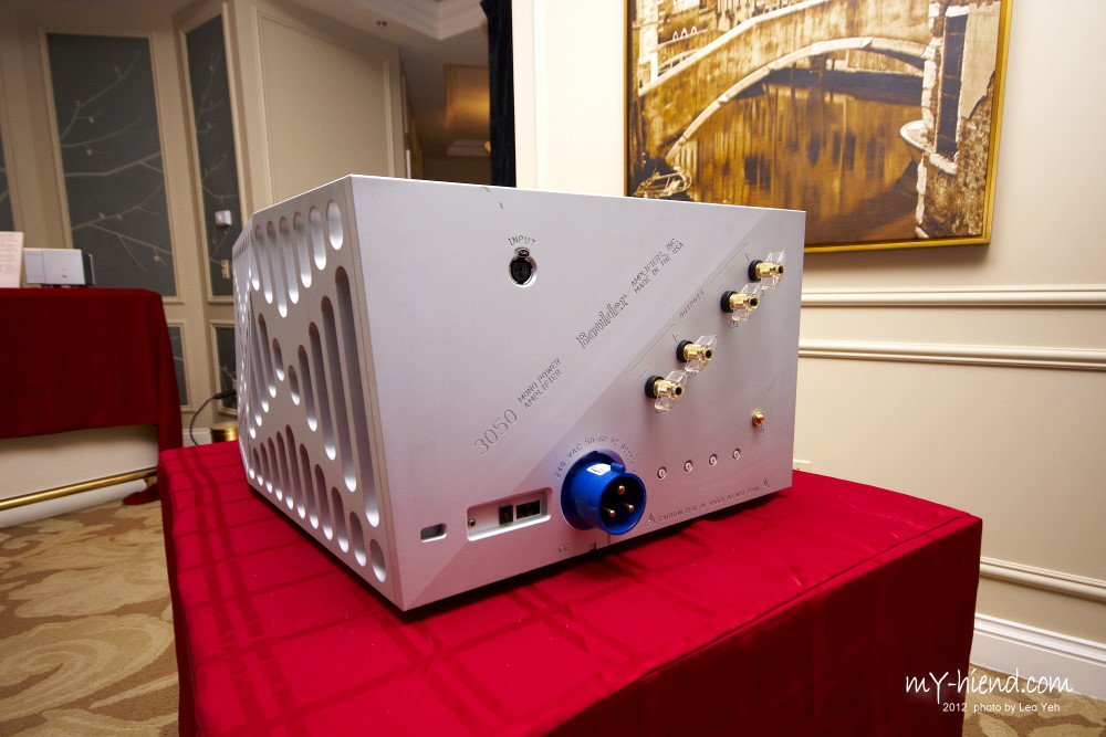
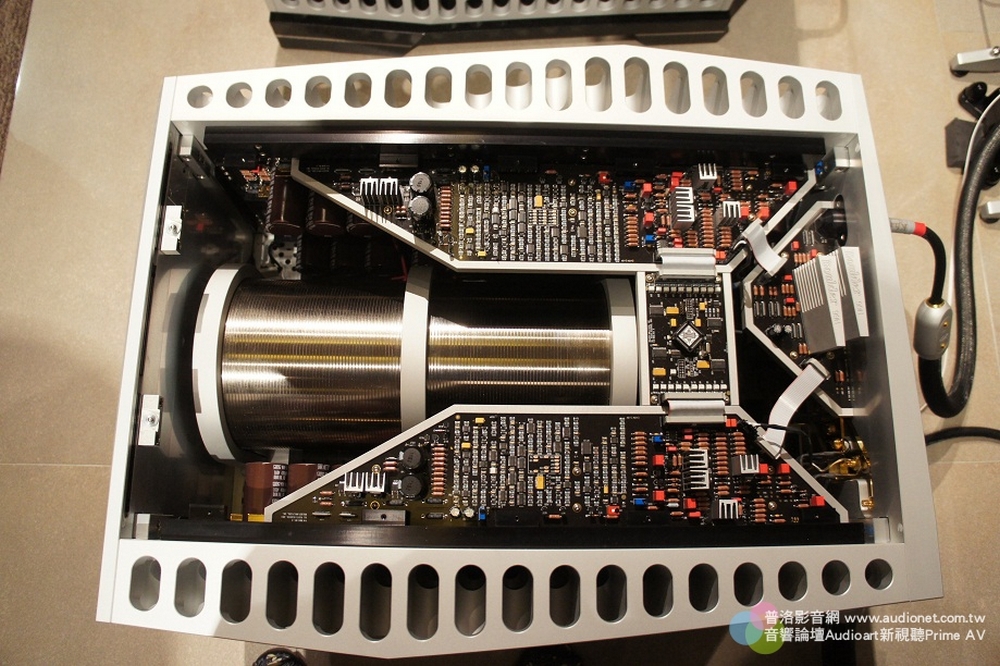
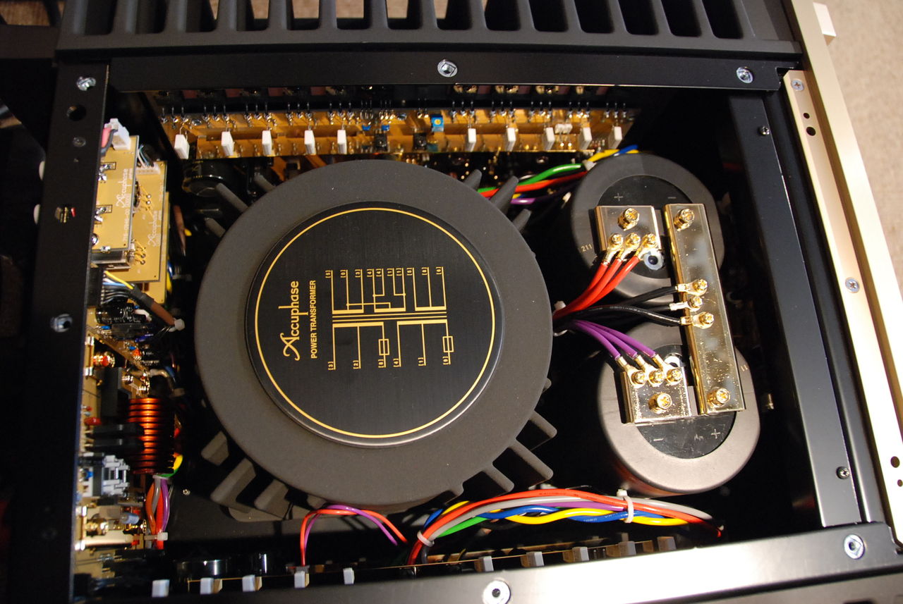
1 pointThere is a speaker porn thread, so why not an amplifier porn thread? Gryphon Colosseum VITUS MP-M201 Accuphase A-200

 1 point
 -
1 pointThe Naim Statement. About the same price as the boulder above, but at least you get a preamp (the middle slice).1 point
-
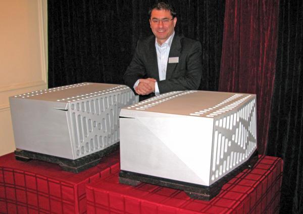
1 pointThe baddest boy on the block... I think they should rename the company to Boner Amps, instead of Boulder Amps. And just a mere $205,000 per pair.
 1 point
 -
I've been using OP07 because its cheap and +-22v also it says in datasheet (2) All voltage values, unless otherwise noted, are with respect to the midpoint between VCC+ and VCC−. so the way I read it ........ can use on GRLV up to 40v output... and have been1 point
-
1 point
-
1 pointHave a Peter filled day...Wait, have a day filled with Peter... (I must be thinking of my Birthday) Just have a fabulous day Peter!1 point
-
1 pointStopped from my chores to watch salmon try to fly https://vimeo.com/1878938121 point
-
1 point
-
1 point
-
1 point
-
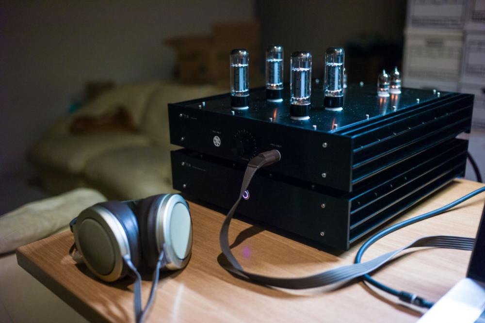
1 point1 point1 point1 pointHappy birthday, eh! Have a great one in the Great White North. Cheers!1 point1 point1 point1 point1 point1 point1 point1 point1 point1 point1 point1 point1 point1 point1 point1 point1 point1 point1 point1 pointHappy Birthday!!! Not sure about filling, but the feeling is that you have a great day1 point1 pointToday, my DIY T2 has successfully come to life! After a year on and off working on this amp on my kitchen table, I was able to power up today and get music playing. All 4 batteries are sitting around 743V. The +/- voltages for each channel are surprisingly well balanced, and both L and R sit about +10V offset at power-on and gradually get down to about 2-4V offset at steady state. I measured the heatsink temperature -- looks like it's steady at 124F/51C after about 3 hours continuous burn-in. A shoutout to GeorgeP for enabling this build--one of my good buddies helped me reached out to you about a year ago for the case/amp board/torroid set. Thanks KG, Spritzer, and everyone else who posted all the useful information on every aspect of the amp on this thread. I learned a lot through the process of building this amp! One interesting thing I found while testing the PSU was that when I had both HV toroids hooked up and powered, the combined inrush blew through my 3.15A slow blow fuse (at 120VAC from the wall). I take it that the inrush of the 2x HV toroids (at least on my toroids) are pulling closer, but not quite, to 4A, since I was able to power up one HV toroid with a 2A fuse that I had left over. I have a 5A slow blow in there now, and so far no issues! -Kuen
 1 point1 point1 pointI think it would be cool to actually remove the amplifier circuit from the board and make it modular - plug-in boards for the amplifier section and maybe even the PSU. Would there be interest in something like this down the road?1 point


Important Information
By using this site, you agree to our Terms of Use.